Welcome to Our Community

Some features disabled for guests. Register Today.

The Beeline CNC

Discussion in 'CNC Mills/Routers' started by blterry1, Feb 28, 2018.
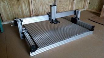
  1. blterry1

    blterry1 New
    Builder

    Joined:
    Sep 6, 2015
    Messages:
    9
    Likes Received:
    35
    blterry1 published a new build:

    Read more about this build...
     
  2. devloop

    devloop Well-Known
    Builder

    Joined:
    Dec 9, 2017
    Messages:
    61
    Likes Received:
    86
    That cutting bed is the way to go!
     
    blterry1 likes this.
  3. Scotty Orr

    Scotty Orr Journeyman
    Builder

    Joined:
    May 21, 2015
    Messages:
    315
    Likes Received:
    177
    Nice build! I like the traveling C-beams. Can't wait to see it in action. Good luck in the contest!
     
    blterry1 likes this.
  4. blterry1

    blterry1 New
    Builder

    Joined:
    Sep 6, 2015
    Messages:
    9
    Likes Received:
    35
    I think it'll come in handy for some t-slot style clamps. And it was way way cheaper this way than the pre-made fixture plates I've seen online.
     
  5. blterry1

    blterry1 New
    Builder

    Joined:
    Sep 6, 2015
    Messages:
    9
    Likes Received:
    35
    Thanks! I had lots of doubts about posting it because I hadn't shown it to anyone else, so it means a lot to be hearing good feedback from the OB community.
     
  6. pek

    pek Journeyman
    Builder

    Joined:
    Apr 17, 2017
    Messages:
    196
    Likes Received:
    130
    Very nice build, looks simple and efficient. I love when there is such a well detailed manual! Good luck for the contest :)

    Do you know approximately the cutting surface?
     
    blterry1 likes this.
  7. blterry1

    blterry1 New
    Builder

    Joined:
    Sep 6, 2015
    Messages:
    9
    Likes Received:
    35
    Thanks! If I remember right, it should be about 850mmx850mm in X and Y. Z has a 250mm travel, but that's going to depend on router size and placement and the thickness of the spoil board and material.

    I'll update the build with the specs once I know for sure.
     
  8. captainporksword

    Builder

    Joined:
    May 27, 2017
    Messages:
    1
    Likes Received:
    1
    best instructions on building ive seen on this site yet after looking at builds for 1 day
     
    blterry1 likes this.
  9. SecretSpy711

    SecretSpy711 Well-Known
    Builder

    Joined:
    Jan 29, 2015
    Messages:
    31
    Likes Received:
    27
    I'm interested in doing a "subplate" base made from extrusions like you have done. Looks like you have ten 1x4 extrusions? I'm concerned about the flatness of the pieces next to each other. Have you measured the flatness?
     
  10. blterry1

    blterry1 New
    Builder

    Joined:
    Sep 6, 2015
    Messages:
    9
    Likes Received:
    35
    I ran a dial indicator down the length and it's not like MIC-6 tooling plate, but when you add a spoilboard and face it, it'll be as flat as you're willing to spend the time to calibrate. I believe it was within .002" or better with bare metal when I measured it, but my machine is also on top of a cheap plywood workbench, so I'm assuming that introduced some inconsistency.

     
  11. mikework

    mikework New
    Builder

    Joined:
    Jul 19, 2017
    Messages:
    15
    Likes Received:
    9
    Hello.

    I am rebuilding my gantry plates and was wondering what was the purpose of the 4 shafts in the assembly? Do they help with rigidity? Its the first time i have seen something like that.

    This is my build.
    My 1st C-Beam CNC
     
  12. blterry1

    blterry1 New
    Builder

    Joined:
    Sep 6, 2015
    Messages:
    9
    Likes Received:
    35
    Sorry, I'm not really sure what 4 shafts you're referring to. Are you talking about the 20x80s on the front and back?

    Your machine looks good, though. If I had a more reliable and permanent surface to build mine on, I probably would have skipped those 2, but I wasn't exactly sure where my machine would live, so I wanted it to be semi portable if necessary.

     
  13. mikework

    mikework New
    Builder

    Joined:
    Jul 19, 2017
    Messages:
    15
    Likes Received:
    9
    Your build pictures shows 4 shafts (representing M5 bolts) support the wheels, and 4 additional shafts.

    I am curious what the effect of these are? Where they put in place to deal with something specific or just add rigidity?

    I have not seen this in other gantry assemblies.

    The reason I ask, other than rebuilding my gantry plates, is that I am upgrading to a 2.2kw WC spindle so am doing a lot of thinking about gantry options.

    Thus am curious as to the effect of these addition supports.

    Thank you!

    upload_2018-9-13_16-42-38.png
     
  14. blterry1

    blterry1 New
    Builder

    Joined:
    Sep 6, 2015
    Messages:
    9
    Likes Received:
    35
    Oh, ok. I understand now. They attach the gantry assemblies to the vertical C-Beams with tee nuts. I don't know what they're like without them, but they are extremely rigid assemblies with the spacers installed.
     

Share This Page

  1. This site uses cookies to help personalise content, tailor your experience and to keep you logged in if you register.
    By continuing to use this site, you are consenting to our use of cookies.
    Dismiss Notice