Step 1
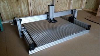
Fixture Plate
Materials Needed:
- 10x - 20x80x1000mm Extrusion
- 3x - 20x60x1000mm Extrusion
- 100x - Black Angle Corner Connector
- 200x - M5x8mm Low Profile Screw
- 208x - Tee Nut
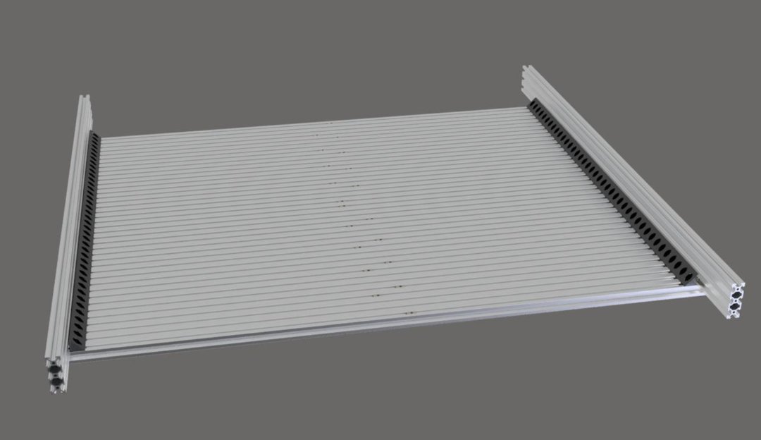
Lay 2 of your 20x80 extrusions down onto a flat surface, about half a meter apart. One extrusion will only be used as a support at this time.
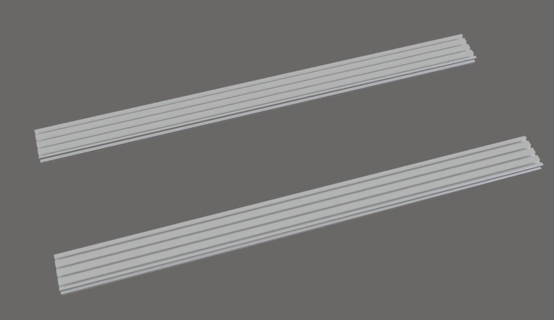
Insert 4 tee nuts into each end of one of your 20x80 extrusions. Also, insert an extra tee nut into the first and last slots. These will go near the middle of the extrusion and will be used to hold the middle brace in place later.
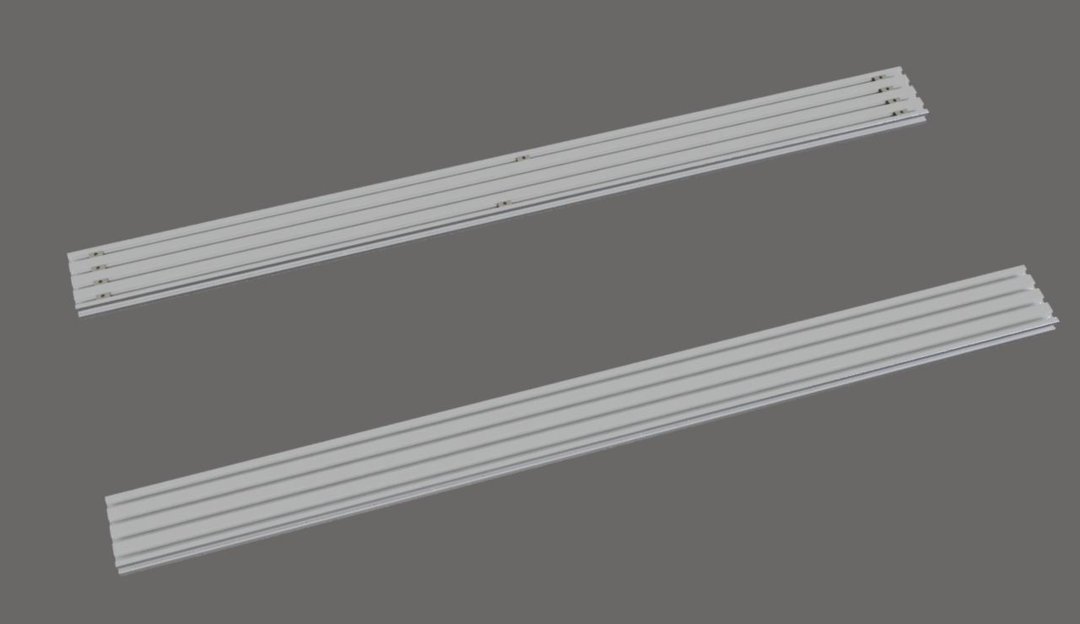
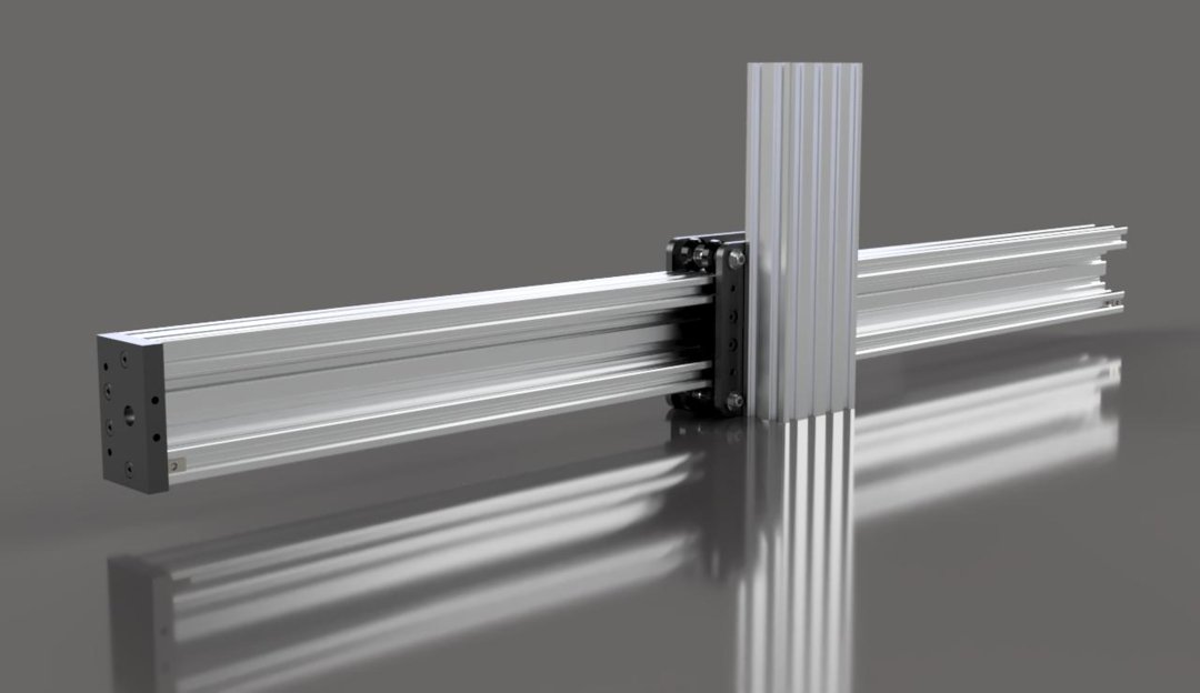
Place 1 20x60 extrusion vertically on top, perpendicular to them.
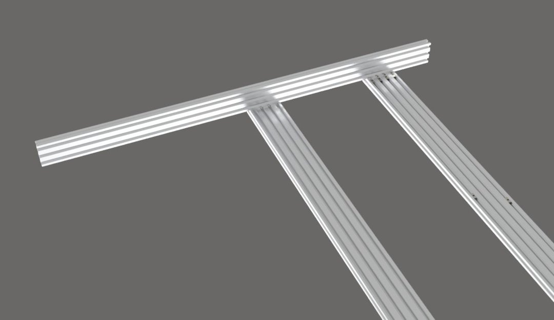
Measure and mark 100mm from one end of the 20x60 extrusion. This is where the 20x80 extrusion should be placed.
Insert 4 Tee nuts into the bottom-inside slot of the 20x60 extrusion.
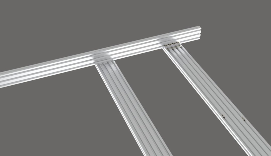
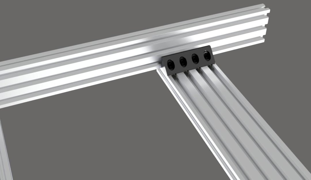
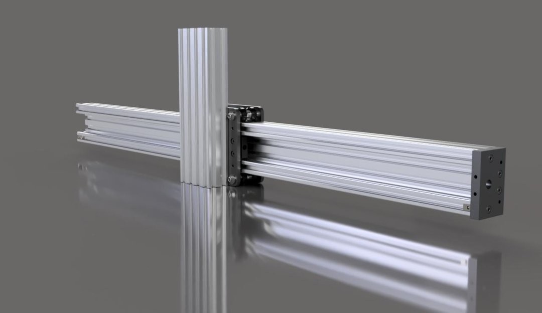
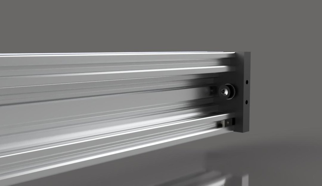
Using a square, align the 20x80 extrusion on the mark you made previously. The end of the extrusion should be flush with the outside wall off the 20x60 extrusion.
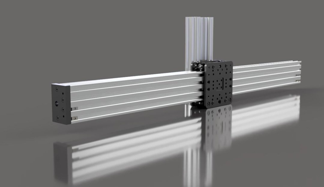
Using 4 corner connectors and 8 M5x8mm screws, attach the two extrusions together. Be careful to keep them square to each other. This part is critical because it will determine how square the rest of the machine is.The corner connectors have some play in them, so I found that it is a good idea to push them toward the outside when tightening them down to ensure there will be plenty of room for all of them.
Place the other 20x60 extrusion onto the other end of the 20x80 extrusion, insert 4 tee nuts, and repeat the same process from the other side. Again, be sure to make a mark 100mm from the end, and keep the extrusions square to each other.
Insert 36 more tee nuts into the same slot on each of the 20x60 extrusions.

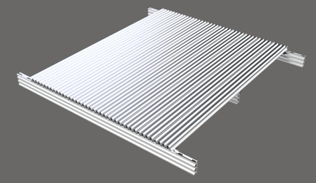
Place the other 9 20x80 extrusions in a row next to the first one.
Insert a tee nut into all 4 slots on both ends of all 9 20x80 extrusions. Remember to add an extra to the first and last slots of each of these extrusions to hold the middle brace later.
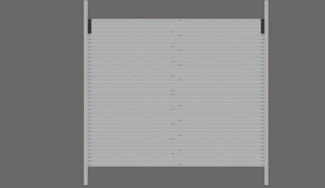
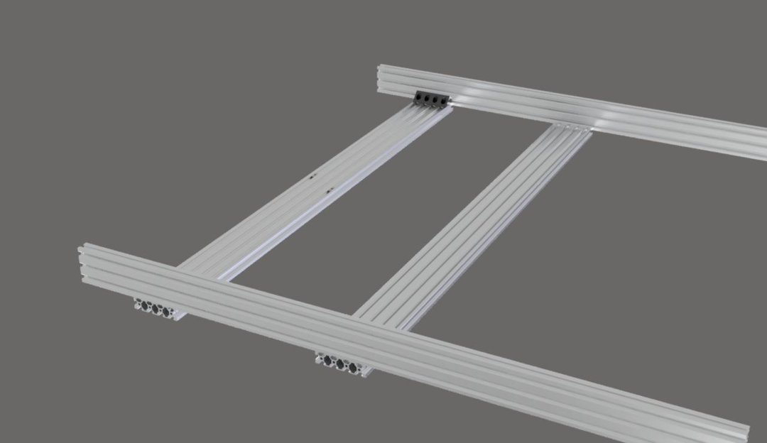
Use a corner connector and 2 M5x8mm screws to attach all of the 20x80 extrusions to both 20x60 extrusions. Do not tighten them down fully yet. Only tighten them enough to keep everything together.
Stand the assembly on one end with the 20x60 extrusions going vertically and the tightened 20x80 extrusion on bottom.
The 20x80 extrusions should now slide into place. If they were fastened too tightly, they may not slide. If this happens, loosen the corner connectors just enough to allow movement.
With all of the 20x80 extrusions aligned to each other, you can start tightening the corner connectors. Start from the bottom and work your way up from there. Make sure that the end is flush with the first 20x80 extrusion. I also found that it was helpful to clamp the 20x80 to the 20x60 with one hand while tightening with the other. Make sure to keep each extrusion flat to the previous one as you go.

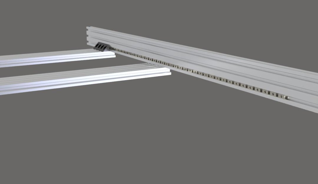
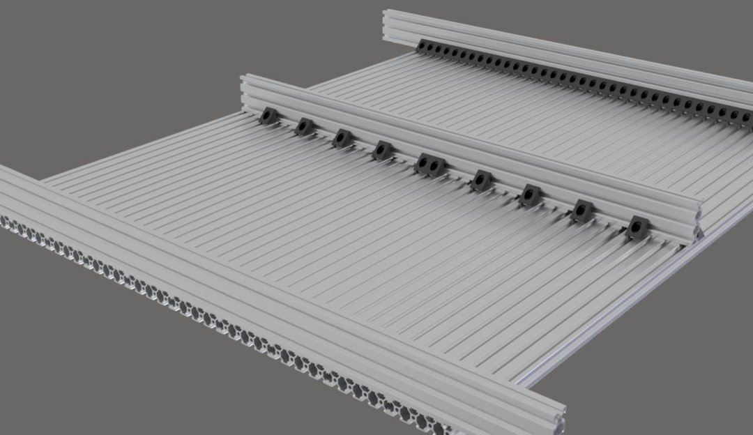
Lay your assembly back down with the middle tee nuts facing up.
You will need to cut your last remaining 20x60 extrusion from 1000mm in length down to 800mm. I used the width of all the assembled 20x80 extrusions to mark the correct length. This in an important step. If you do not cut this extrusion down, it will interfere with the Y axis movement.
Insert 10 tee nuts into the bottom slot of each side of your 20x60x800mm extrusion.
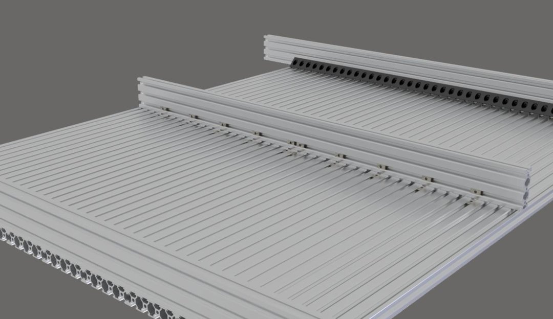
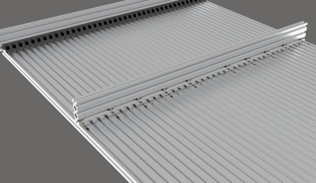
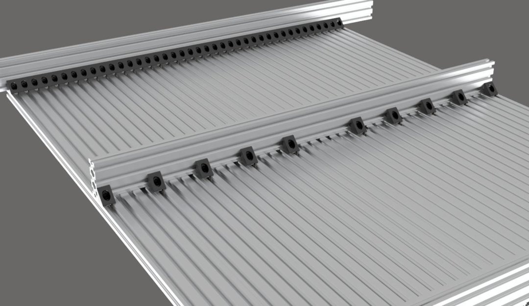
Place the extrusion perpendicular to the 20x80 extrusions. Ideally, you want this extrusion to be 500mm from the end of the 20x80 extrusions, but it is not extremely important to be precise with the placement. This extrusion is only a brace to prevent sag in the middle of your fixture plate, so slight misalignment shouldn’t affect the movement of your machine.
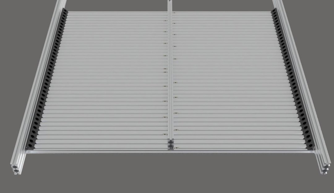
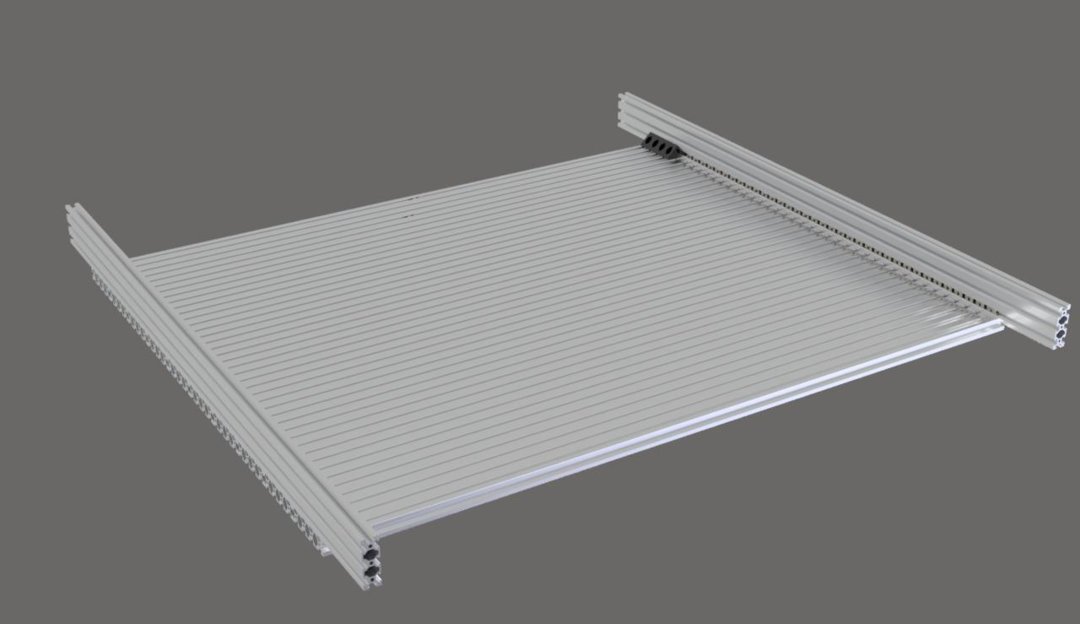
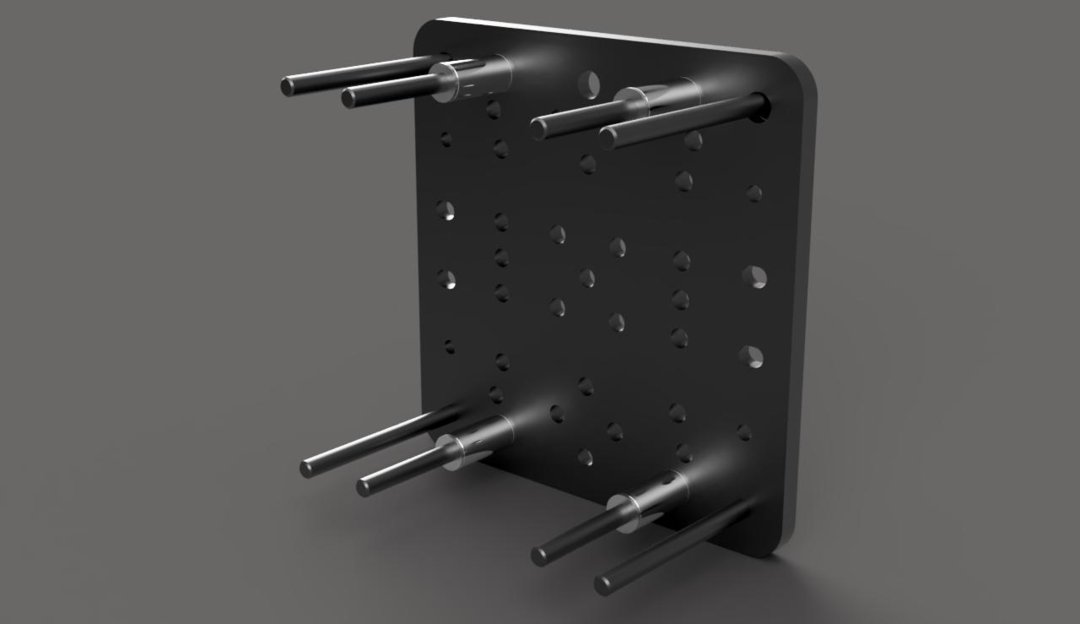
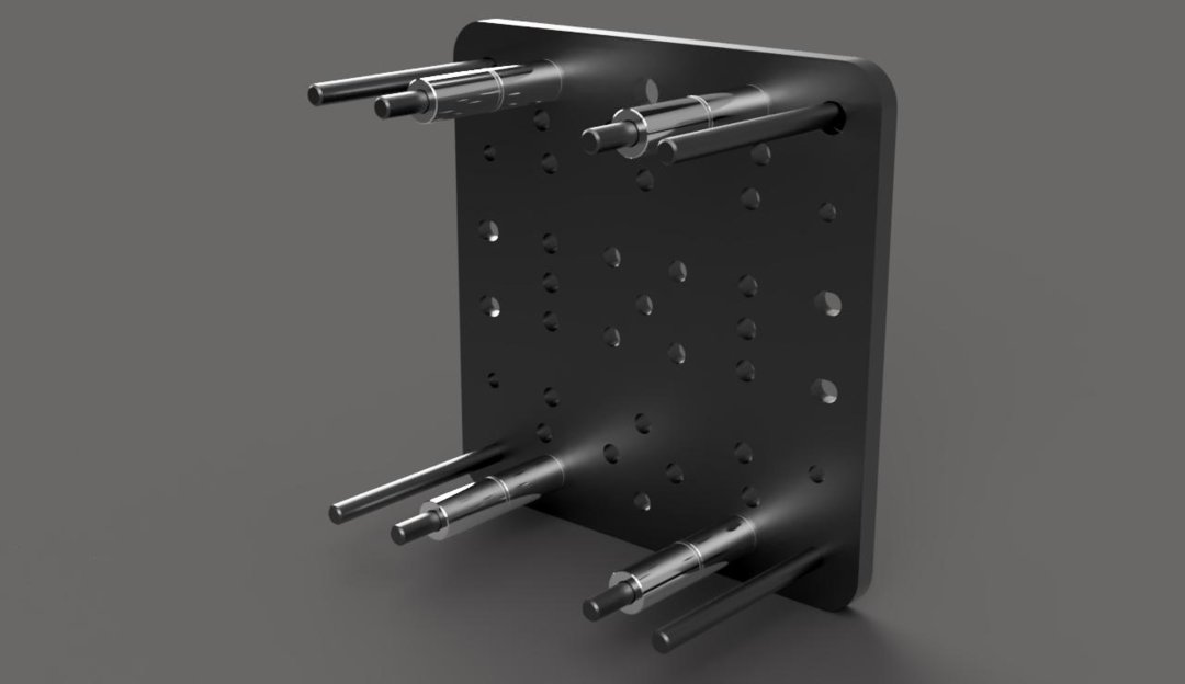
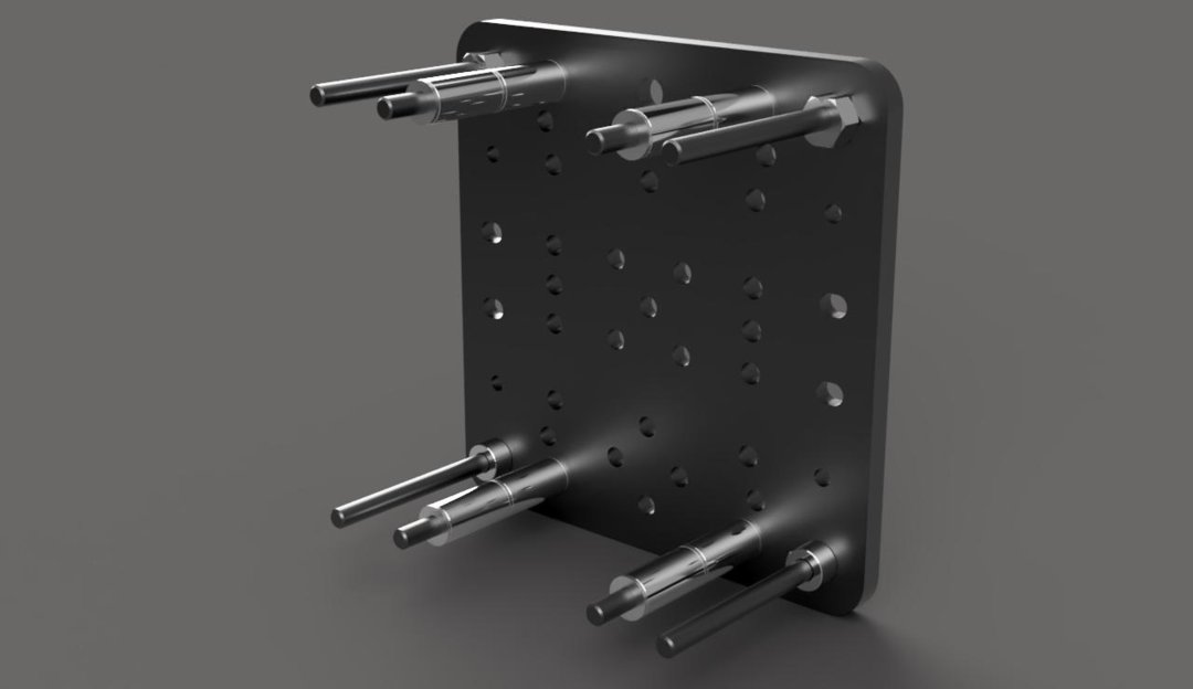
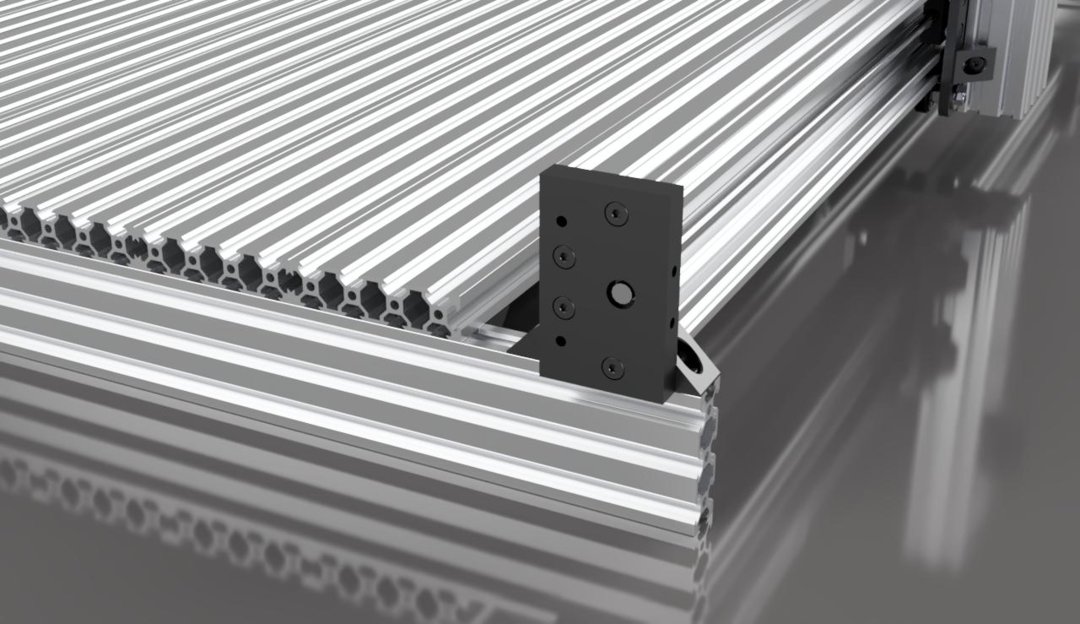
Using the tee nuts you inserted earlier, 20 corner connectors, and 40 M5x8mm screws, fasten the middle brace to the fixture plate in an alternating pattern as shown.

Flip your fixture plate assembly over. Insert 2 tee nuts into the top rail of the 20x60 extrusions on each of the 4 corners that are sticking out. These will be used later to attach the Y axis linear actuators.

Step 2
Gantry Plate Assemblies
Y Gantry Plate Assembly
(Make 2 of These)
Materials Needed:
- 2x - C-Beam Gantry Plate XL
- 16x - Ball Bearing 625 2RS 5x16x5
- 8x - Xtreme Solid V-Wheel
- 2x - Nut Block
- 4x - 3mm Aluminum Spacer
- 4x - 6mm Aluminum Spacer
- 4x - 9mm Aluminum Spacer
- 8x - 20mm Aluminum Spacer
- 4x - 6mm Eccentric Spacer
- 8x - M5x60mm Low Profile Screw
- 4x - M5x20mm Low Profile Screw
- 16x - M5x8mm Low Profile Screw
- 8x - M5 Nylon Insert Hex Locknut
- 20x - Precision Shim 10x5x1
- 4x - Slot Washer 15x5x2
- 8x - Black Angle Corner Connector
- 16x - Tee Nut
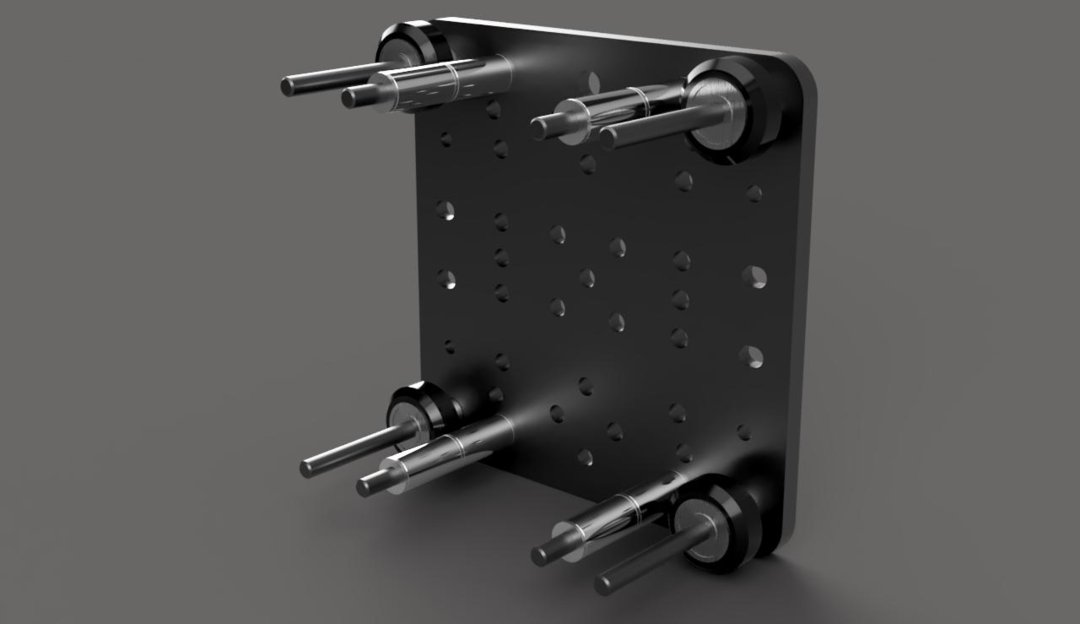
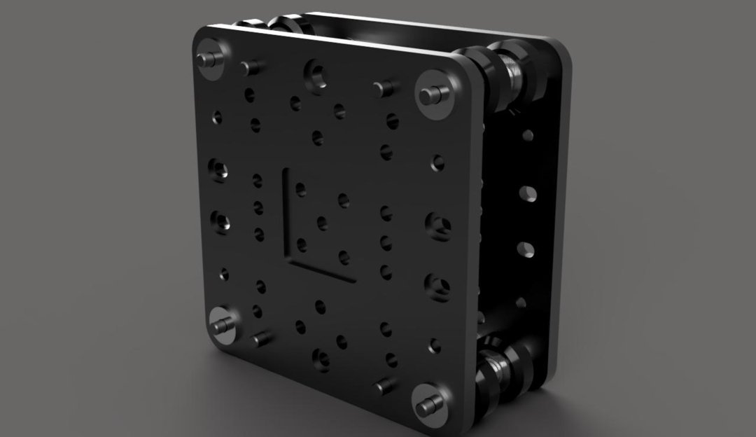
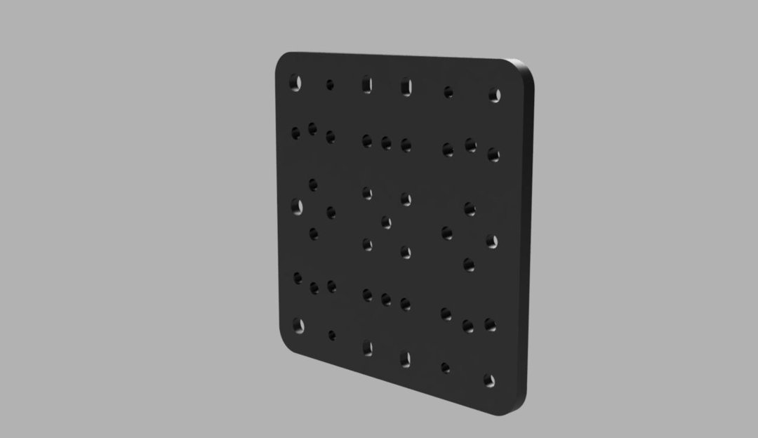
Stand 1 C-Beam gantry plate up with the square cutout facing away from you and the elongated holes on the left and right.
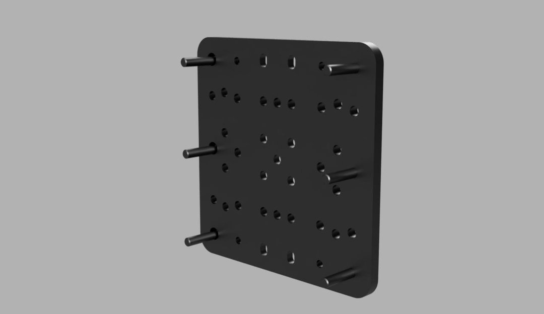
Insert 1 M5x60mm screw into each of the 4 corner holes. Insert M5x60mm screws into each of the holes next to those, toward the inside of the plate.
Carefully lay the plate down so that the screws are facing up.
Slide 1 precision shim onto each of the 4 inside screws, followed by a 20mm spacer, then another shim, another 20mm spacer, then, 1 last shim.


Notice that 2 of the outside corner holes are slightly larger than the other 2. These are the holes that will use the eccentric spacers instead of straight spacers in the next step.
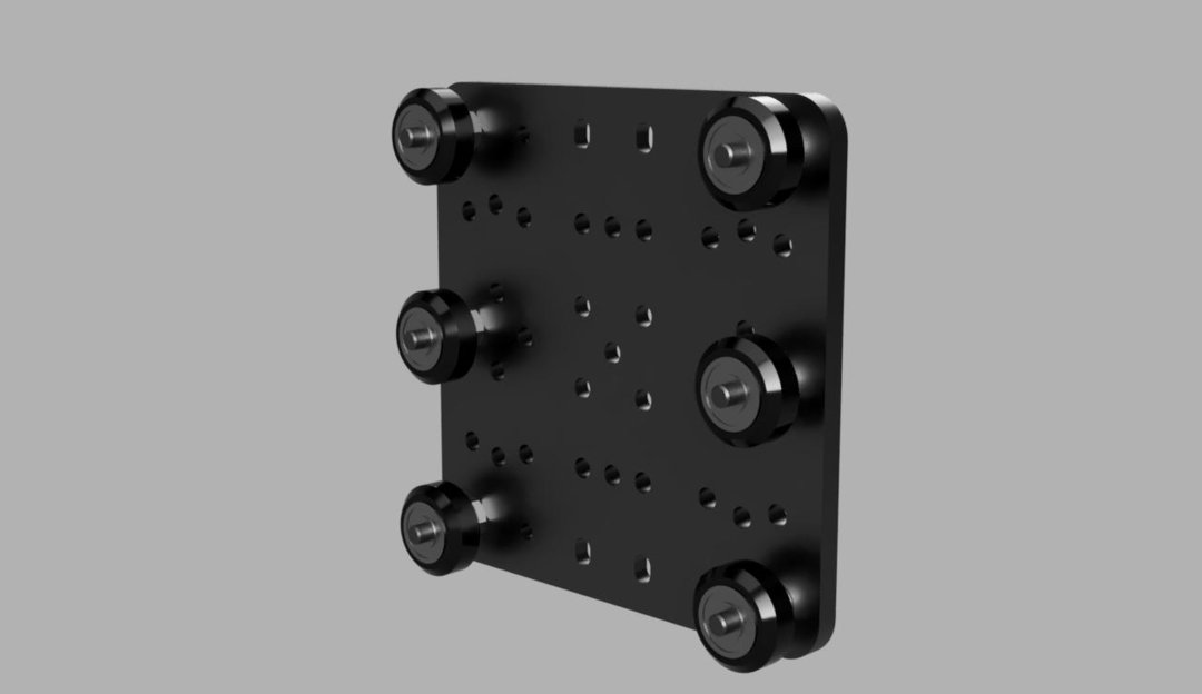
Slide 1 eccentric spacer onto each of the 2 screws that are in the larger holes. The eccentric spacers have a hex-side and a round side. Be sure to slide them on with the round side facing toward the plate. They should fit snugly into these holes. Slide 1 6mm spacer onto each of the other 2 screws.
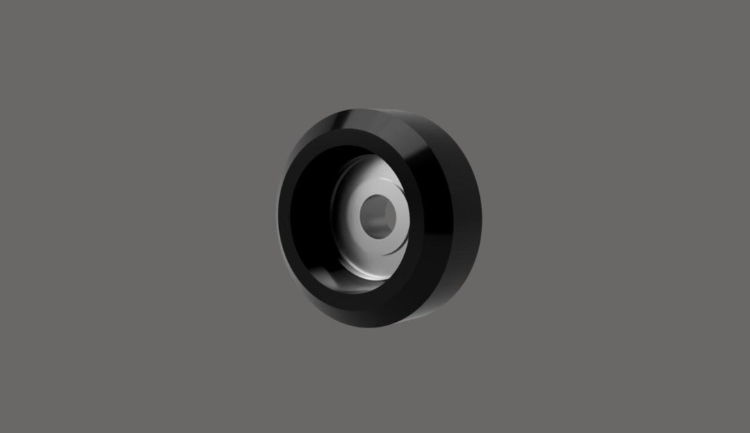
Each of the wheels are assembled in the same way. To assemble a wheel, press a 5x16x5 bearing into one side of a V-Wheel. Place a precision shim onto the bearing so that it will sit in the middle of the wheel. Press another 5x16x5 bearing into the other side of the wheel.


Place 1 wheel assembly onto each of the 4 corner screws. If you have trouble lining up the bearing holes with the shim hole, you can use a hex key or similar object to move the shim around inside the hole. Follow that with a 9mm spacer for each, then another wheel assembly.

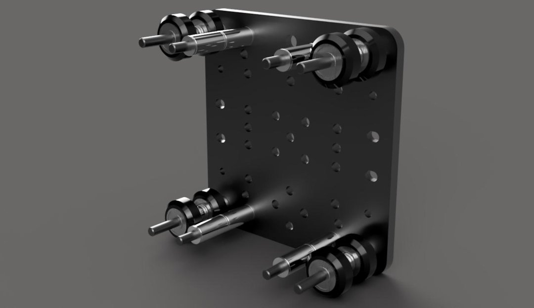
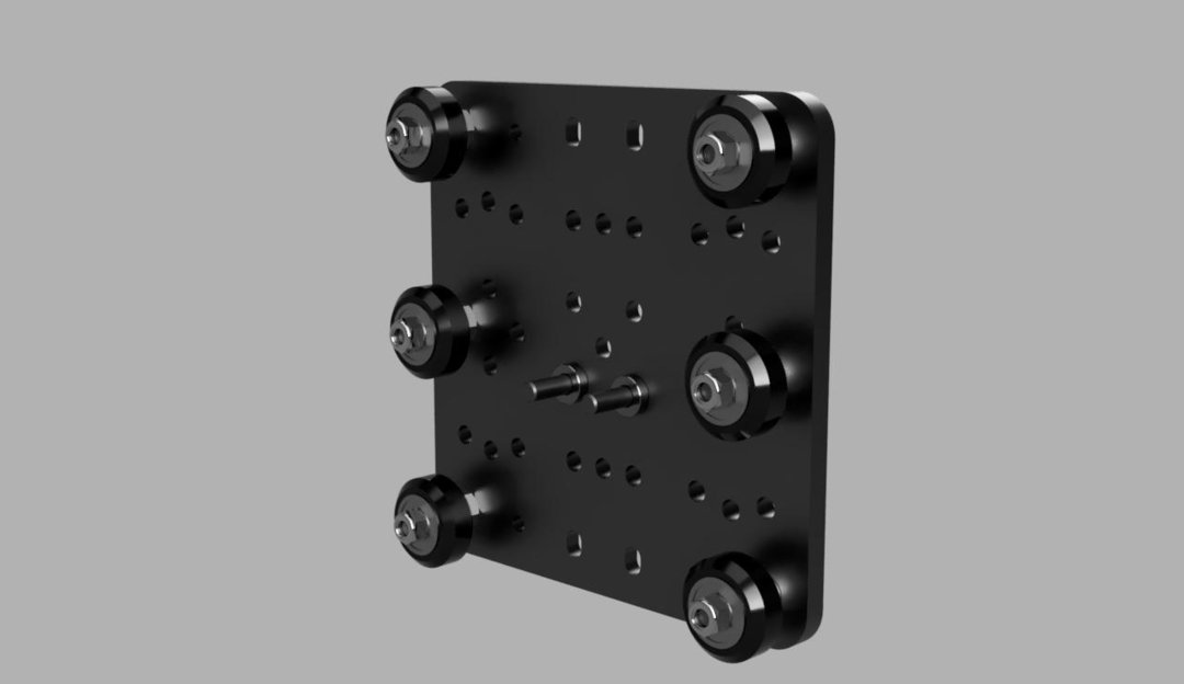
Place eccentric spacers onto the same screws that you placed eccentric spacers onto earlier, but with the round end facing up this time, so that it will fit into the top gantry plate. Place 6mm spacers onto the other 2 screws.
Place another C-Beam gantry plate on top, with the square cutout facing up and the elongated holes aligned with the first plate.
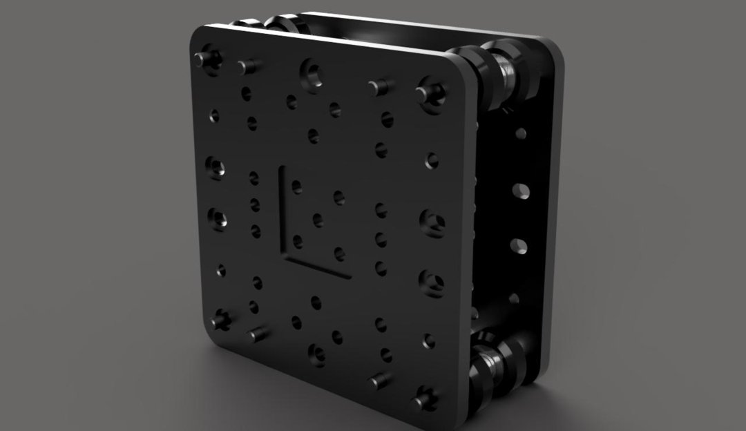
Place a slot washer on each of the 4 corner screws, followed by an M5 nylon locknut.
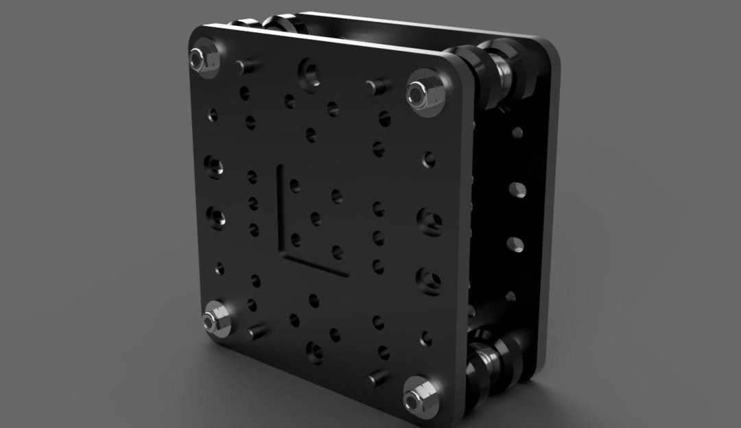
Add a tee nut to each of the 4 inner screws.
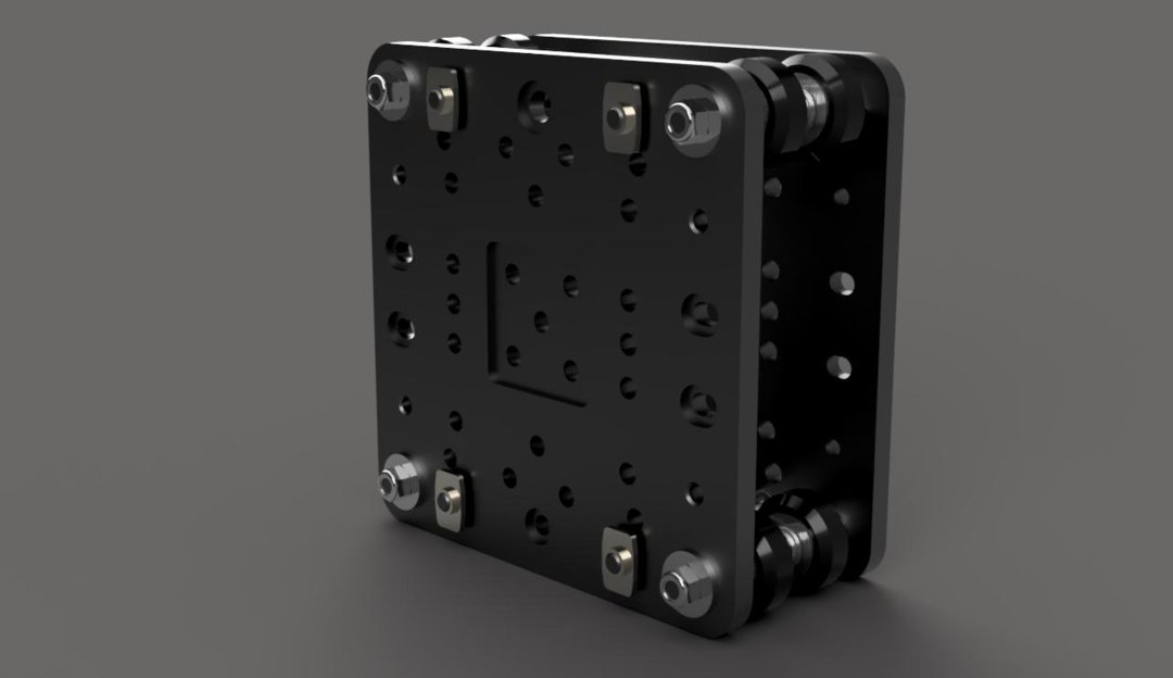
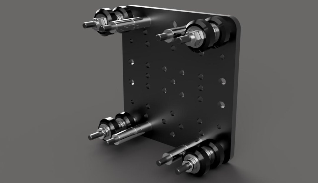
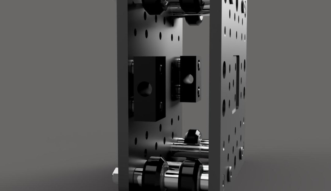
Insert an M5x20mm screw into each of the elongated holes on the side of the gantry plate with the nylon lock nuts.

On the other side of the plate, slide a 3mm spacer onto each of these screws. A nut block will now attach to each pair of these screws. Each nut block will need 2 nylon locknuts in the provided spaces to fasten to the M5x20mm screws. Do not tighten these screws all the way yet. The nut blocks should be able to slide from side to side fairly easily.

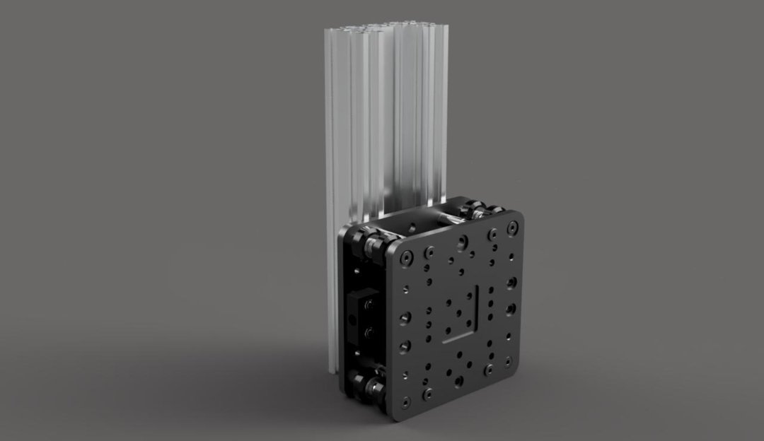
Slide a 250mm C-Beam extrusion onto these tee nuts on both assemblies, making sure they are flush with the bottom of the gantry plate, and tighten them into place. The opening of the C-Beam should face inward toward the plate.
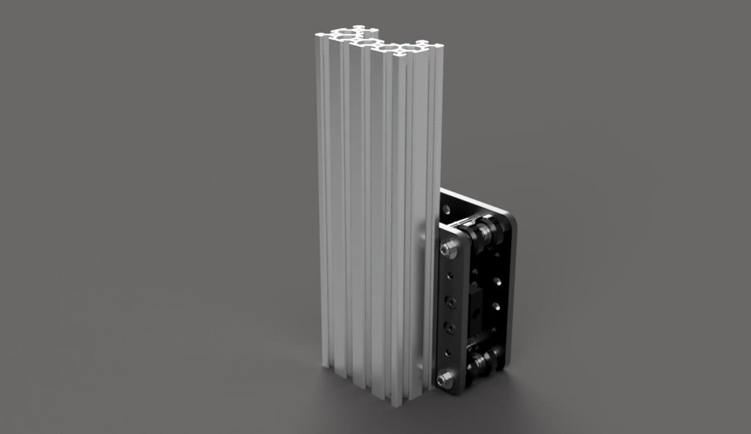
Slide a tee nut into the slot of the C-Beam you just attached that is closest to the gantry plate.

Attach a corner connector to this tee nut, using an M5x8mm screw. The other side of the corner connector will fasten to the gantry plate as shown. Repeat this process for the other 3 holes shown, and all 4 holes on the other Y axis gantry assembly.
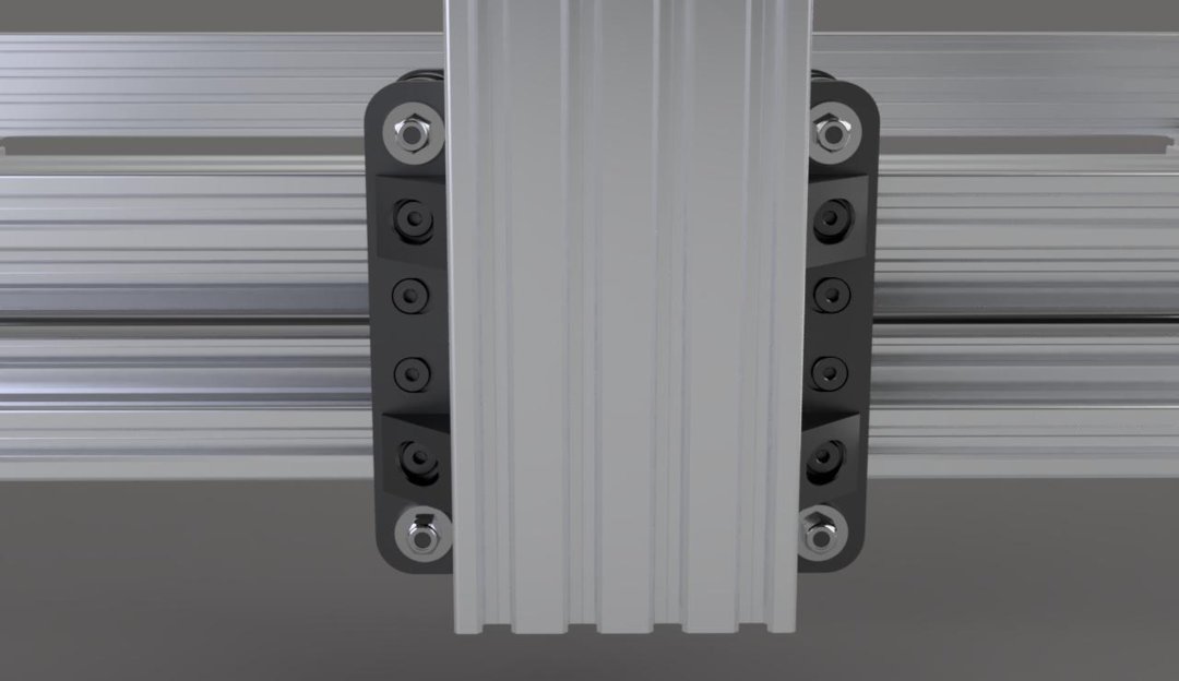
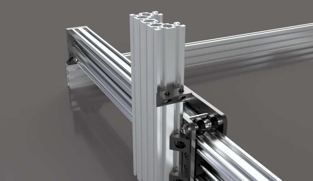
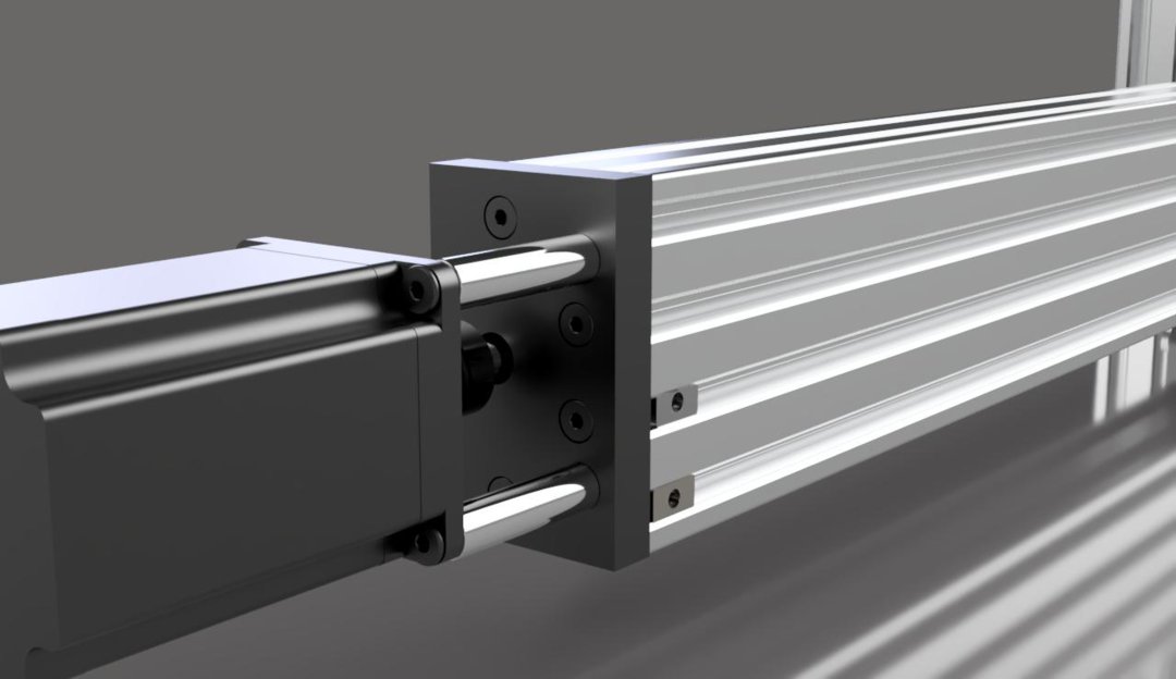
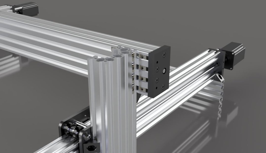
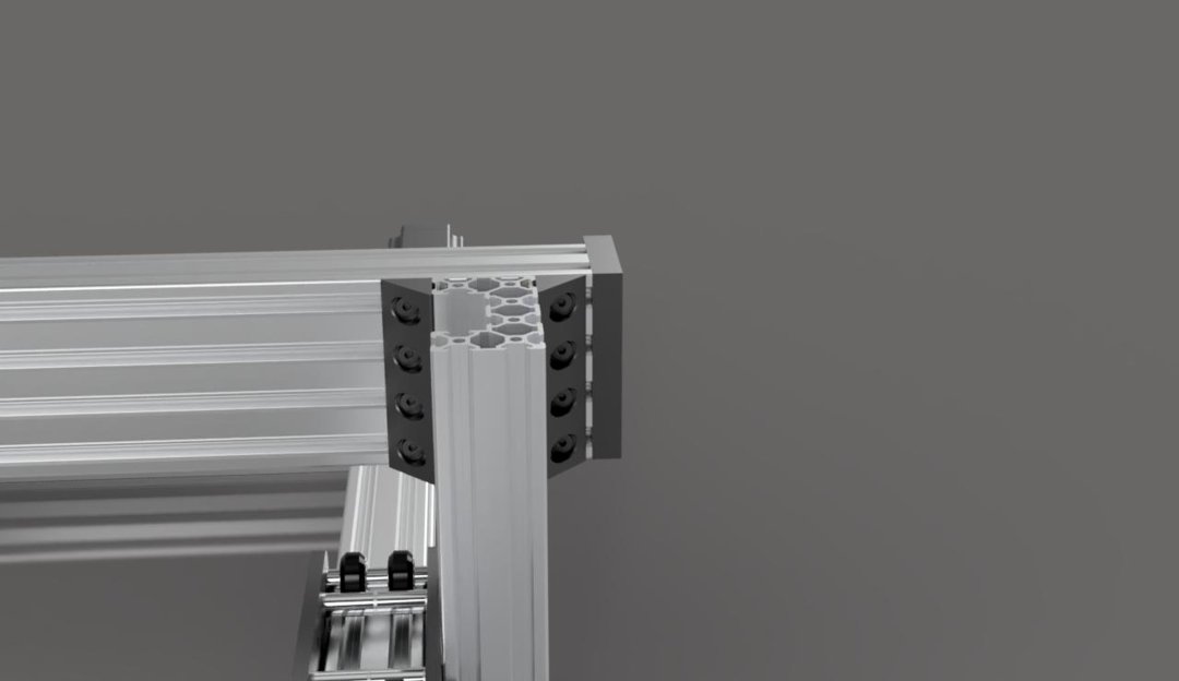
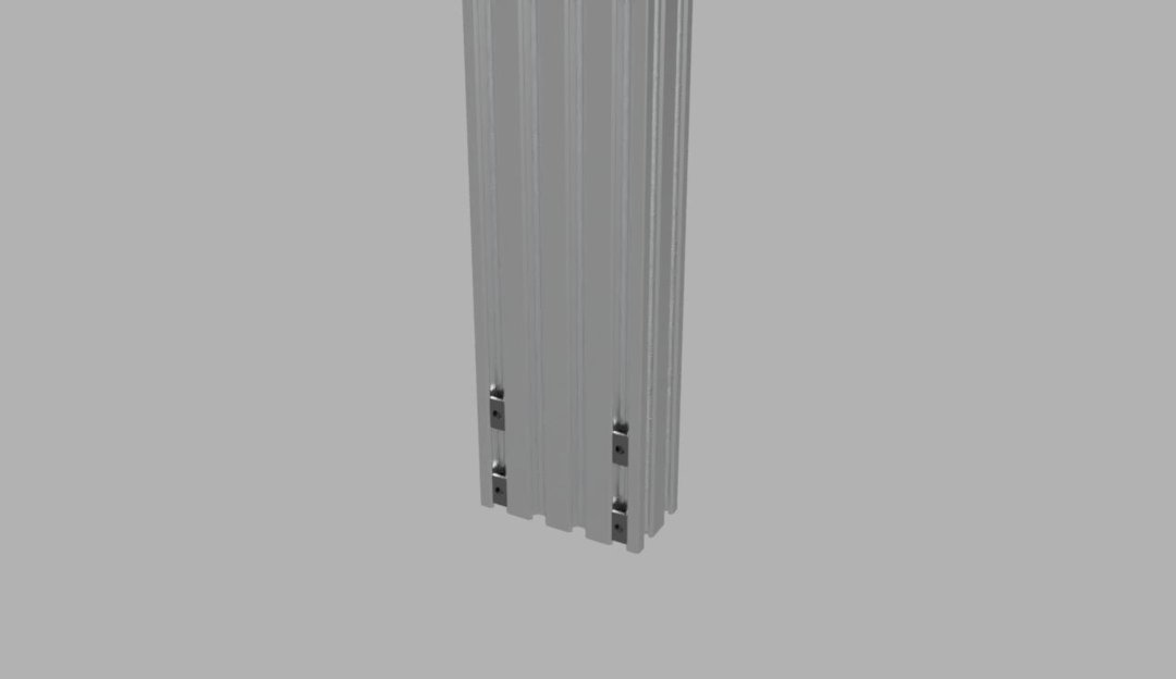
Slide a tee nut into each slot on the side of each extrusion (The side that faces the back of the machine).
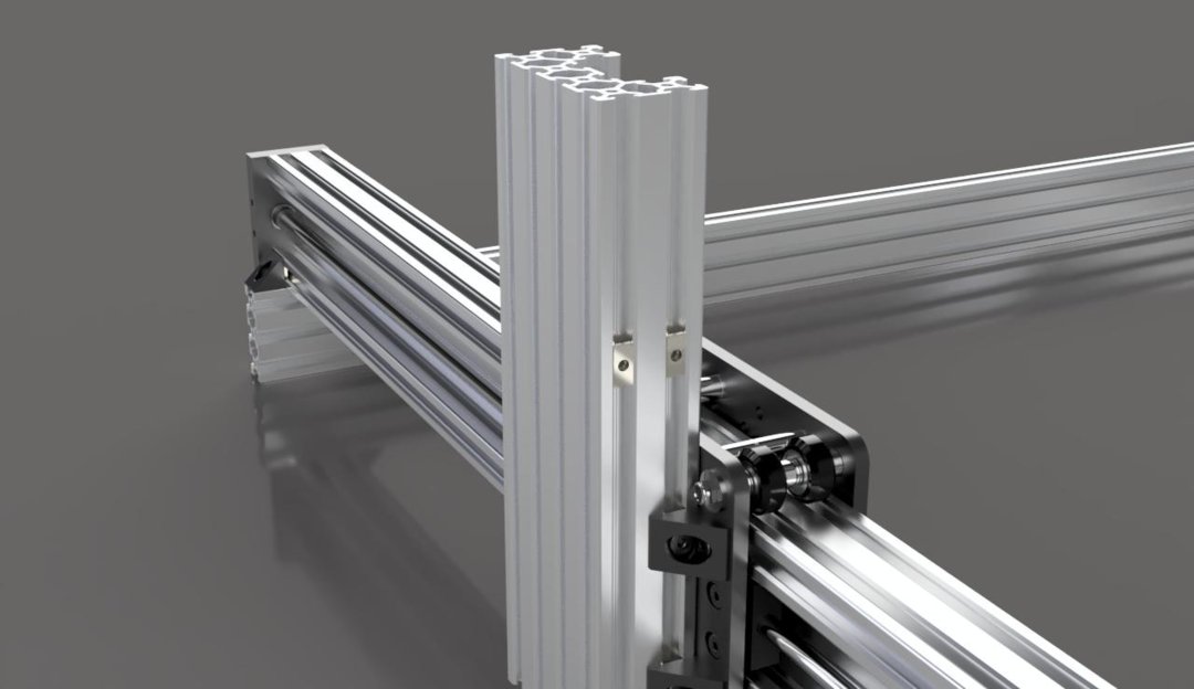
Attach a corner connector to each of these using M5x8mm screws. The flat part of the connector should be 80mm from the end of the extrusion.
X Gantry Plate Assembly
Materials Needed:
- 2x - C-Beam Gantry Plate XL
- 16x - Ball Bearing 625 2RS 5x16x5
- 8x - Xtreme Solid V-Wheel
- 2x - Nut Block
- 4x - 3mm Aluminum Spacer
- 4x - 6mm Aluminum Spacer
- 4x - 9mm Aluminum Spacer
- 8x - 20mm Aluminum Spacer
- 4x - 6mm Eccentric Spacer
- 8x - M5x60mm Low Profile Screw
- 4x - M5x20mm Low Profile Screw
- 16x - M5x8mm Low Profile Screw
- 8x - M5 Nylon Insert Hex Locknut
- 20x - Precision Shim 10x5x1
- 4x - Slot Washer 15x5x2
- 8x - Black Angle Corner Connector
- 16x - Tee Nut
Stand 1 C-Beam gantry plate up with the square cutout facing away from you and the elongated holes on the left and right.
Insert an M5x60mm screw into each of the 4 corner holes so that the screw heads are on the same side as the cutout on the gantry plate. Do not put more screws in the holes next to them. They will need to go in later on.

Slide the spacers, eccentric spacers, wheels, etc. on the same way you did for the Y axis assemblies.


Attach the other gantry plate with washers and nuts, same as the Y axis again.

Attach the nut blocks in the same way also.

Now, add the same spacer assemblies from the Y axis, but make sure that the screws go in from the opposite side. These will need to be assembled one at a time.
Z Axis Gantry Plate Assembly
Materials Needed:
- 2x - M5x20mm Low Profile Screw
- 6x - M5x25mm Low Profile Screw
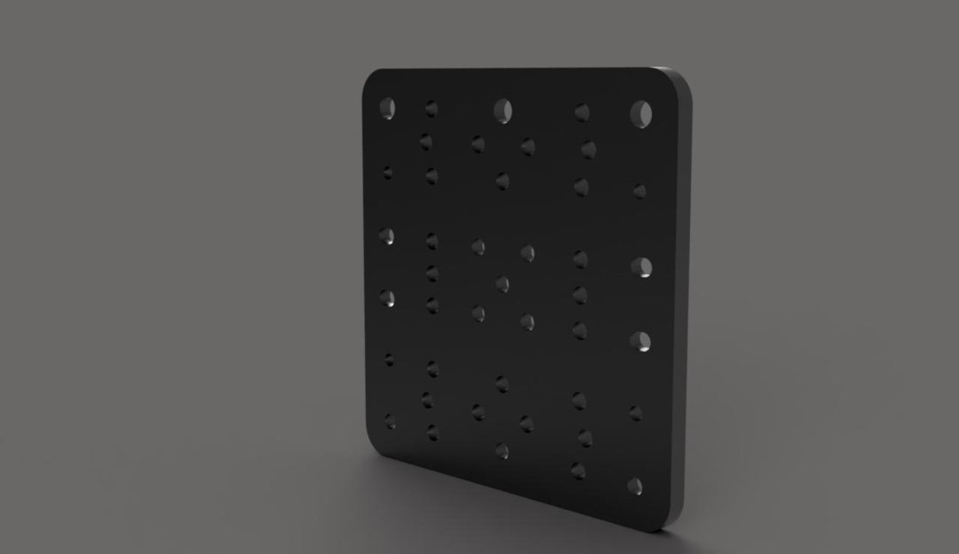
- 1x - C-Beam Gantry Plate XL
- 4x - M5x10mm Low Profile Screw
- 6x - Xtreme Solid V-Wheel
- 6x - Precision Shim 10x5x1
- 8x - M5 Nylon Insert Hex Locknut
- 12x - Ball Bearing 625 2RS 5x16x5
- 3x - Eccentric Spacer
- 3x - 6mm Aluminum Spacer
- 2x - 3mm Aluminum Spacer
- 1x - Anti-Backlash Nut Block
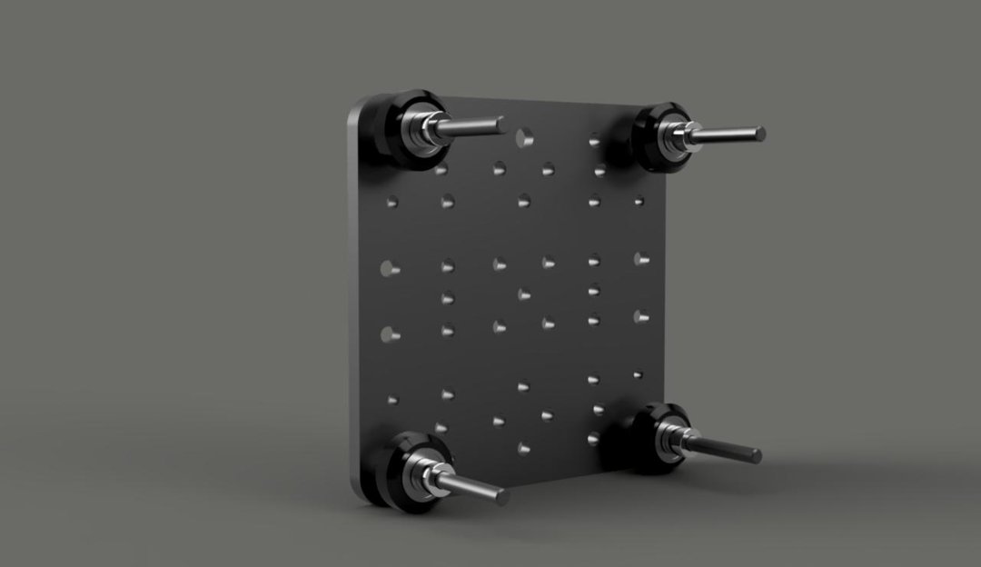
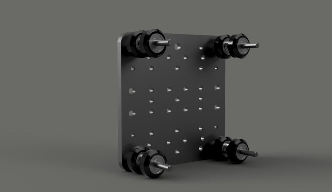
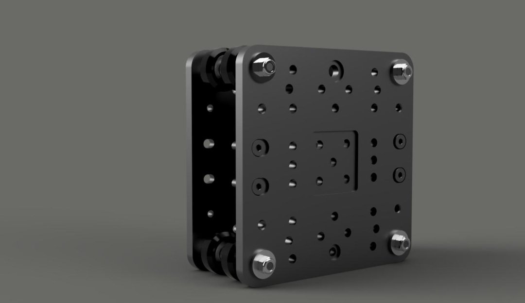
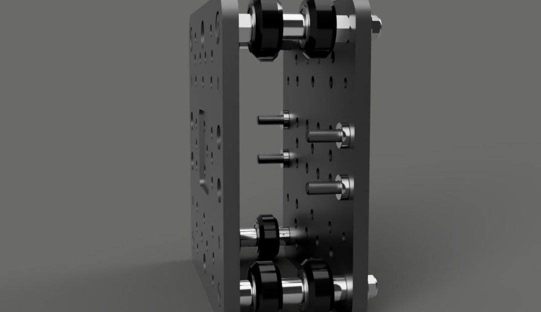
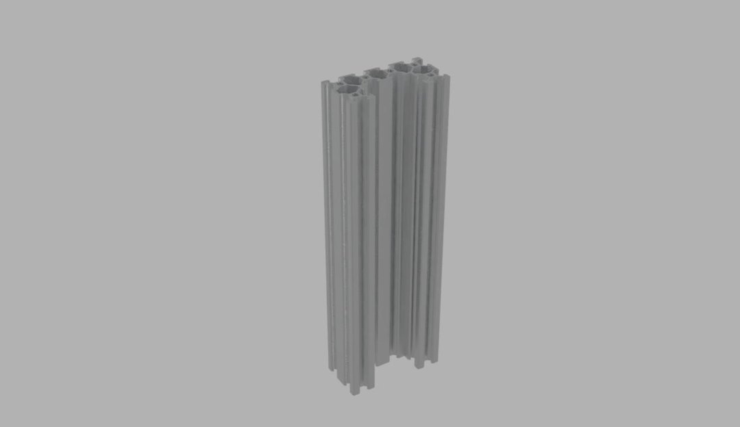
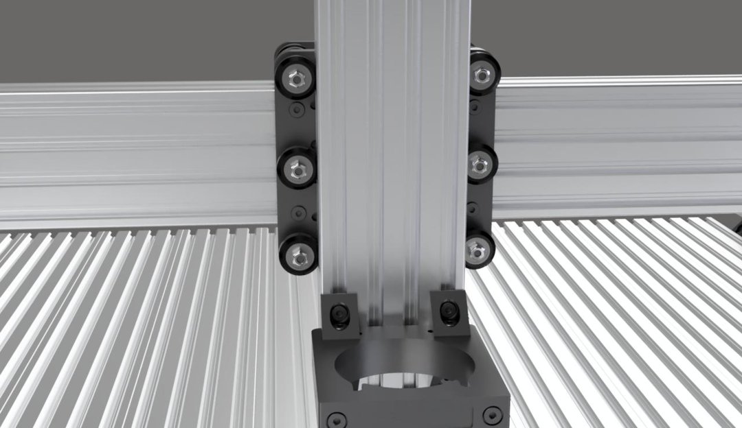
Start with a gantry plate, with the middle square cutout facing away from you and the elongated holes aligned vertically.
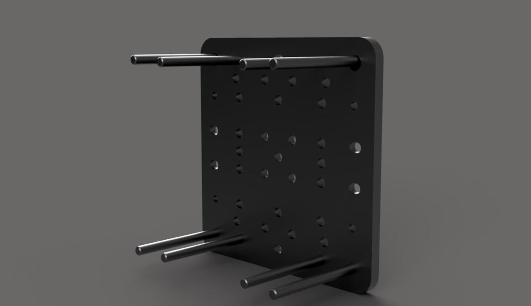
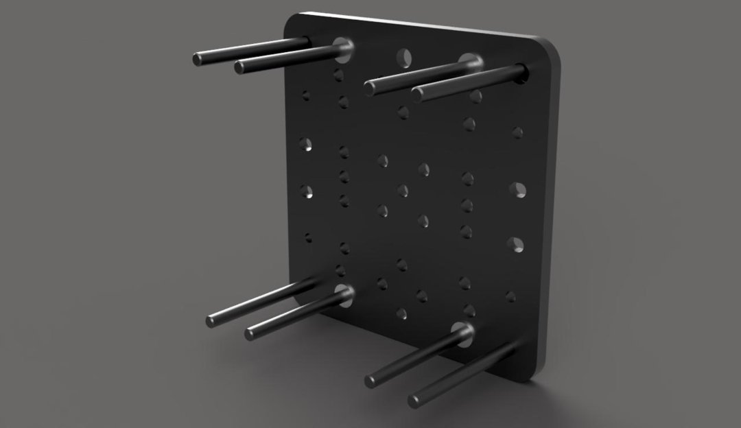
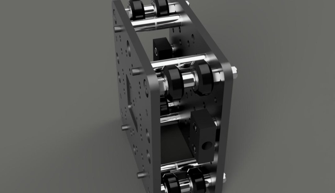
Insert an M5x25mm screw into each of the 6 outside holes in the gantry plate with the screw heads on the same side as the nut block screws. For each of the 3 screws in the larger holes, insert an eccentric spacer with the round side toward the plate. The round side of the spacer will fit into the holes. For the other 3 screws, add a normal 6mm spacer.

Add a wheel assembly to each screw. If you have not assembled all of the wheels at this point, the order is 5x16x5 bearing, V-wheel, precision shim, and another bearing.
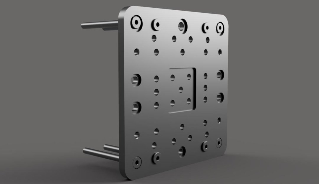
Finish all six of the wheels off with an M5 locknut.

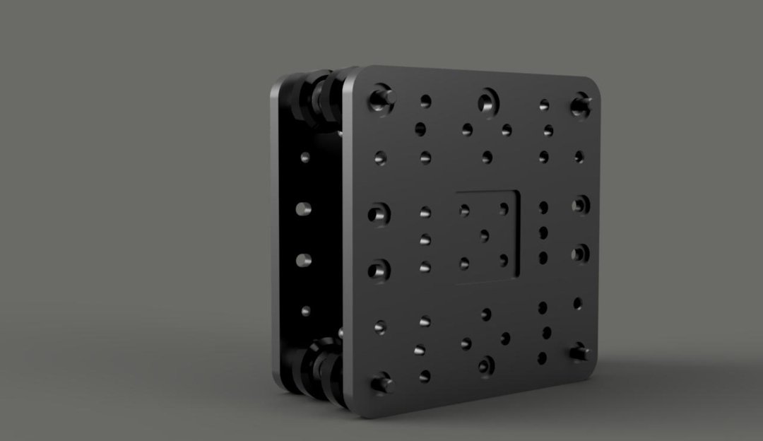
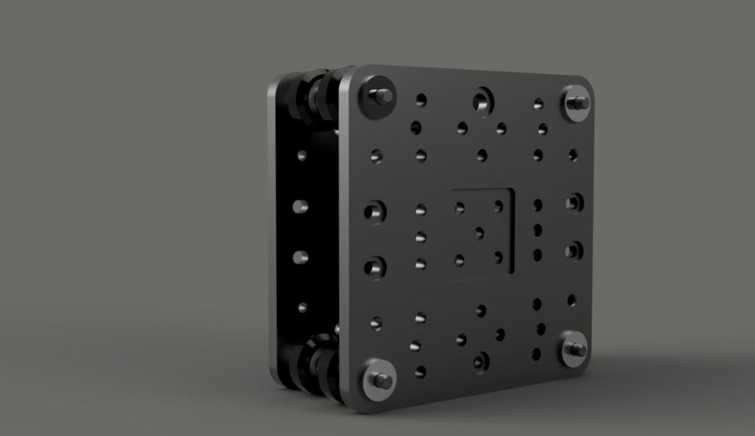
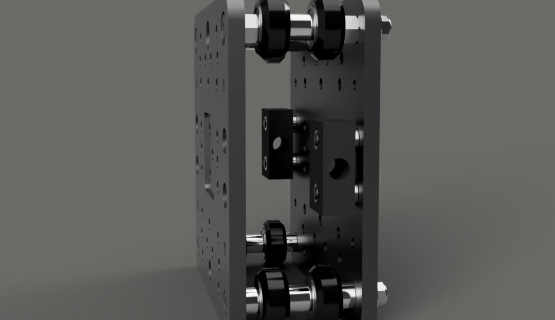
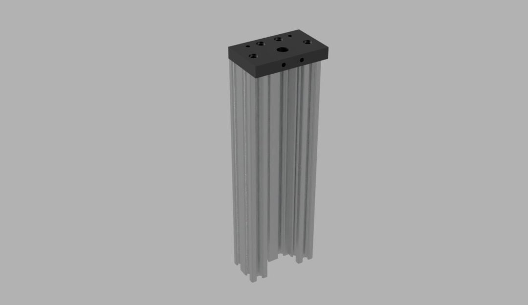
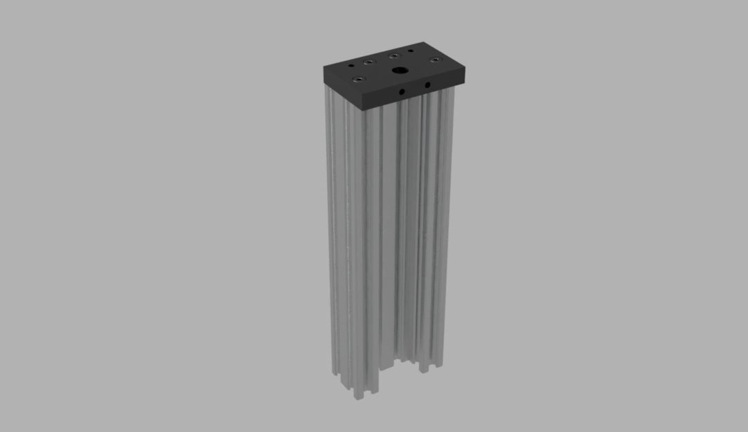
Insert 2 M5x20mm screws into the bottom 2 holes of the square cutout so that the heads of the screws sit inside the cutout. Slide a 3mm spacer onto each of these screws, followed by the anti-backlash nut block, and tighten them into place with an M5 locknut in each of the cutouts on the nut block.


Insert 4 M5x8mm screws into the holes shown below.
Insert the set screw that came with your anti-backlash nut. Screw a lead screw into the nut and adjust the set screw until there is no play in the nut. Tighten the nut that came with the nut block onto the set screw to hold it in place. Remove the lead screw.
Step 3
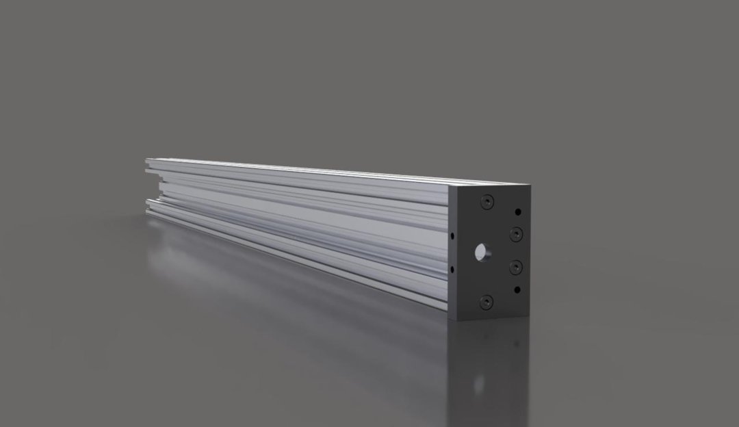
Linear Actuators
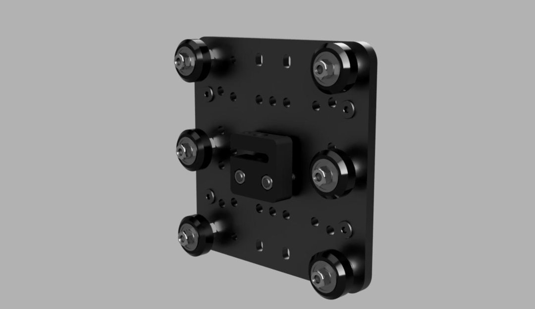
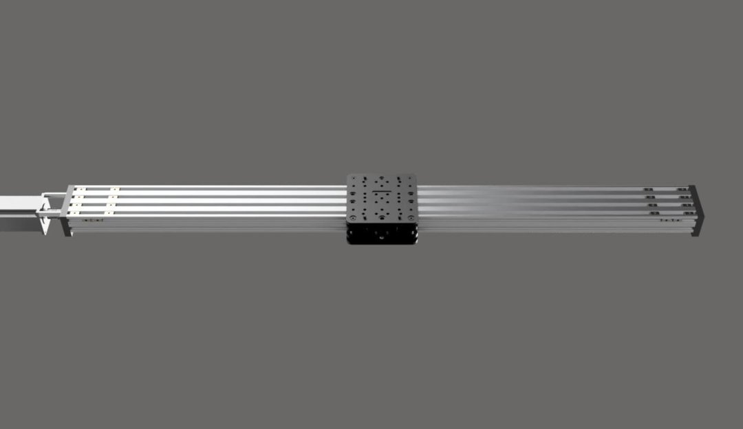
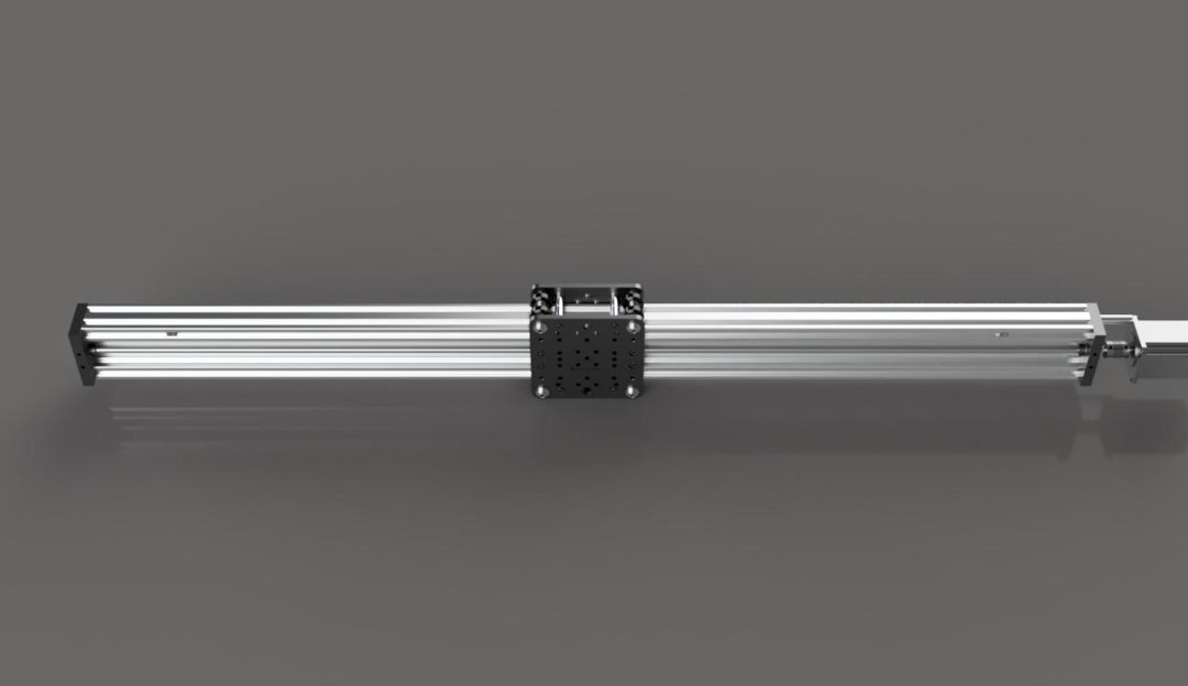
Y Axis Linear Actuator
(Make 2 of These)
Materials Needed:
- 1x - 1000mm C-Beam Extrusion
- 2x - C-Beam End Mount
- 1x - 12x8x1mm Shim
- 2x - 40mm Aluminum Spacer
- 1x - 1000mm Acme Lead Screw
- 2x - M5x55mm Low Profile Screw
- 1x - 8mm Lock Collar
- 1x - Bearing 688Z 8x16x5
- 1x - Nema 23 Stepper Motor
- 1x - ¼”x8mm Flexible Coupling
- 1x - Y Gantry Plate
- 20x - M5x8mm Low Profile Screw
- 12x - Tee Nut
Fasten a C-Beam end mount to 1 end of the C-Beam extrusion using 4 M5x20mm screws.
Left:
Right:
Left:
Right:
Slide the gantry plate assembly onto the C-Beam extrusion. Be sure to check the orientation of each one according to the pictures below.
Left:
Right:
Slide 2 tee nuts into each bottom slot of both actuators as shown. For the actuator that will be on the right side of the machine, also add 2 more tee nuts to the next slot up on the inside wall.
Left:
Right:
Fasten another C-Beam end mount to the other end of the extrusion, using 4 more M5x20mm screws.
Insert the lead screw into 1 of the end mounts, but don’t attach it to the gantry plate assembly yet. Slide an 8x16x5 bearing onto the lead screw, followed by a 12x8x1 shim washer, then a lock collar. Do not tighten the lock collar into place yet.
Left:
Right: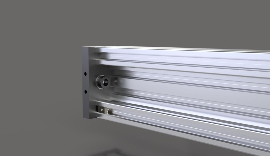
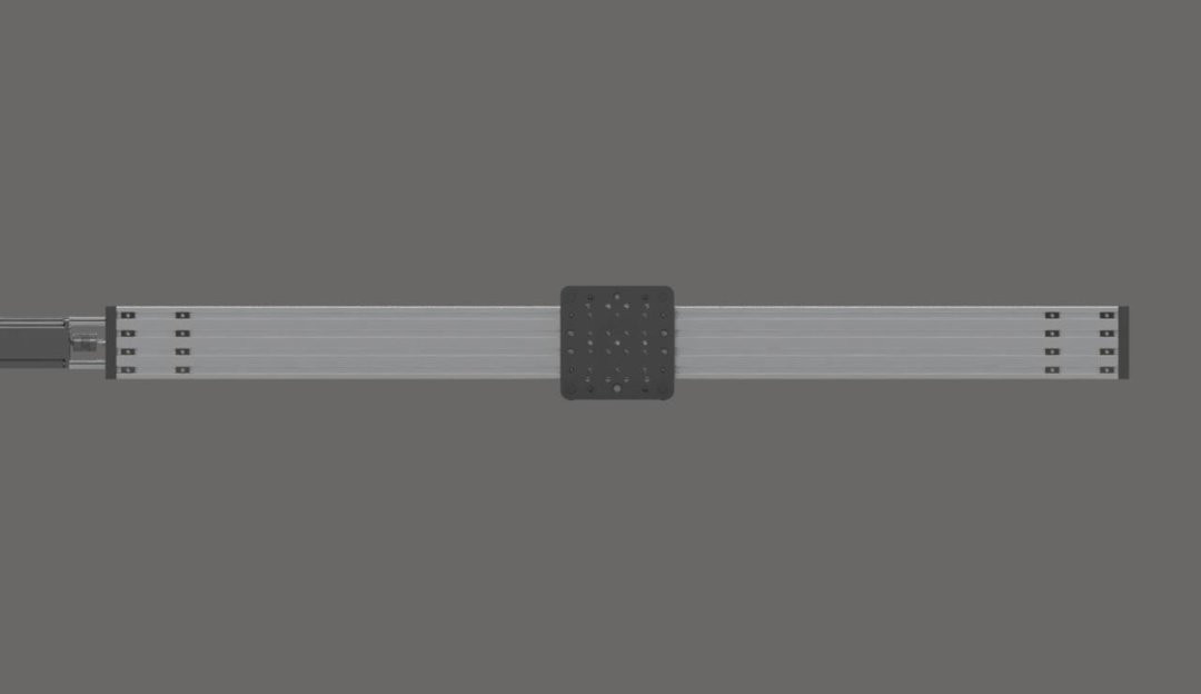
Thread the lead screw into one of the nut blocks. Pull the nut block to one side and tighten it into place. Continue to thread the leadscrew through to the second nut block. With the nut block attached to the lead screw, slide the nut block to one side and tighten it into place. This will keep tension between the 2 nut blocks and help to avoid backlash when the machine is moving.
Keep threading the lead screw through, but don’t go through the other end mount yet. First, slide on another lock collar, followed by a 12x8x1 shim washer, followed by an 8x16x5 bearing. Do not tighten the lock collar yet.
Left:
Right:

Screw the lead screw through the second end mount until the other side is flush with the outside of the first end mount. Press the bearing into the end mount, then apply pressure toward the bearing with the lock collar and shim washer. Tighten the lock collar into place.
Press the other bearing into the other end mount. While applying a small amount of pressure on the lead screw toward the already tightened side, tighten the lock collar up against the bearing.
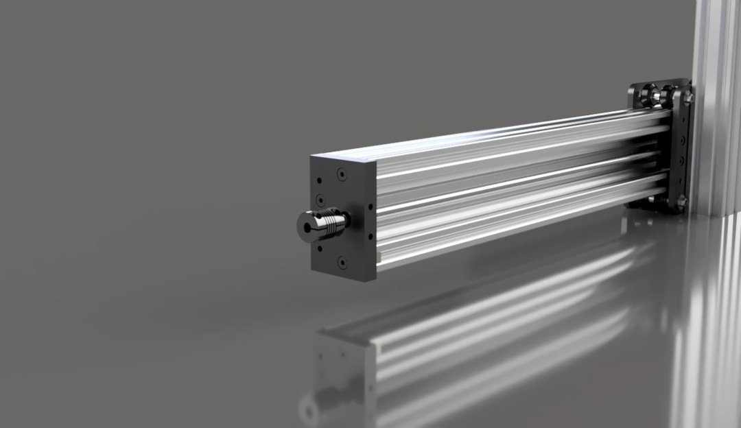
Attach a flexible coupling the end of the lead screw and tighten the set screw on the side to clamp it into place. The lead screw should be inserted a little less than halfway into the coupling.
Left:
Right:
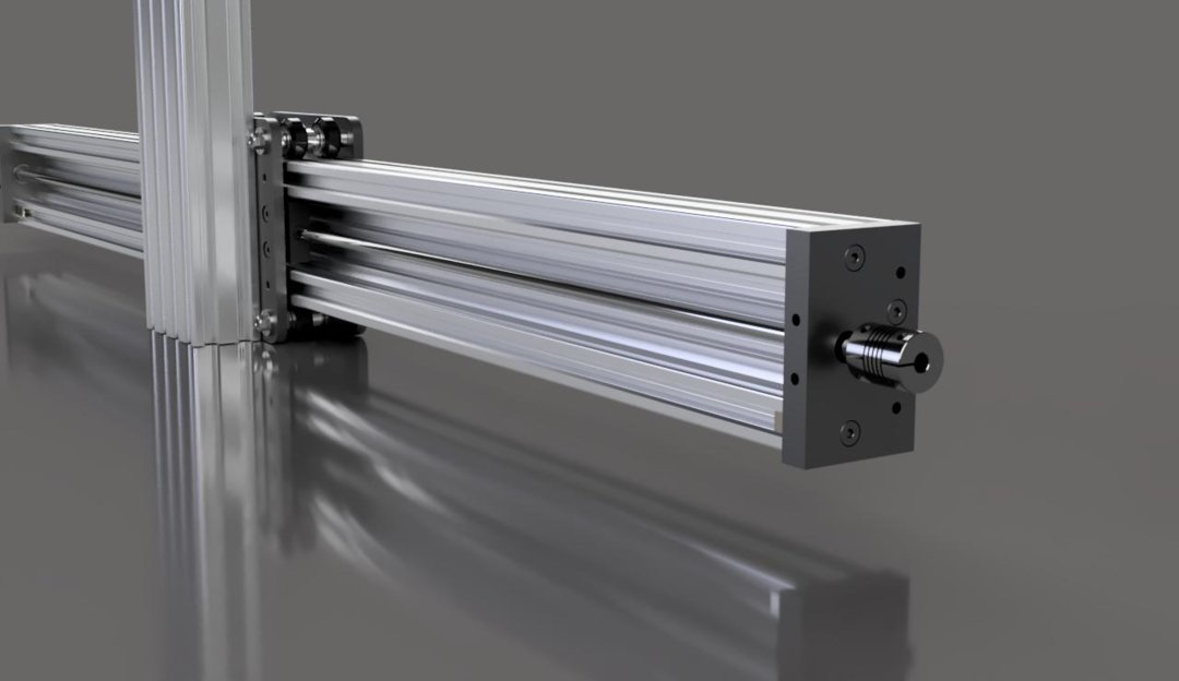
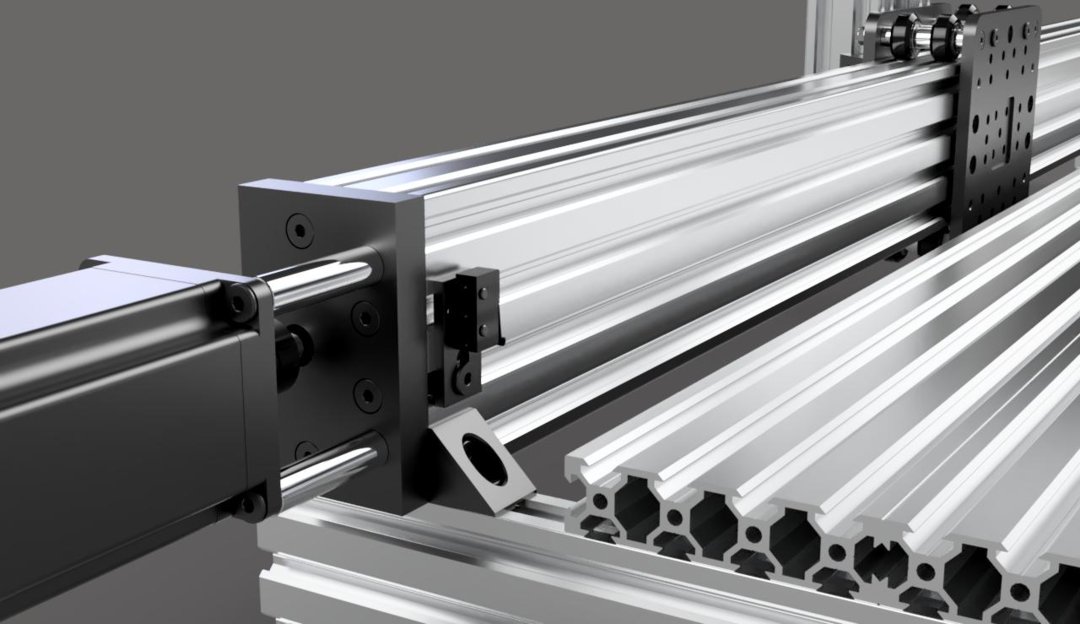
Using 2 M5x55mm screws and 2 40mm spacers, attach a Nema 23 stepper motor to the outside of this C-Beam end mount, making sure to insert the shaft of the motor into the coupling’s other side. Tighten the set screw on this side of the coupling.
Left:

Right:
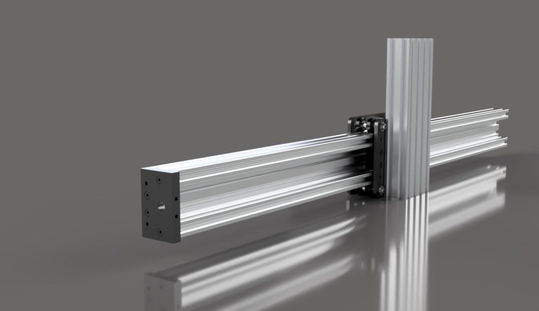
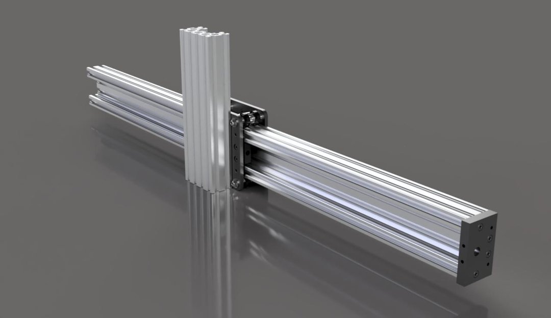
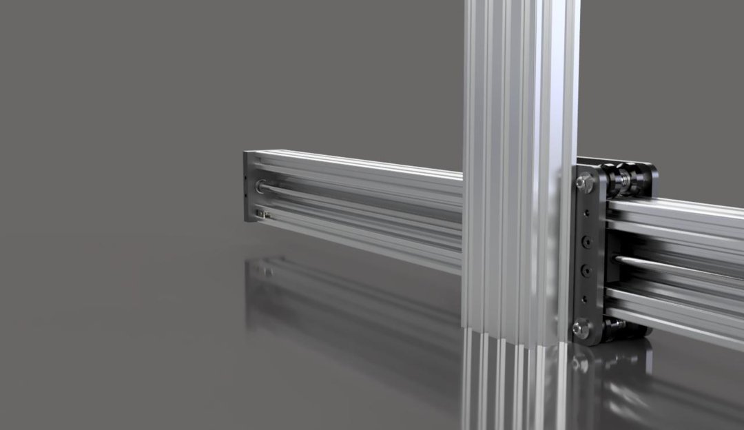
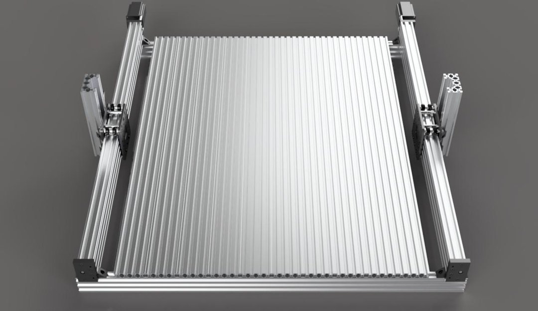
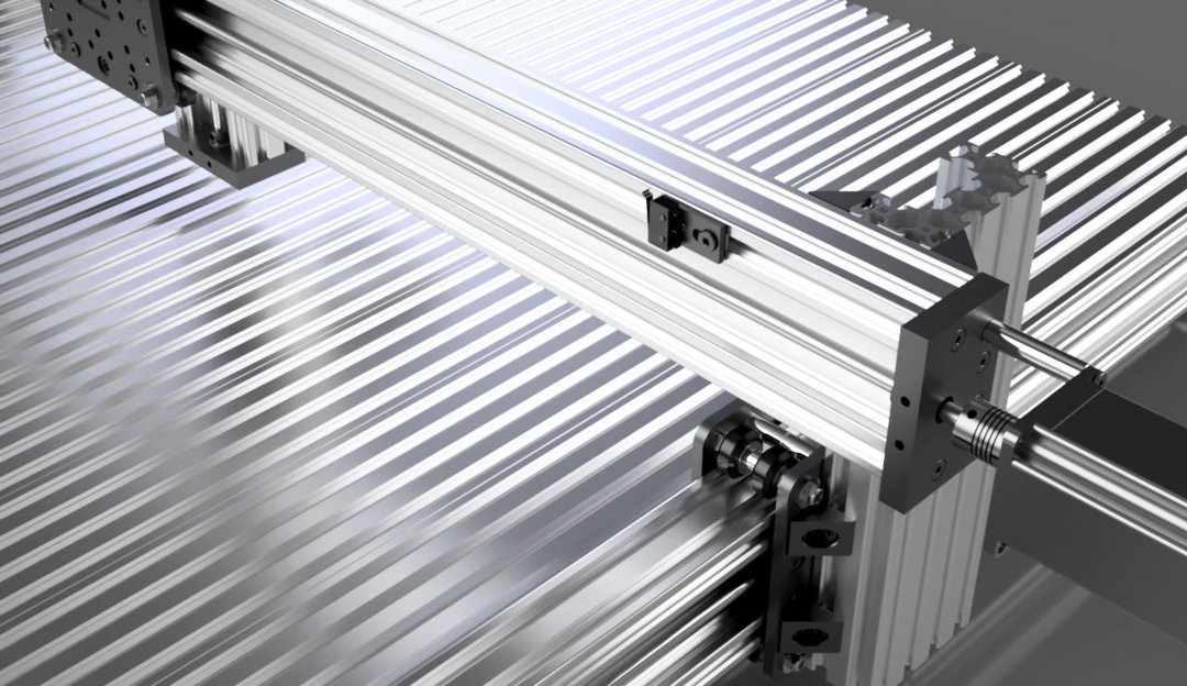
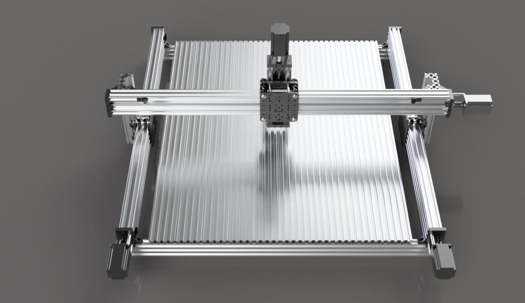
Attach the actuators to the fixture plate as shown.
X Axis Linear Actuator
Materials Needed:
- 1x - 1500mm C-Beam Extrusion
- 2x - C-Beam End Mount
- 2x - 12x8x1mm Shim
- 2x - 40mm Aluminum Spacer
- 1x - 1140mm Acme Lead Screw
- 2x - M5x55mm Low Profile Screw
- 2x - 8mm Lock Collar
- 2x - Bearing 688Z 8x16x5
- 1x - Nema 23 Stepper Motor
- 1x - ¼”x8mm Flexible Coupling
- 1x - X Gantry Plate
- 4x - M5x8mm Low Profile Screw
- 20x - Tee Nut
Start by marking the 1500mm C-Beam extrusion at 1100mm. This extrusion must be cut to this length. The holes in that end will also need to be tapped again, unless you have decided to go with self tapping M5x20mm screws for this.
Attach an end mount with 4 screws the same way as with the Y axis.
Slide the X gantry plate assembly on so that the exposed screws are toward the front of the machine.
Slide 4 tee nuts into each of the slots on the back side of the extrusion, 2 tee nuts into the top slot of the back of the extrusion, and 4 tee nuts into the bottom slot of this extrusion as shown.
Attach the bearings, shims, lock collars, lead screw, coupling, and motor the same way as the Y axis was done.
Using corner connectors and M5x8mm screws, attach the X actuator to the Y actuators as shown.
Z Axis Linear Actuator
Materials Needed:
- 1x - 250mm C-Beam Extrusion
- 2x - C-Beam End Mount
- 2x - 12x8x1mm Shim
- 2x - 40mm Aluminum Spacer
- 1x - 250mm Acme Lead Screw
- 2x - M5x55mm Low Profile Screw
- 2x - M5x25mm Low Profile Screw
- 8x - M5x20mm Low Profile Screw
- 2x - 8mm Lock Collar
- 2x - Bearing 688Z 8x16x5
- 1x - Nema 23 Stepper Motor
- 1x - ¼”x8mm Flexible Coupling
- 1x - Z Gantry Plate
- 4x - Black Angle Corner Connector
- 1x - Router/Spindle Mount
- 8x - M5x8mm Low Profile Screw
- 5x - Tee Nut
Start with the 250mm C-Beam extrusion.
Attach 1 end mount using 4 M5x20mm screws.
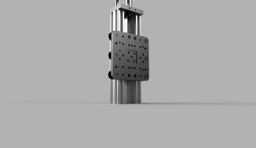
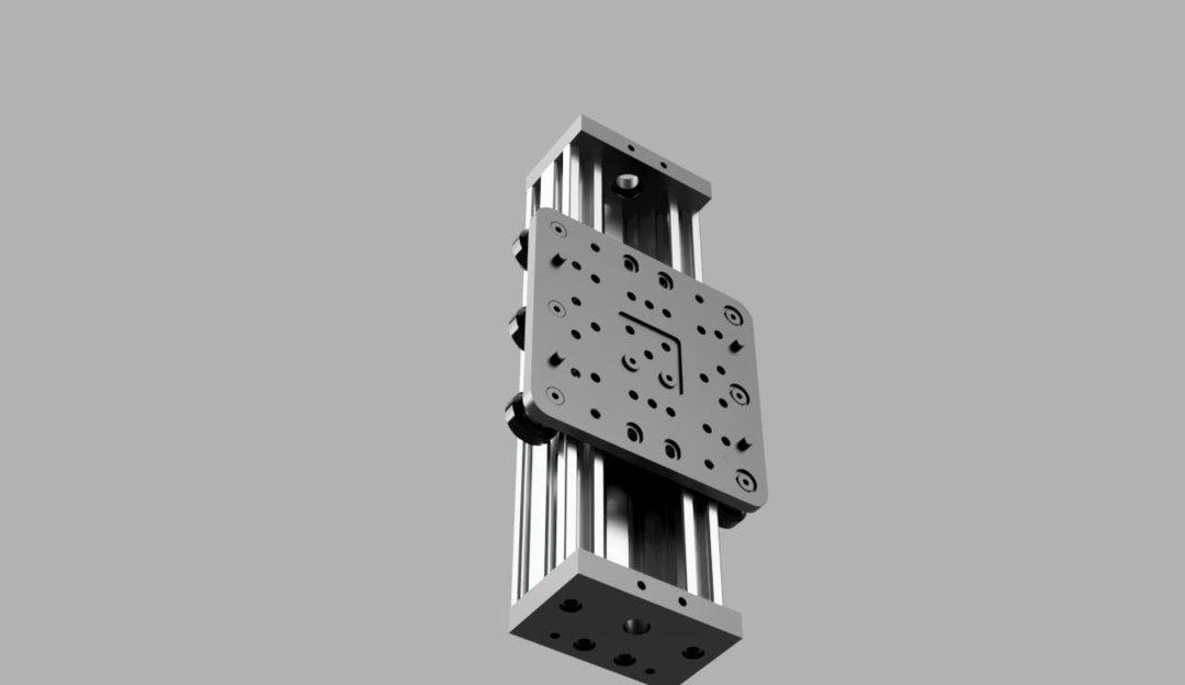
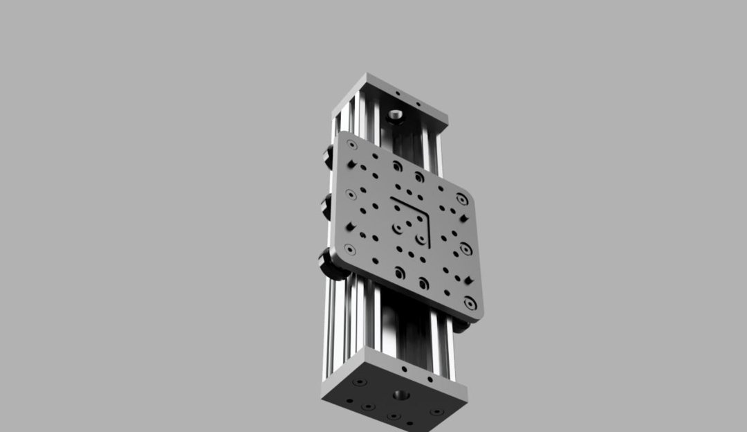
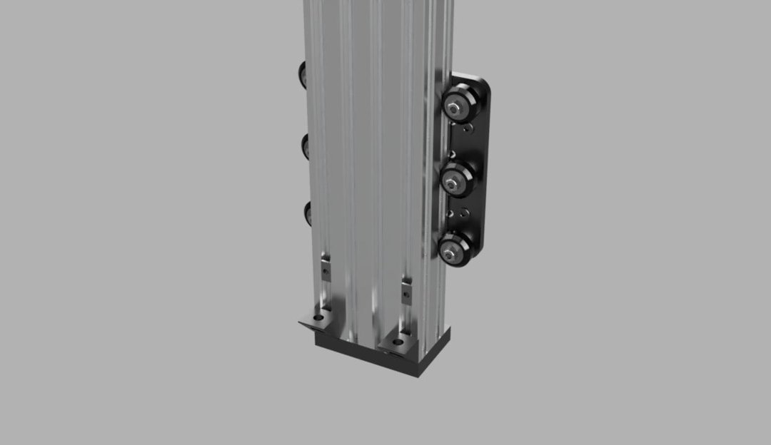
Slide the Z axis gantry assembly onto the extrusion.
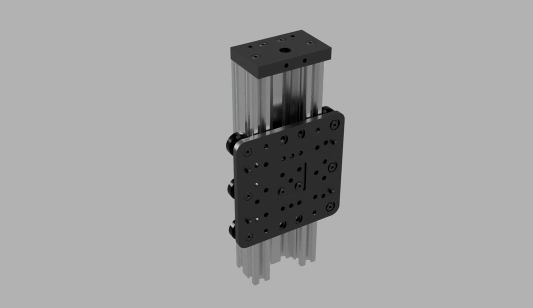
Slide 4 tee nuts into each of the outside slots on the back of the extrusion, and 1 tee nut into one of the front slots as shown.
Attach the other end mount.
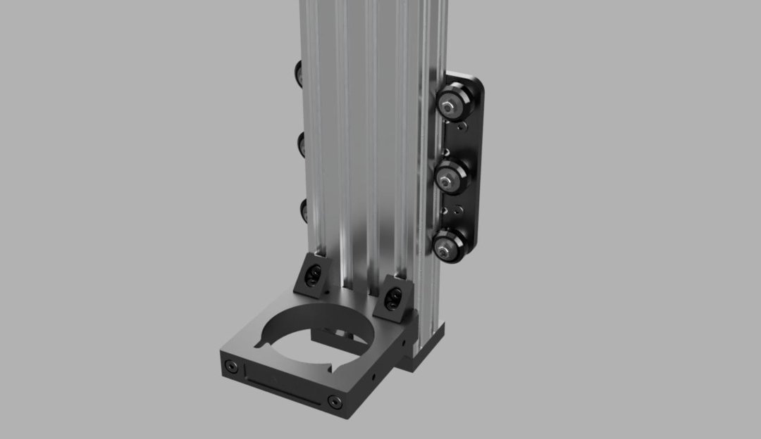
Attach the router/spindle mount to the back of the extrusion using corner connectors and M5x8mm screws.
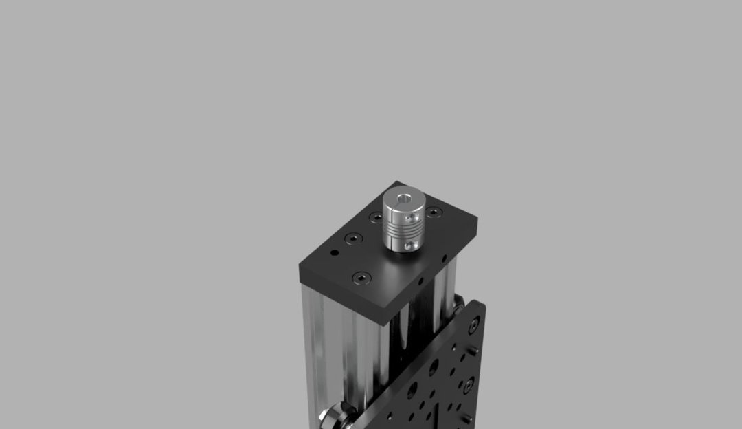
The rest of the actuator is assembled the same way as the rest of them have been.
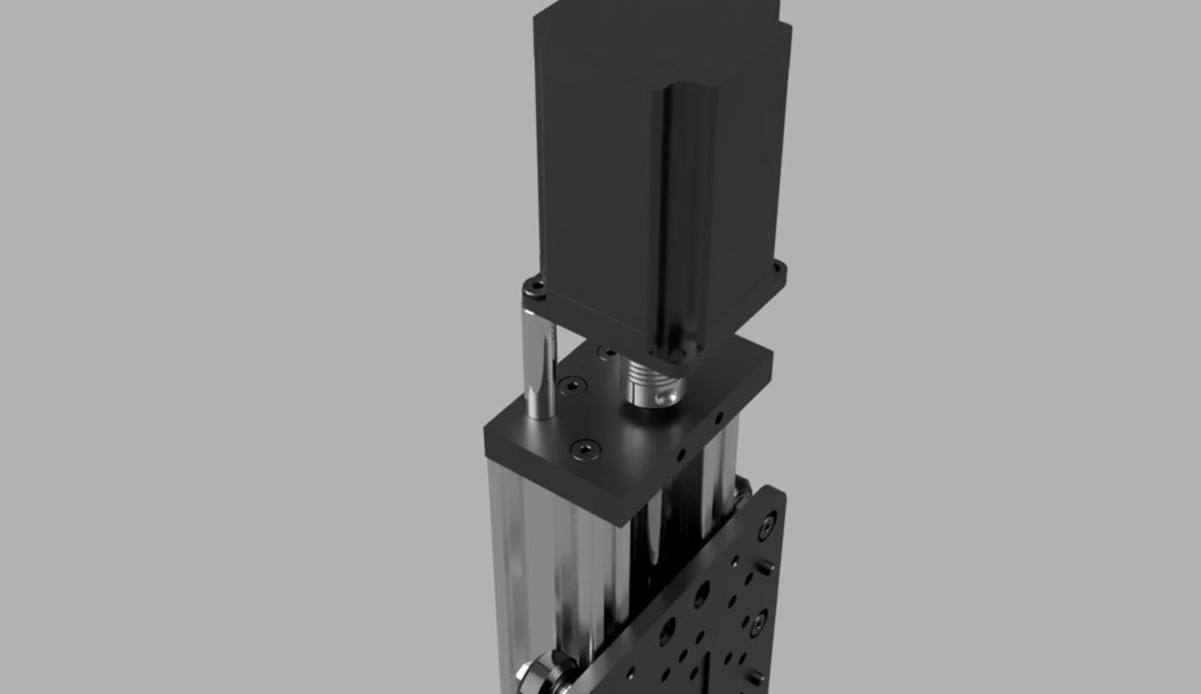
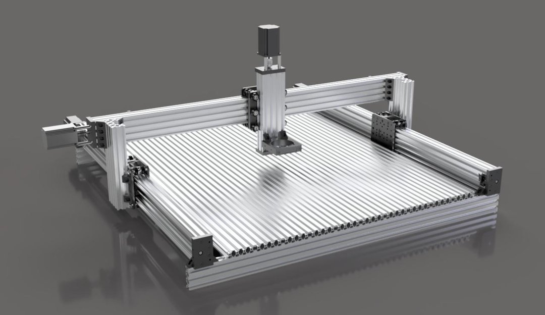
Attach the Z actuator assembly to the X gantry assembly using 4 M5x8mm screws and the 4 screws from the X gantry spacer assemblies.
Step 4
Limit Switches
Materials Needed:
- 5x - Micro Limit Switch
- 5x - Limit Switch Plate
- 10x - M3x10mm Button Head Screw
- 5x - M5x8mm Low Profile Screw
All 5 limit switch assemblies are basically the same. Please refer to the pictures for the subtle differences.
Insert 2 M3x10mm screws into 2 of the smaller holes on the limit switch plate. These will screw into the limit switch, but you may have to use an M3 tap in order to fit them in the holes on the switch.
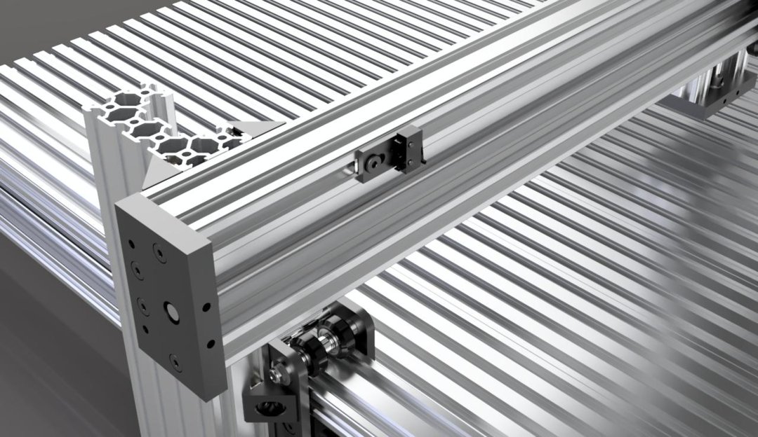
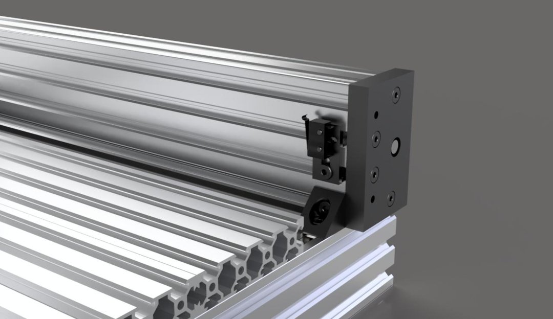
Use an M5x8mm screw through the larger hole on the limit switch plate to attach the assembly to the machine. When finished, there should be a switch for X-, X+, Y-, Y+, and Z+. The Z- will be handled in a different way later on, or, as a fail-safe, you can make a 6th limit switch assembly for Z-. It will be clear where this limit switch would go if you decide to use one.
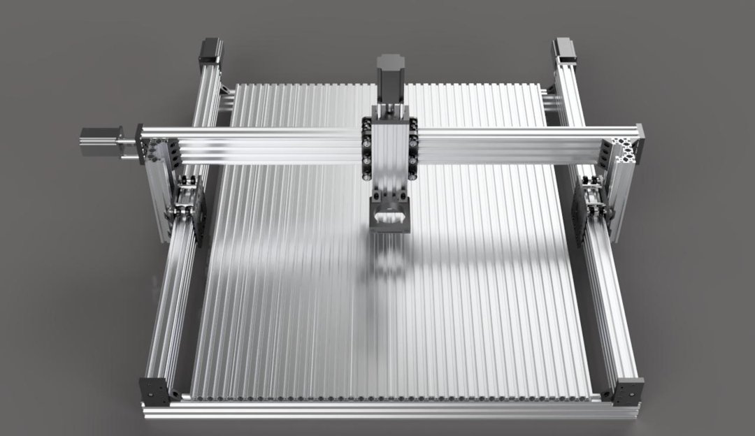
Congratulations! Your machine is now assembled. All you have left to do is wire everything up. I will be adding those steps once I have done them to my own machine.
The Beeline CNC
Build in 'Cartesian Style CNC' published by blterry1, Feb 28, 2018.
Here are the instructions to build the Beeline custom CNC router table.
-
-
Build Author blterry1, Find all builds by blterry1
-
- Loading...
-
Build Details
- Build License:
-
- CC - Attribution NonCommercial - Share Alike - CC BY NC SA
Reason for this Build
I built this machine to start a business with my wife. We will be making custom wooden signs as well as other custom wood decorative and useful objects. I would rather let a computer handle the cuts because I am apparently incapable of free-handing a straight line.Inspired by
This build is heavily influenced by ahayden's design(https://openbuilds.com/builds/c-beam-prefab-untitled.3986/). There are some differences, but I mainly remade their design because they did not include any parts list or build files that I could find. Most of the sub-assemblies are based off of OpenBuilds' own C-Beam machines though(https://openbuilds.com/builds/c-beam-machine-xlarge.3675/). They have developed a fantastic actuator/gantry system. I am extremely grateful to these two builds. Without them, this build would not have been possible. Huge thanks to OpenBuilds and to ahayden! -
Parts list
-
Attached Files:
-


