Welcome to Our Community

Some features disabled for guests. Register Today.

Sphinx Z-axis upgrade

Discussion in 'CNC Mills/Routers' started by Andreas Bockert, Aug 21, 2018.
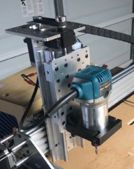
  1. Andreas Bockert

    Andreas Bockert Well-Known
    Builder

    Joined:
    Oct 1, 2017
    Messages:
    142
    Likes Received:
    78
    Andreas Bockert published a new build:

    Read more about this build...
     
  2. CNCMD

    CNCMD Journeyman
    Builder

    Joined:
    Jul 29, 2017
    Messages:
    148
    Likes Received:
    114
    Check out my build, I build a Z Axis just as you are describing, might help you out some.

    HD CNC
     
  3. Andreas Bockert

    Andreas Bockert Well-Known
    Builder

    Joined:
    Oct 1, 2017
    Messages:
    142
    Likes Received:
    78
    That looks nice! I’m going a bit less beefy. 12mm round rails and 12mm ball screw. Unless I start upgrading more things then this should be the stiffest part of my machine by far.

    Your design looks very similar to mine. Im planning to go with a belt drive like the Sphinx.

    I’m also planning to simply thread the back plate and attach the rails to it directly. My rails are closer in height to the ballscrew.

    A few questions:

    Does the bottom plate in the z-beam fill any purpose other than looking awesome?
    Are you happy with 1/4 inch back plate? I’m concerned that it won’t be enough meat for the threads.
    Did you add the mount holes for limit sensor after the initial cut?

    I’ll study your build closer when I have more time.
     
  4. CNCMD

    CNCMD Journeyman
    Builder

    Joined:
    Jul 29, 2017
    Messages:
    148
    Likes Received:
    114
    I don't know what you mean by Belt drive. The Sphinx is leadscrew driven.

    -The bottom plate doesn't really serve any purpose other than looks.
    -1/4" is plenty good for the back plate. You need to remember that weight is a concern. Depending on your span of your X axis, and the spindle choice, you could be talking serious weight.
    - The holes were in the plate when initially machined. I have since abandoned the hall effect limit switches. The product is fine, but requires you to orientate the sensor so it must sit in a real specific way. I am using standard roller limit switches, but honestly this is one area I would like to improve upon, given that mounting is not a huge undertaking.

    More pics of my machine can be found at: CNC Studio (@cncmaryland) • Instagram photos and videos
     
    GrayUK likes this.
  5. Andreas Bockert

    Andreas Bockert Well-Known
    Builder

    Joined:
    Oct 1, 2017
    Messages:
    142
    Likes Received:
    78
    Thank you for the answers.

    What I mean is the Sphinx has two pulleys you couple the stepper to the lead screw. I’m plan on to stick with this at the moment.

    The limit switch mounting is something I still haven’t designed. Perhaps I’ll simply add a whole bunch of threaded holes for future expansions. :p

     
  6. CNCMD

    CNCMD Journeyman
    Builder

    Joined:
    Jul 29, 2017
    Messages:
    148
    Likes Received:
    114
    Ahhh, gear reduction drive. I just not a fan of that, to me the more parts, the more chance of something going bad. To each their own. Good luck with your build!
     
    Peter Van Der Walt likes this.
  7. HPB

    HPB Well-Known
    Builder

    Joined:
    Nov 28, 2015
    Messages:
    80
    Likes Received:
    52
    Came across this when I was looking for Z-assemblies for my machine. Right now its somewhat like the OX and the Workbee but my machine is made from Plywood plates and its just not stiff enough. Maybe I'll replace the linear bearings with slides. I'm having trouble with chatter too on my Y-axis while cutting in the Y- direction. I'll try the trochoidal milling path.
     
  8. SCYBUCK

    SCYBUCK New
    Builder

    Joined:
    Sep 11, 2017
    Messages:
    36
    Likes Received:
    13
    Andreas, you stated that you used a regular 3/4" wood router bit to face the aluminum. Please tell us the make and model number of that bit. I just started a build page here on Openbuilds now that I am starting to cut aluminum. BTW, great face job with that bit!
     
  9. Techvette

    Techvette New
    Builder

    Joined:
    Oct 1, 2017
    Messages:
    63
    Likes Received:
    23
    Very cool!

    It looks like your old Z needed to be trammed a bit. That could also contribute to broken bits if you're cutting a slot that's deep enough. How are you handling chip evacuation?
     
  10. Andreas Bockert

    Andreas Bockert Well-Known
    Builder

    Joined:
    Oct 1, 2017
    Messages:
    142
    Likes Received:
    78
    It is a Bosch bit but I think that any 3/4 carbide bit should work as long as you’re taking a shallow pass.

    And indeed, the z axis needed tramming. Did that and the last plate I surfaced this way turned out well.
     
  11. Andreas Bockert

    Andreas Bockert Well-Known
    Builder

    Joined:
    Oct 1, 2017
    Messages:
    142
    Likes Received:
    78
    Oops, mixed up the responses. After som troubleshooting a figured out that I had backlash in both x and z. No good. I also ran it to aggressively to begin with.

    Regarding chip evacuation I moustly cut outside profiles and didn’t do any slotting.

    One plate that had a more complex design I cut by cutting a 3/8-ish slot instead of 1/4 using adaptive clearing.

    The few pockets that I had were shallow so chip clearance wasn't an issue.
     
    #11 Andreas Bockert, Oct 16, 2018
    Last edited: Oct 16, 2018
  12. Rick 2.0

    Rick 2.0 OpenBuilds Team
    Staff Member Moderator Builder Resident Builder

    Joined:
    Dec 20, 2013
    Messages:
    2,852
    Likes Received:
    1,524
    Magnate make some decent bits for this. I have the 1-1/4" (2714) and it leaves a beautiful surface. The key is barely shaving the top off.
     
  13. Techvette

    Techvette New
    Builder

    Joined:
    Oct 1, 2017
    Messages:
    63
    Likes Received:
    23
    I've also had success using typical wood bits for some aluminum tasks, but I'd be prepared to throw the bit away when you're done unless your F&S are just right. I made the stupid mistake of using a 3/4" straight bit to surface some 1/2" AL, then trying to use it on an irreplaceable piece of quarter-sawn red oak the following week. Fortunately, I stopped the job quickly. :|

    On a slightly-related note, I encountered a couple of staples embedded in the middle of my Home Depot 3/4" MDF spoilboard while resurfacing. There goes a $35 surfacing bit.
     
  14. Techvette

    Techvette New
    Builder

    Joined:
    Oct 1, 2017
    Messages:
    63
    Likes Received:
    23
    So, rather than cutting a "slot" that's the width of the bit, leading to chip cloggage (not a real word), you're cutting it 50% wider? That makes sense. I wish EstlCAM provided an easy way to do that. Guess it's back to fighting with Fusion.
     
  15. Andreas Bockert

    Andreas Bockert Well-Known
    Builder

    Joined:
    Oct 1, 2017
    Messages:
    142
    Likes Received:
    78
    Once you make the investment of learning fusion you will never look back. Having integrated CAD and CAM is a killer combo. The CAM is also very powerful. Also, I just love parametric CAD.
     
  16. HPB

    HPB Well-Known
    Builder

    Joined:
    Nov 28, 2015
    Messages:
    80
    Likes Received:
    52
    You don't need to 'fight' with Fusion's CAM :) Their own documentation and videos are very helpful and very informative. I spent a total of 2 days looking over the options, simulating it and it was surprisingly easy. There are a few nuances that you'll come across such as chatter with slots on less rigid machines. At that point you know what is happening and you have a specific topic you can seek advice on. At least thats what I did.

    I used estlcam recently and cutting slots with it is very tiresome. For some reason, it does the trochoidal path and then reverses back to the start point doing another trochoidal path (essentially cutting air). This was very irksome since it doubled the machining time. Its great for cutting outlines from stock material and where you don't want to reduce the entire piece of stock to chips.
     
  17. 3DStyle

    3DStyle New
    Builder

    Joined:
    Aug 26, 2018
    Messages:
    6
    Likes Received:
    1
    Your project seems interesting, any chance to get the files for cutting the aluminium? I would like to try it too :)
     

Share This Page

  1. This site uses cookies to help personalise content, tailor your experience and to keep you logged in if you register.
    By continuing to use this site, you are consenting to our use of cookies.
    Dismiss Notice