
Heavy-Duty Build 1000 x 500 consisting of the following:
Plates
Custom Made Plates:
Y Plates - .5" Cast Aluminum
X & Z Plates - .25" Cast Aluminum
Extrusion
V-Slot - 20x80 for Y Axis
V-Slot - 20x20 for Z Axis
C-Beam 20x80 for X Axis
Linear Rails
HIWIN brand
2x HGR20-L500mm Linear rail
4x HGH20CA Linear carriage
2x HGR15-L1000mm Linear rail
2x HGR15-L300mm Linear rail
8x HGH15CA Linear carriage
Ballscrews
1x Rolled1605-L315mm+1pcs single flange ballnut with end machining (Threaded length = 250mm)
2x Rolled1605-L565mm+1pcs single flange ballnut with end machining (Threaded length = 500mm)
1x Rolled1605-L1065mm+1pcs single flange ballnut with end machining (Threaded length = 1000mm)
3x FK12+3pcs FF12 support
1x BK12+1pcs BF12 support
4x D25-L30-10*6.35mm Flexible coupler
4x Nut housing
Other Items
Creltek Hall Effect Sensors (Limit Switches)
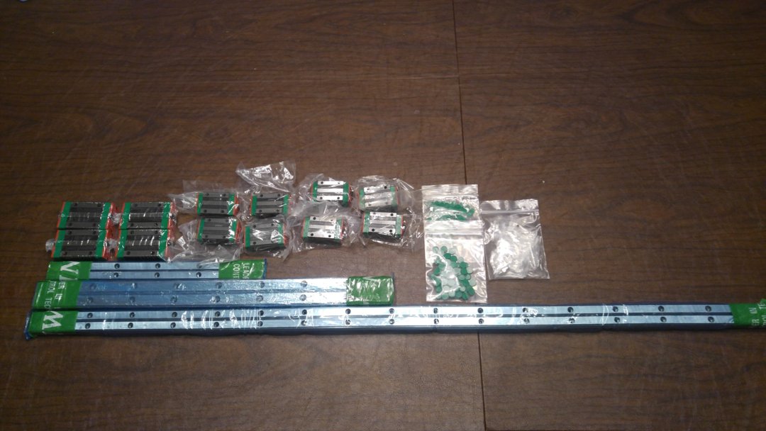
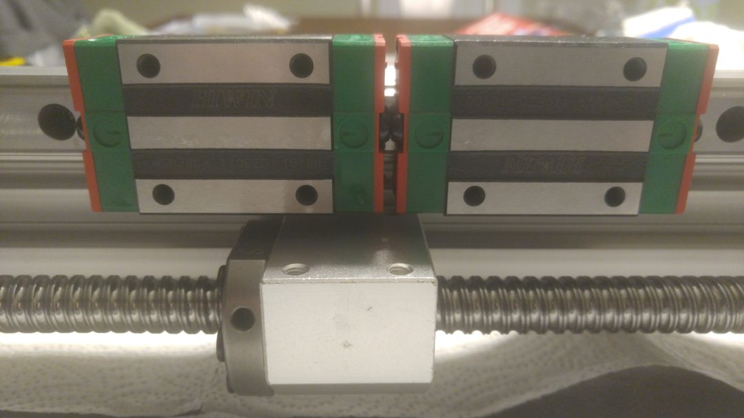
Linear Rails and Carriage Blocks
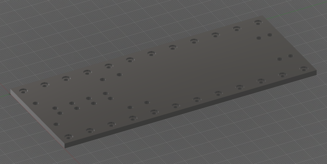
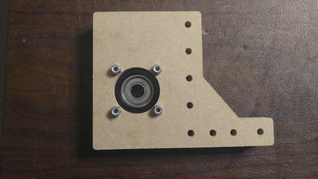
Z Axis Base Plate Prototype
Z Axis - Base, Top and Bottom Plates
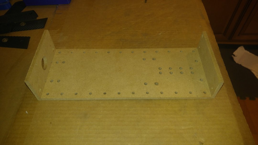
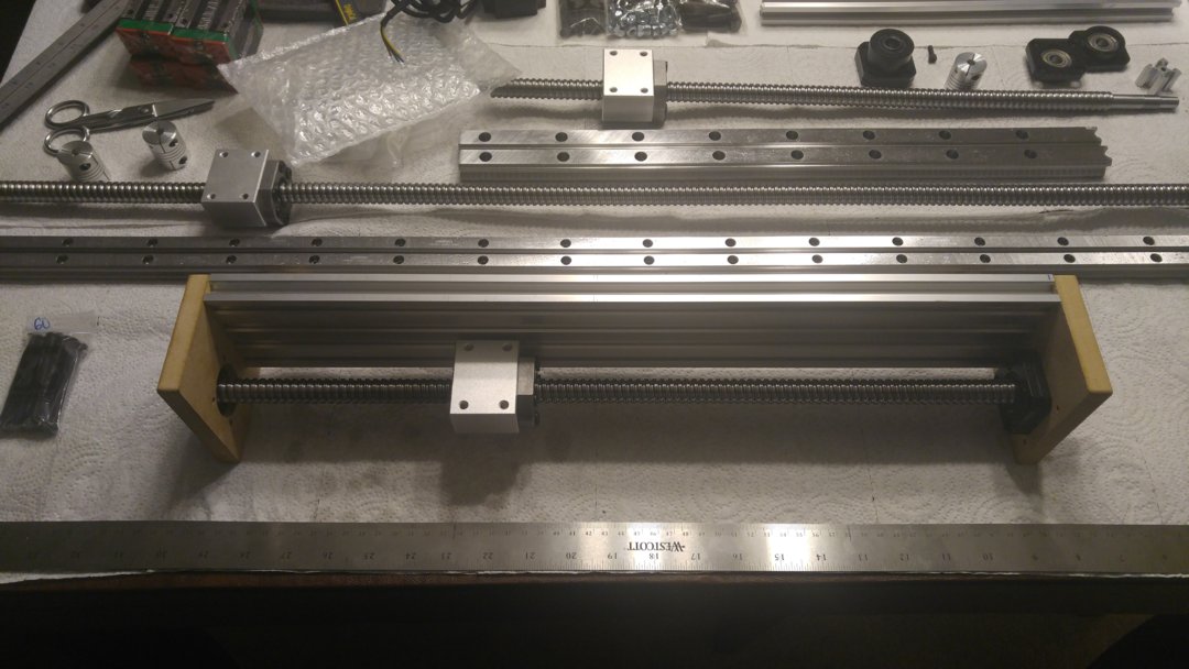
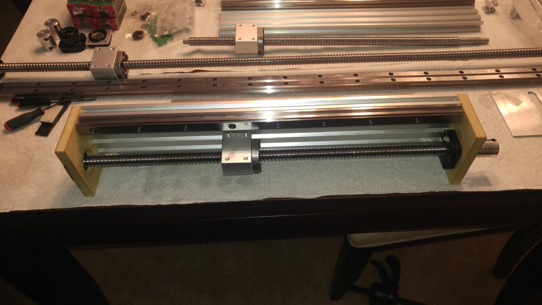
Test fit of linear rails. There will be 20x20 extrusion under these. This is just to ensure the rails will fit between the end plates.
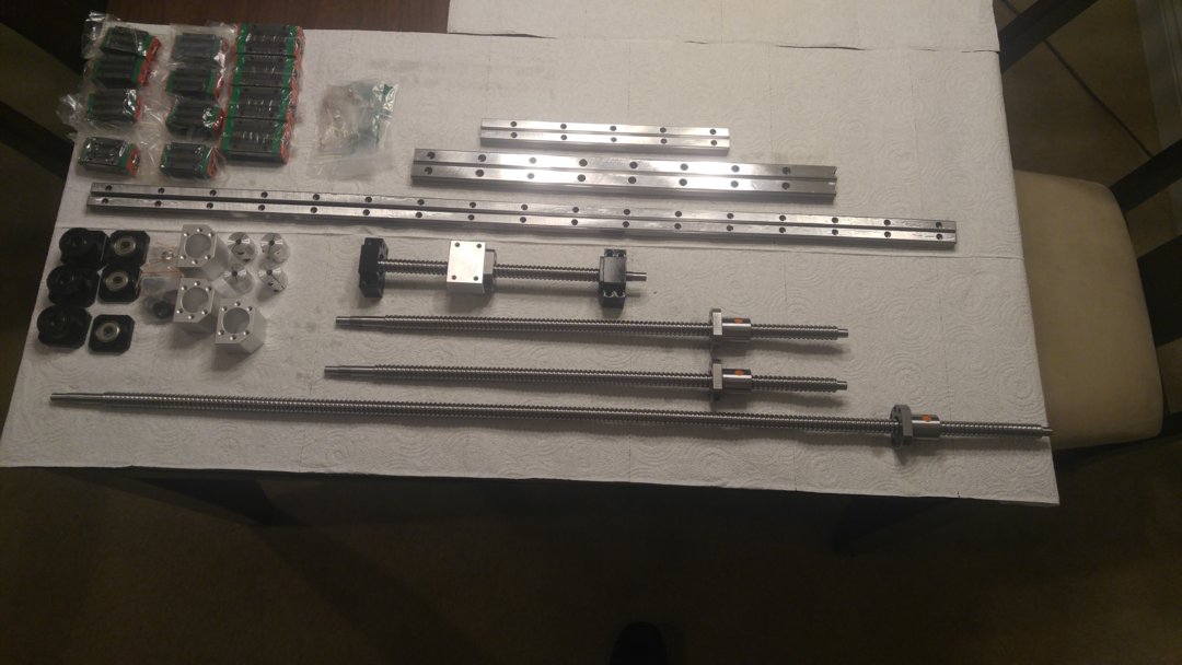
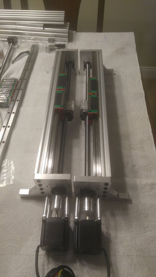
Ballscrews, End Supports, Nut Housings and Couplers have arrived!
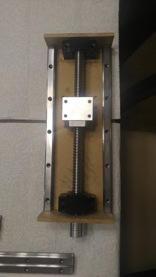
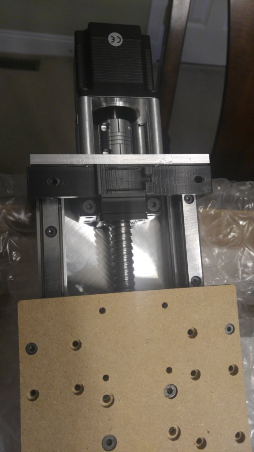
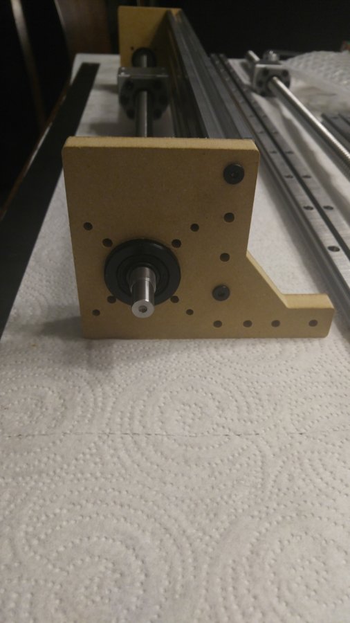
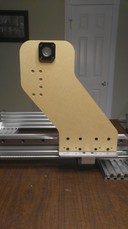
Initial Mock-up of Z Axis. Openbuild Parts should be here shortly for the remainder of parts!
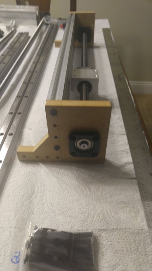
Z Axis plates cut and test fit. Just waiting on 20x20 extrusion and this can be fully built. The spindle mount plate will follow.

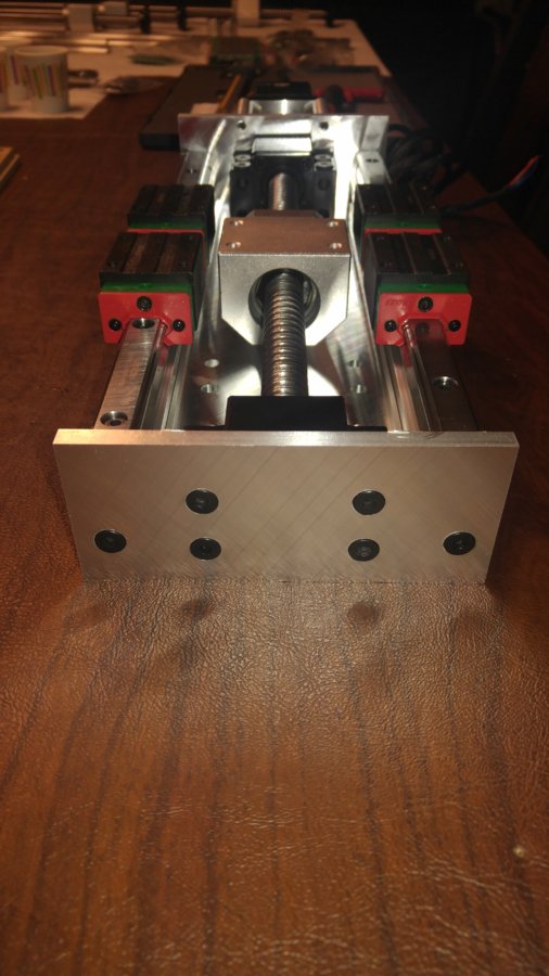
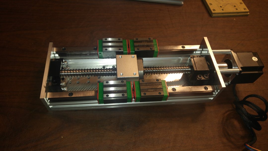
Completed Z Axis.
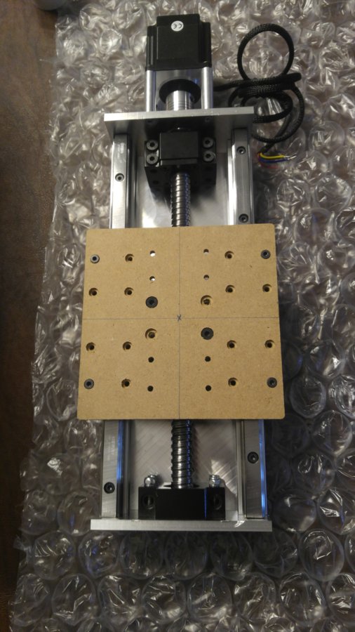
Mock Z Gantry Plate.
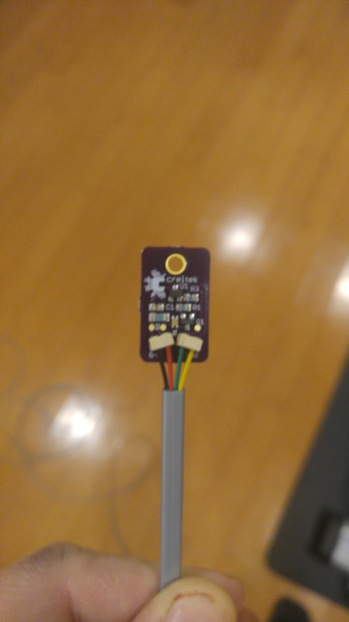
Creltek Hall Effect Limit Sensor
Mounting Bracket for the Creltek Sensor. These were designed by Michael M. on the forums. He put me on to these and they are going to be great.
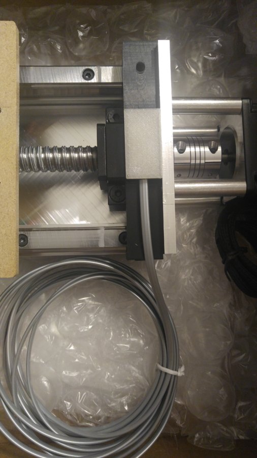
Here is the sensor wired up, in the bracket, with the transparent cover installed.
The sensor has LED's that let you know when they are tripped.
Z Gantry Plate
Happy to say, Completed Z Axis. All ready to go. I am going to swap over my Openbuilds Mounts and Water Cooled Spindle when everything else gets done. This part is fully function tested, along with the Hall Effect Limit Switch.
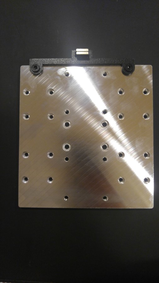
Backside of the X Gantry Plate
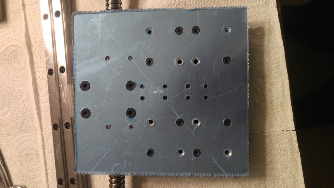
Front Side. Still need to tap some holes before I can remove the film.
Another view of the rear.

Fully Completed X plate, Holes fully tapped. This is ready to go!
At this point, Z and X are completed.
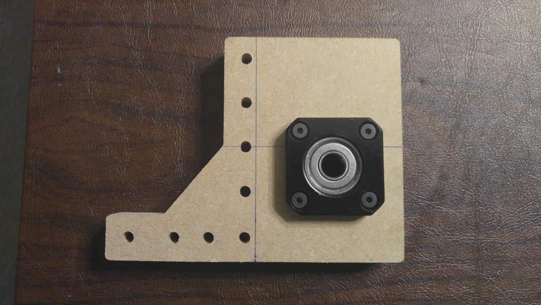
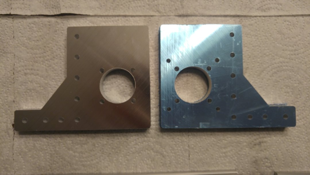
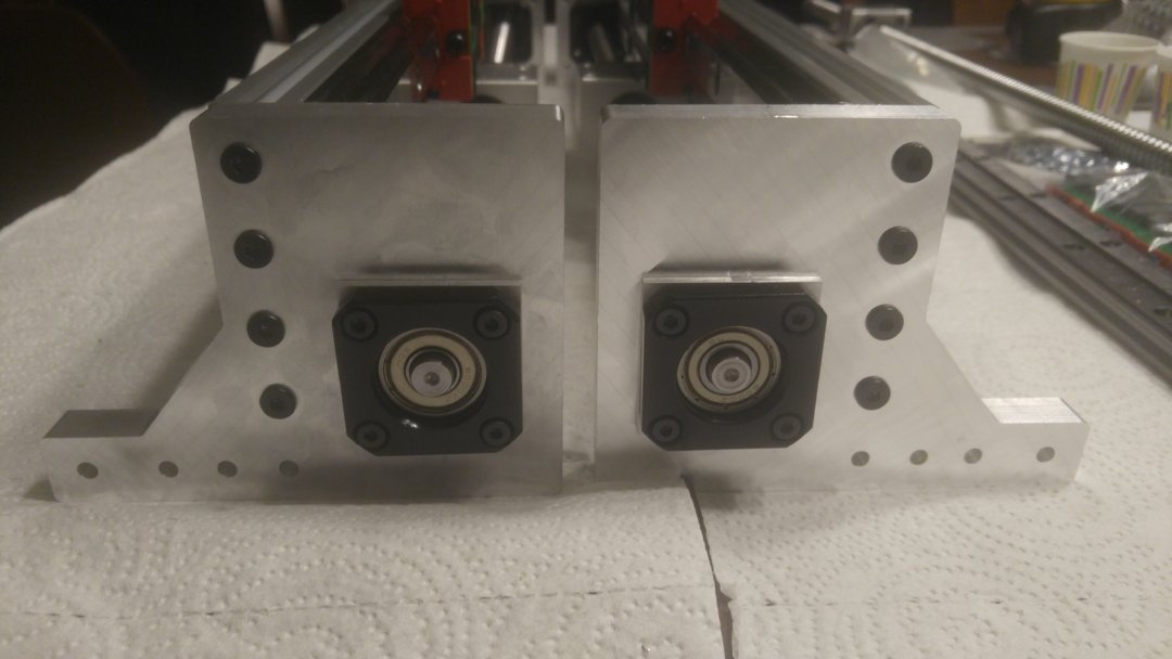
Y Plate for Bearing Support - Floated Side. The beauty of these plates is they are reversible, meaning, you can use on the left and right side.
Mock up of the Y Axis Bearing Plates. This looks like a workable setup. The biggest obstacle in this entire build is not changing the footprint of the machine. I am going to build the base soon, but want to use the 1/2" cast plate that I have currently for a base plate.
Any minor gaps that exist are going to be dealt with by cutting shim plates that will fill the gap and look the part.
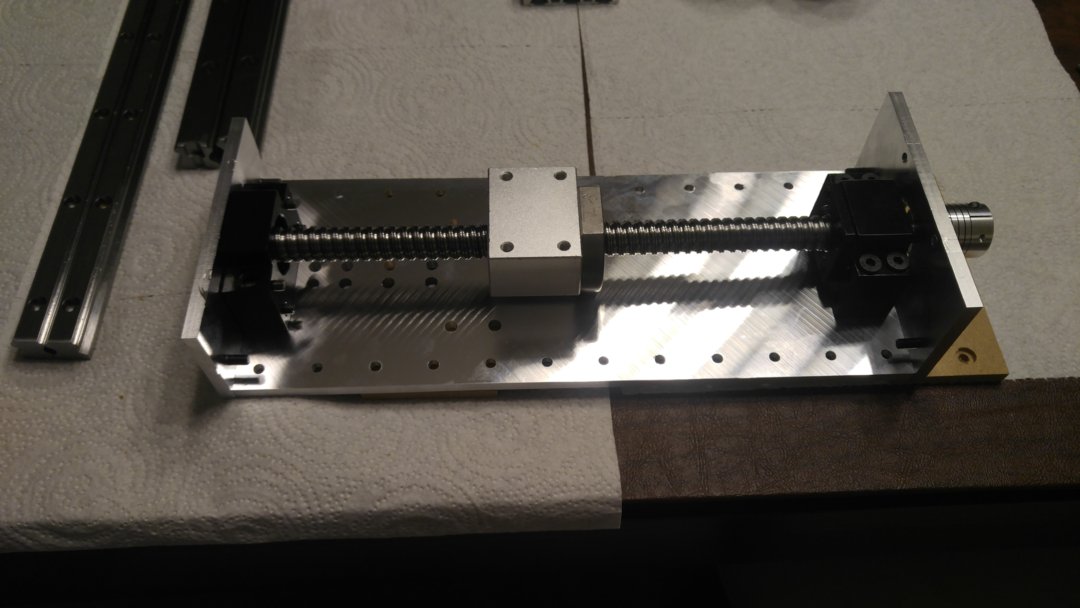
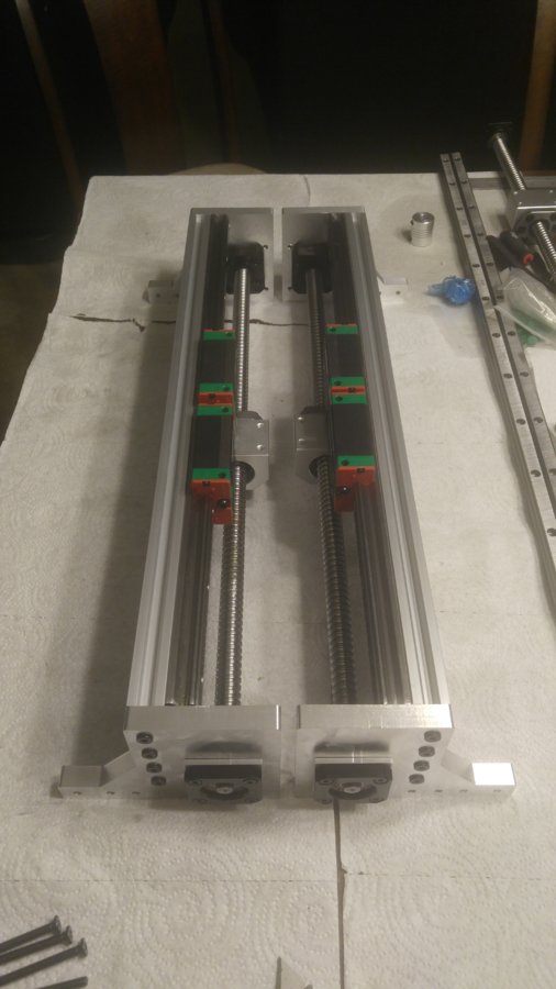
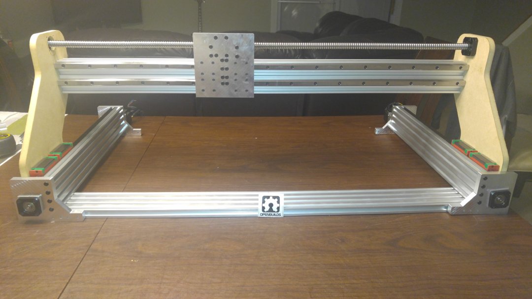
500mm Y axis extrusions, cut, tapped and a 500mm Hiwin 20mm linear rail attached.
Y axis mock up with cut extrusion and rail.
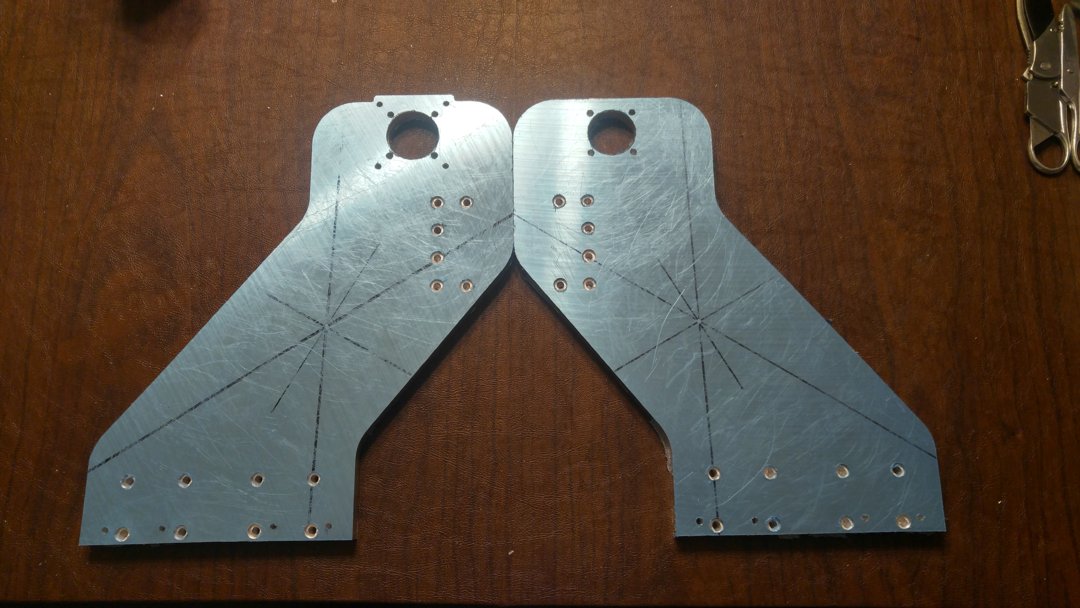
Next step is to fit a limit switch on the Y axis, and cut the plates. Hope to have both Y axis front and rear bearing supports cut by next week. These plates will be cut from 1/2" cast aluminum.
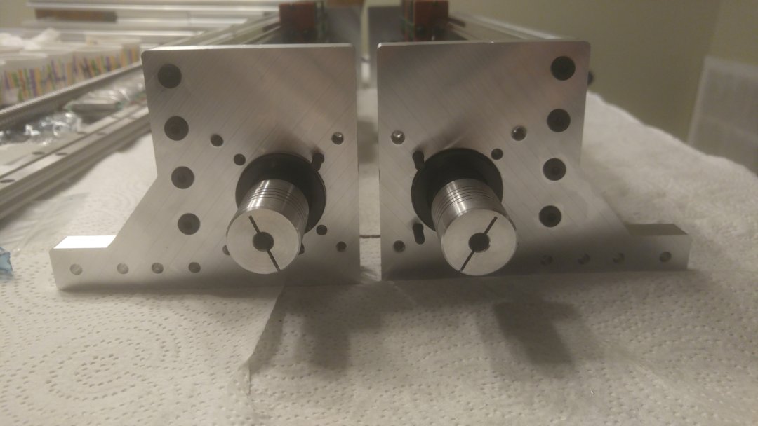
Just finished the first set!
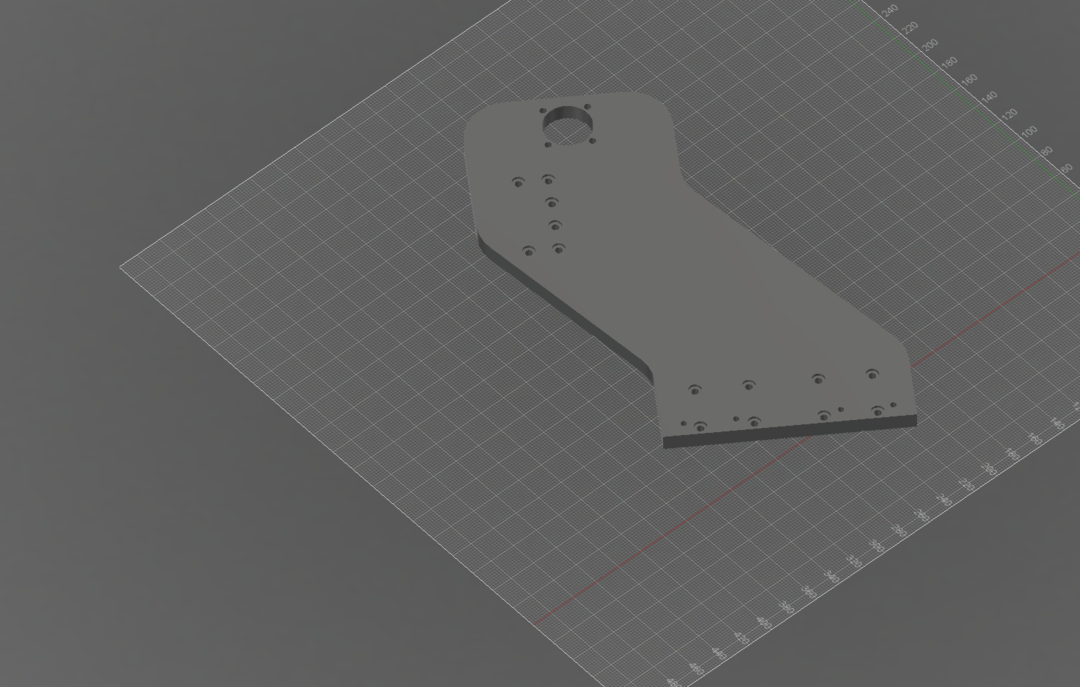
After that, I need to design that plate that connects the Y ballscrew nut housings to the Y gantry plate, and then finally the Y gantry plates. Edit: plate has been designed.
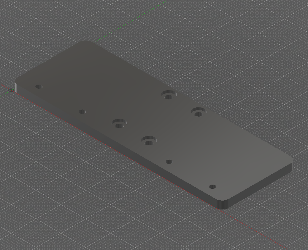
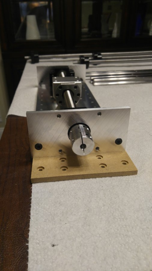
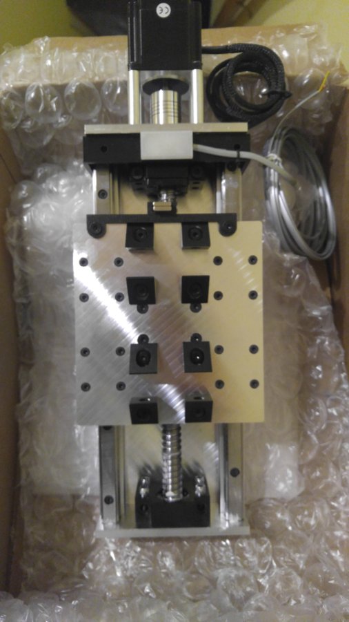
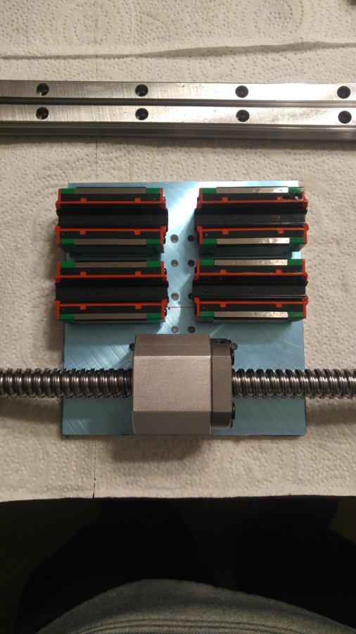
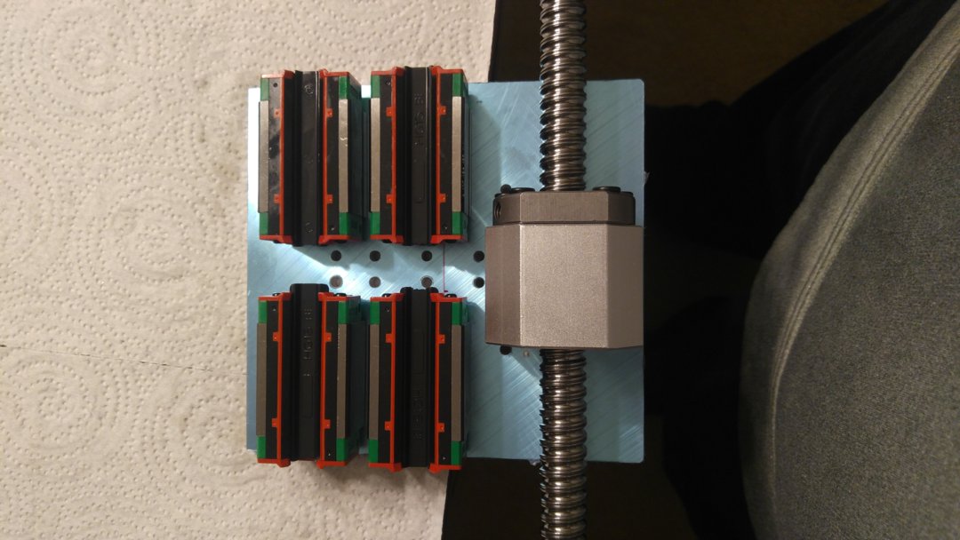
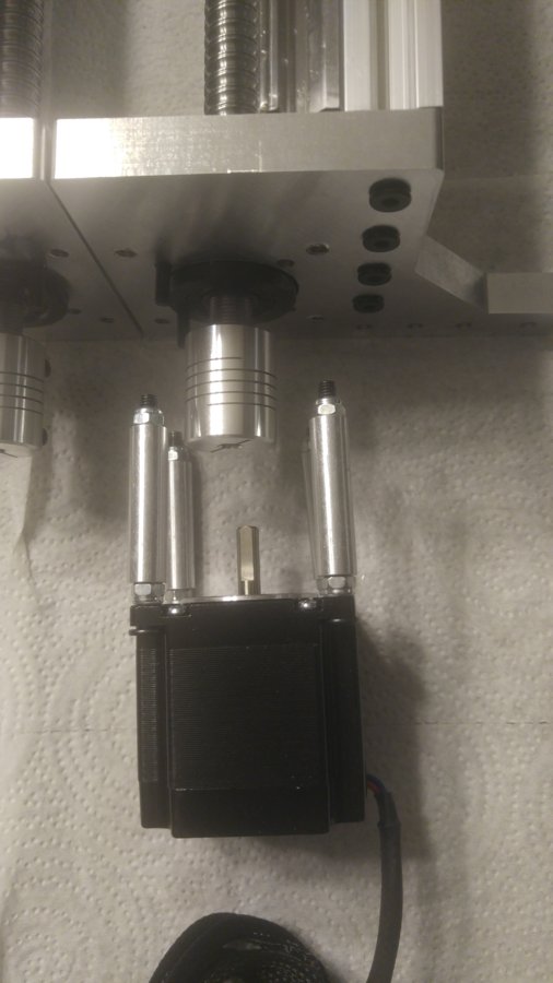
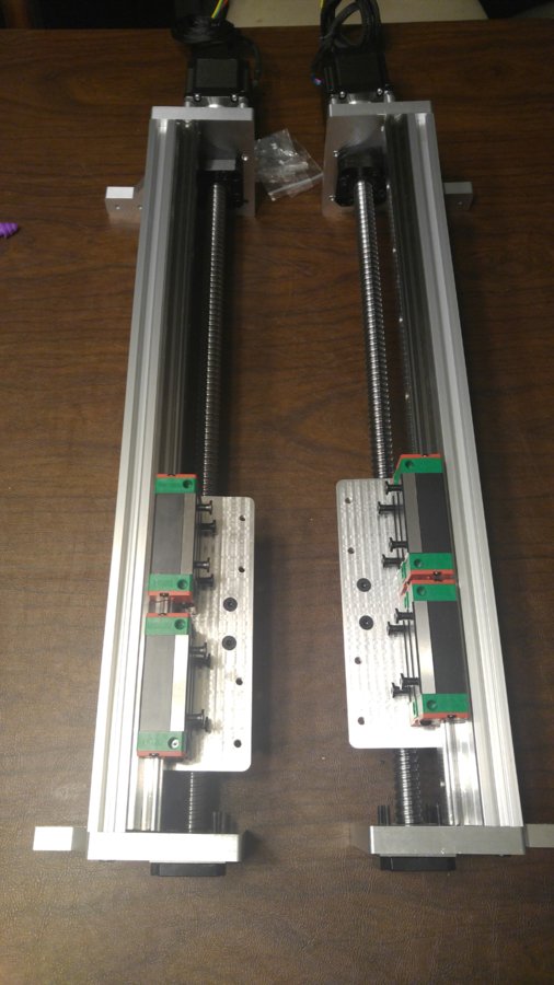
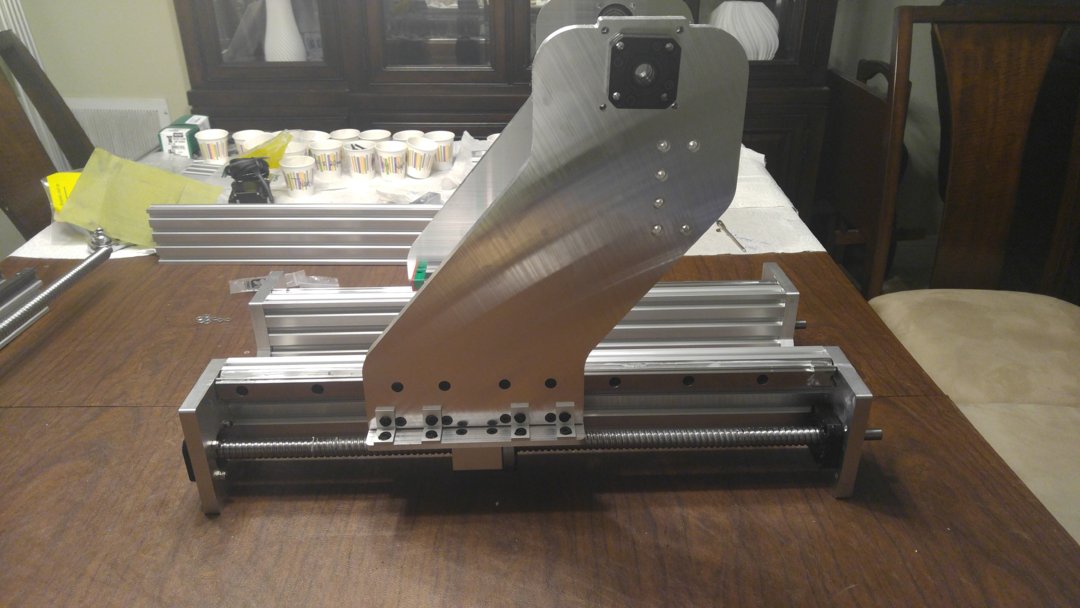
Here are the almost completed Y Axis'. Missing a few bolts but they are ordered. Motor are also ready, using "custom" lol motor spacers. Next will be to machine the image above, which will ride on the ballscrew housing. Also working on the Y Axis Limit Switch. All coming soon.

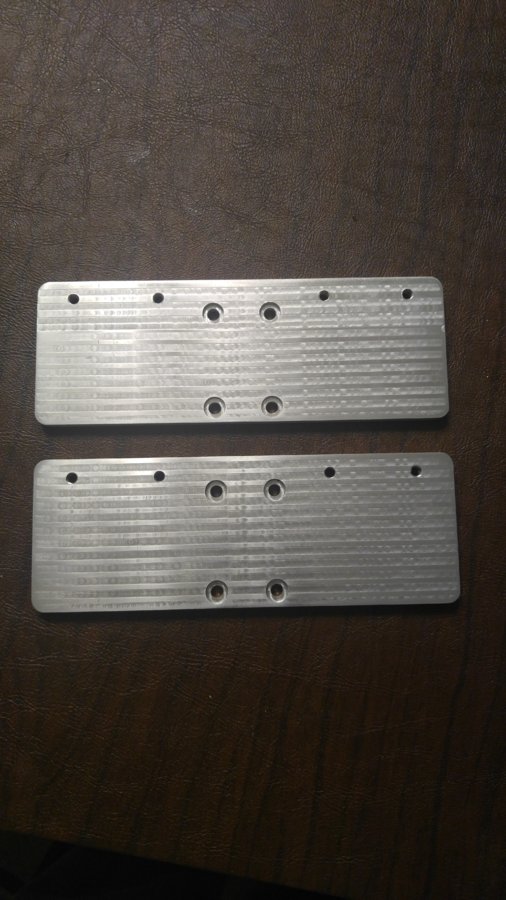
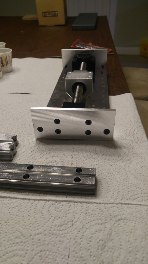
The plates that connect the ballscrews housings to the Y Gantry Plate. Will be using L Brackets to make the connection.
Below is a mock up of the Y Gantry Plates. If my calculations are correct the center of the spindle should be exactly at the center to the bearing blocks. I will continue to make revisions and check my calculations. This is the floated bearing side, which on my machine is on the left side of the machine.
Any comments on this plate are welcome.
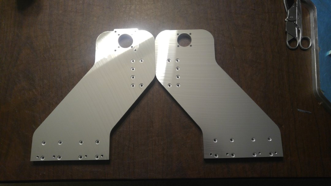
Got both sides cut, minimal kinks to workout. Hope to cut the plates in the next few days.
At that point I need to make sure that everything that is needed is prepared before I dissemble the old machine.
Side of Gantry
Full Gantry with frame!
Ok, had to work on my hold down method, pickup up some Legacy lo pro clamps.
Got both Y Gantry plates cut, tapped, fitted and tested. Still need a few minor adjustments to the movement.
Nearing completion. Next is to mount to frame and fit the x axis.
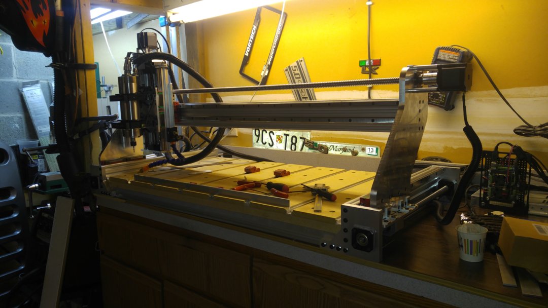
Happy to report, the machine is now completed, and in the testing/refinement section of the build. All that is left is mounting of limit switches, and tramming of the Z axis.

HD CNC
Build in 'Cartesian Style CNC' published by CNCMD, Oct 24, 2018.
Heavy Duty build with 1605 Ballscrew and Linear Rail
-
-
Build Author CNCMD, Find all builds by CNCMD
-
- Loading...
-
Build Details
- Build License:
-
- CC - Attribution - CC BY
