Some philosophy about the current build.
Square rail vs round rail
- Sphinx compatible - I want to be able to upgrade one piece at a time.
- Affordable - Since I'm doing this for my entertainment I want to keep the costs down.
- Easy to mill - I've managed to cut some aluminum with my CNC but I'm still very green. Hence, I want to avoid milling anything that requires tight tolerances. The plan is to mostly spot holes and drill them on the drill press.
I went with the round rail both since it was cheaper and it seemed more tolerant to misalignment.
8/20:
I pulled the trigger on some parts, early Christmas!
The plan is to mill the front plate, back plate and some kind of motor bracket. I think 0.25" aluminum should be stiff enough, especially since the rails will be adding rigidity to the construction.
Most of the critical measurements are holes that I plan to simply spot on the CNC and finish on the drill press.
8/21:
The ball screw arrived today. It seemed to solid. No obvious wobble or running rough. The bearing blocks slid on easily which can be a problem from what I've heard. I've also been working on the CAD side of things. The plan is to create a prototype out of wood before cutting the real thing.
8/23:
Still waiting for the rails. Some final touches to the CAD. It's really powerful to be able to import openbuild-palts into Fusion360 to verify that everything aligns properly!
8/30:
Made a prototype back plate out of plywood to verify hole placements. It seemed to align well. One unusual choice in my design is that I’m leaving the bottom of the ball screw floating. That way I could achieve more travel and make the design a bit narrower.
According to my CAD model I should get about 15cm (6”) of travel. That’s 5 (2”) more then the current setup.
9/6:
I made a plywood front plate and tested the fit. It seems like it should work. One thing that I need to figure out is the the thickness of the shim that’s needed beneath the screw mounting block.
Created a plywood plate for the motor mount. I found the first gotcha, it needed to be wider to avoid the angle-irons catching the screws.
9/8:
Started to prepare for cutting the aluminium. I created an extra wastebord on top of the the regular one and trammed it. (I haven't gotten around to tramming my real wasteboard yet).
I also have some experiments to run before cutting the real deal.
1. Testing spot drilling in aluminum.
2. Cut tight pockets in aluminum (1/8 end mill)
3. Try proper contouring.
9/9:
Tested cutting some small pockets in aluminum. I'm able to go quite aggressively with the CNC. Some settings for interested persons.
Fusion 360 with 1/8" endmill:
1. Adaptive clearing: 25000 RPM, 2500 mm/min (about 100IPM) and 0.5mm optimal load, depth of cut of max 3.5mm (0.14"). Stock to leave 0.2mm
2. 2D Contour: 25000 RPM, 2500 mm/min. Roughing pas that leaves 0.2. Depth of cut 2mm.
I have gone full depth of cut of 0.25" in the past but that was an open profile type cut. With this relatively tight pocket I'm concerned with chip evacuation so I figured going two passes wouldn't hurt. Besides, the economical consequences of tool wear on my cheapo 1/8 end mill is negligible.
The 2D Contour is all about cleaning up deflection. After the adaptive clearing there is certainly more than 0.2 mm left due to tool/machine deflection. Hence the need for both a roughing and a finishing pass.
I also spent some time testing my 0.25" 90" spot drill. The results were not that encouraging. There was significant flex when drilling. Not quite sure what settings to use. I tried 15000rpm and various feeds but all seemed to flex. Suggestions welcome!
9/17
I've mostly been doing testing to determine speed/feed to use in milling. For me, I've had the best luck with pretty aggressive settings. I.e. high feedrate and shallow width of cut. One test cut last night cam out over-sized by about 0.25 (both width hand depth of my piece was oversized by 0.25mm). I figured it was due to machine deflection. But still, it wasn't adding up since I was taking a really light finishing pass (0.1mm).
Then, I took the caliper to the endmill and it measured 3.05mm (instead of 3.175) a difference of 0.125 mm. This at least goes part of the way to explain the discrepancy. Moral of the story, don't use worn out endmills if you care about dimensions.
One successful test was to face of the aluminum with a regular 3/4" wood router bit. Shaving of 0.1mm and using 50% stopover resulted in pretty nice finish.
Sorry for the poor quality video.
9/21
I've mostly been experimenting with cutting outside profiles. Honestly it's been going pretty badly and I get terrible chatter no matter what I try. The weird (well, perhaps not weird, but annoying) thing is that I only get chatter along Y, and especially when cutting +Y. I've tried different RPMS, different speeds and different endmills. I've busted a few of the 1/8" by now. Good thing they're cheap.
I have a 3 flute 1/4" endmill that I'll give a try. If that doesn't work I'll try to force it to use a trochoidal toolpath. This will be slower but at least it will prevent it building up a significant resonance.
The only other option I see is to REALLY baby it, i.e. 0.5mm DOC....
John Saunders shows how to do it (At about 3:20 in)
9/23:
I did some more experiments, using the 3 flute endmill seemed to cut down on the chatter. In the end, these are the settings I settled on:
1/4", 3fl endmill, 10K RPM, Feed: 2100 mm/s (84 IPM), WOC 0.5mm (0.02"), DOC 3.5mm (0.14")
If it wasn't for the nasty chatter I could push it harder. Probably go the full 1/4" DOC.
9/26:
Started cutting the first plate, the top motor mount. This is very similar to the reduction/stand off plate (https://openbuildspartstore.com/reduction-stand-off-plate/)
Got half way through the milling and only snapped one endmill in the process. With any luck I can finish the milling tomorrow.

9/27:
Began milling the outline but hit a couple of problems. First attempt, I messed up the CAM, causing the end-mill to plunge into the edge of the material. Making a nice, kaalonk sound.. Brr, it seemd to survive. Second attempt, update the CAM and go. I didn't re-zero after the first attempt causing ot to cut much deeper then anticipated. Redo, rezero, restart... Forth attempt, it was chugging along but after a while it made another nasty kaalooonk sound and the end-mill embedded itself into the wasteboard. Duh! Tighten the collet dude! Fifth start, it was chugging along and passed the critical spot. However, I realized that it would take too long to complete so I stopped the run for now. I'll revisit it later....
9/28:
Success! My latest CAM tweaks seem to have done the trick. Due to my earlier failures the outline and the holes on the part doesn't align perfectly. However, due to luck, erm, I mean, my foresight this shouldn't be a problem since 100% alignment isn't critical on this part.
1 down, 4 to go...


10/4:
After some struggles I managed to mill the back plate. The z collar knocked loose a few times for me. I have to tighten it up before I start with the next plate.
I also drilled and tapped all the holes on the back plate. About 40 or so. Only one turned out to be bad so that’s a success.
Next up is the front plate that attaches the router and the ball screw nut.

10/12:
I finally cut the front plate and assembled the Z axis. I have one more plate to cut. (Bottom plate, just as a minor protection against chips). It took some shimming but it's coming to gether nicely. At the moment it weights in at 3.4kg (7.5lbs). Not a lightweight. It certainly will be the most rigid part of my machine.
The front plate milling was an adventure. First, I tried Adaptive clearing, 1.5 mm DOC, 0.5 mm Optimal load, 2400 mm/min (95IPM) . However, this felt like pushing it for sure. Lots of chatter and some stabs. A more successful recepie was to run 6mm DOC, 0.15mm Optimal load and 4000 mm/min (160 IPM). It should result in similar removal rates.
I'm waiting for some more m5 screws and then I need to mount it to the machine.
10/15:
There is light at the end of the tunnel! I got the beast mounted on the Sphinx. There were not to many hickups. The holes lined up fairly well and things seemed nice and square.

This thing is huge. The regular 300mm Z axis was 1.4 kg vs 3.4kg for the new one. In hindsight, I should have made it a bit shorter to save on weight. Here they are side by side.

One design feature I'm really happy with is that the mount is very close to the bottom edge and that the bottom edge actually extends past the end of the rails. This allows for some very short end-mills.

10/17:
It's done!
Some final thoughts...
Overall, the process was ok.
Cutting aluminum is a big difference to cutting wood or plastic. The range of acceptable parameter are much much smaller.
I should have gone a bit smaller. I don't really need the massive Z-range and that's a lot of extra weight.
Perhaps I should have gone with a 3/8" front plate. Right now this has a bit of flex to it. I'm planning to double up the mounts and I think this will help with the flex. Otherwise, it would be fairly easy to recut the front plate.
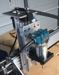
Sphinx Z-axis upgrade
Build in 'Cartesian Style CNC' published by Andreas Bockert, Oct 18, 2018.
Upgraded Z-axis for Sphinx-style CNC using ball screws and linear rails.
-
-
Build Author Andreas Bockert, Find all builds by Andreas Bockert
-
- Loading...
-
Build Details
- Build License:
-
- CC - Attribution - CC BY
Reason for this Build
I wasn't 100% happy with the rigidity of the Z-axis of my Sphinx so I decided to upgrade it. (Mostly because it's fun ;-)) -
Parts list
Qty Part Name Part Link Comments 2 250mm linear rail + blocks https://www.ebay.com/itm/2pcs-SBR12-L300-1500mm-Linear-Ra... Link 1 1204 Ball screw + blocks http://a.co/buU6C2s Link 2 0.25x5x14 Aluminum flat bar https://ebay.us/8tWJuY Link 0 Link 0 Link


