Welcome to Our Community

Some features disabled for guests. Register Today.

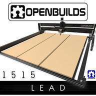
OpenBuilds LEAD CNC Machine 1515 (60" x 60")

Discussion in 'CNC Mills/Routers' started by OpenBuilds, Sep 29, 2020.

  1. OpenBuilds

    OpenBuilds Well-Known
    Staff Member Moderator Builder Resident Builder

    Joined:
    Sep 23, 2019
    Messages:
    22
    Likes Received:
    109
    OpenBuilds published a new build:

    Read more about this build...
     
  2. sharmstr

    sharmstr OpenBuilds Team
    Staff Member Moderator Builder Resident Builder

    Joined:
    Mar 23, 2018
    Messages:
    2,059
    Likes Received:
    1,448
    Congrats, Team!

    I'm sure this question will be coming so I'll be the first to ask. Have you tested with the High Z mod?
     
  3. Mark Carew

    Mark Carew OpenBuilds Team
    Staff Member Moderator Builder Resident Builder

    Joined:
    Jun 28, 2013
    Messages:
    2,757
    Likes Received:
    2,428
    Thanks @sharmstr welcome back! :)
    Yes adding bigger sides should not be a problem for this monster!
    We like to keep it low profile for the 99% use case of sheet materials so it's as rigid as possible.
     
    stuart wallace, Rick 2.0 and sharmstr like this.
  4. Rob Taylor

    Rob Taylor Master
    Builder

    Joined:
    Dec 15, 2013
    Messages:
    1,470
    Likes Received:
    748
    Nice! With so much machining space available, you should do a double-carriage Y version of the high-Z with A-frame extrusion, so that the extra leverage of the taller columns has opposing leverage on the actual rail holding it up. You'd lose an extra 6-10 inches of Y travel, but you'd have it in the X direction anyway.

    Depends how much deflection is within the high-Z beams' torsional deflection and how much is actually transferred to the Y-axis carriage wheels, but larger carriage footprint always = better.
     
    shane doyle and stuart wallace like this.
  5. Mark Carew

    Mark Carew OpenBuilds Team
    Staff Member Moderator Builder Resident Builder

    Joined:
    Jun 28, 2013
    Messages:
    2,757
    Likes Received:
    2,428
    That would be cool @Rob Taylor giving the best of both worlds!
    On the lower profile side of things we have so much strength you know we are working up cool mods for this one but that going to be a topic for another day ;)
     
  6. Rhett E

    Rhett E Well-Known
    Builder

    Joined:
    Aug 3, 2020
    Messages:
    113
    Likes Received:
    45
    I just placed my order, now I need to figure out where to put it.

    The lead 1010 has the option for nema 23 high torque motors but the 1515 doesn't. My caveman brain tells me bigger is better so why does the 1515 not have the option for the high torque motors? Also, the 1515 stays with 8mm screws. I know all of this has been rigorously tested but that doesn't seem very beefy for a near 5ft run.
     
    Miguel Viana, Mark Carew and Giarc like this.
  7. Giarc

    Giarc OpenBuilds Team
    Staff Member Moderator Builder Resident Builder

    Joined:
    Jan 24, 2015
    Messages:
    3,001
    Likes Received:
    1,675
    SOMETHING BIG IS COMING!!

    This is awesome! I will assume that since I guessed right, I won one. You already have my shipping address. ;)
     
    Mark Carew and sharmstr like this.
  8. Metalguru

    Metalguru Veteran
    Builder

    Joined:
    Dec 29, 2015
    Messages:
    752
    Likes Received:
    547
    I think it would benefit from using 40x40's for the front and back rail as well. It may be prudent to move the front and back rails inboard another 20mm so you can add cast corners on both sides of it, as well as a couple on the inside of the c-beams as well. IMHO, that is one of the major weak points of this design, there are only 2 little 8mm screws holding each end of the Y axis rail in place. The whole rest of the length is unsupported.

    Also, I never understood why you only used 8 wheels per carriage on the Y gantry plates, they are holding a lot of weight and all the cutting forces as well. At least you went with 6 wheels on the Z axis this time.

    Also, for the bed rails, it might be better to use 20x60's instead of 20x40's. This would make the bed a lot stiffer, and you could then put the spoil boards flush with the top of the rails. It seems to me that "hanging" the spoil boards from the 2 hole corner brackets would make it very difficult to get the bed level and flat.

    MG
     
    #8 Metalguru, Sep 29, 2020
    Last edited: Sep 29, 2020
  9. BCulbertson

    Builder

    Joined:
    Mar 19, 2018
    Messages:
    3
    Likes Received:
    0
    This is what I have been waiting for. Why is the material list unavailable?
     
  10. sharmstr

    sharmstr OpenBuilds Team
    Staff Member Moderator Builder Resident Builder

    Joined:
    Mar 23, 2018
    Messages:
    2,059
    Likes Received:
    1,448
    Parts list link isn't working, but you can view it by going to the Parts List tab above.
     
    Mark Carew likes this.
  11. Mark Carew

    Mark Carew OpenBuilds Team
    Staff Member Moderator Builder Resident Builder

    Joined:
    Jun 28, 2013
    Messages:
    2,757
    Likes Received:
    2,428
    Thank you for your support @Rhett E :thumbsup: I know that you will love having this machine!
    As for the high torque option thank you for pointing this out, we are updating the Part Store options to reflect this and will contact you. The leads being locked in tension are performing very well and I will say though in all our testing the standard nema 23's have more than enough power to do the job.
     
    Rhett E likes this.
  12. Mark Carew

    Mark Carew OpenBuilds Team
    Staff Member Moderator Builder Resident Builder

    Joined:
    Jun 28, 2013
    Messages:
    2,757
    Likes Received:
    2,428
    sharmstr likes this.
  13. Mark Carew

    Mark Carew OpenBuilds Team
    Staff Member Moderator Builder Resident Builder

    Joined:
    Jun 28, 2013
    Messages:
    2,757
    Likes Received:
    2,428
    @Metalguru all good points. This is the really nice thing about the modularity of the system and this build in particular , it can always adapt to different needs and specs.
    Like Rob mentions above there are already some great ideas for mods and tweaks we can start working towards so we are excited to see what the community comes up with.
     
    Metalguru likes this.
  14. kifla2704

    kifla2704 New
    Builder

    Joined:
    Dec 10, 2017
    Messages:
    6
    Likes Received:
    15
    I like this design very much! Two years ago I've built double C-Beam X axis CNC...it looked odd to me, so I never posted the build. Nevertheless here are some pics:

    [​IMG][​IMG][​IMG][​IMG][​IMG][​IMG]

    As you can see it's a bit different than your idea and I have to custom cut X and Y plates for two profiles screwed together, but those two C-Beams are really something; pretty sturdy and realiable.
    Anyway, I like your idea better, it is easier to build with already available parts.:thumbsup:

    And PDF outlines of those plates, in case someone is interested

    Double_C_beam_X_Plates.pdf

    Double_CBeam_Y_Plate.pdf

    Greetings from Croatia!
     

    Attached Files:

    Giarc and Mark Carew like this.
  15. Mark Carew

    Mark Carew OpenBuilds Team
    Staff Member Moderator Builder Resident Builder

    Joined:
    Jun 28, 2013
    Messages:
    2,757
    Likes Received:
    2,428
    That looks great @kifla2704 wow love the blue color too. Thanks for the kind words and the share.
    I have a very similar plate based design as well with the double C-Beam stacked but on this LEAD 1515 my focus is strength and modularity.
    We have some really cool ideas in the works for up and coming mods that we are itching to share so stay tuned.
     
    sharmstr likes this.
  16. jeffmorris

    jeffmorris Journeyman
    Builder

    Joined:
    Nov 6, 2017
    Messages:
    493
    Likes Received:
    115
    I watched almost 3-hour "movie" about building the LEAD 1515 router. If an user is expected to assemble two or more sub-assembles such as gantry carts, just tell the user to rewind the video and assemble all of the gantry carts before going to next step.
     
    Mark Carew likes this.
  17. Mark Carew

    Mark Carew OpenBuilds Team
    Staff Member Moderator Builder Resident Builder

    Joined:
    Jun 28, 2013
    Messages:
    2,757
    Likes Received:
    2,428
    Good feedback @jeffmorris from our point of view especially with a new user we want to be sure that if you follow along with the build you are building right along with us and you will not miss a thing. That being said I see your point and see how we could omit or speed up some of these repetitive areas.
     
  18. jeffmorris

    jeffmorris Journeyman
    Builder

    Joined:
    Nov 6, 2017
    Messages:
    493
    Likes Received:
    115
    I think that the Z-Axis travel is too short. What if you want to cut 3/4" thick wood on 1/2" thick spoil board using 1/4" bit and then cut 1/8" thick wood using 1/8" bit?
     
  19. Metalguru

    Metalguru Veteran
    Builder

    Joined:
    Dec 29, 2015
    Messages:
    752
    Likes Received:
    547
    Huh? Says it has 2.5" cut depth above the spoil board, don't see a problem with what you postulated...

    In any case just make the side rails longer and you can get any height you want...

    MG
     
    Mark Carew likes this.
  20. Brian Redbeard

    Builder

    Joined:
    Jul 10, 2020
    Messages:
    2
    Likes Received:
    6
    The thing I'm interested in seeing is a table design for a beast this big. You're immediately looking at multiple sheets of for the top and for the bottom.
     
    Mark Carew likes this.
  21. Mark Carew

    Mark Carew OpenBuilds Team
    Staff Member Moderator Builder Resident Builder

    Joined:
    Jun 28, 2013
    Messages:
    2,757
    Likes Received:
    2,428
    @Brian Redbeard I almost posted a sneak peak tonight...but I can not.
    I can say we have one in the works, and it's huge and cool!
    p.s. will share as soon as we can because we are just as excited about this!!!
     
    sharmstr likes this.
  22. Mark Carew

    Mark Carew OpenBuilds Team
    Staff Member Moderator Builder Resident Builder

    Joined:
    Jun 28, 2013
    Messages:
    2,757
    Likes Received:
    2,428
    Hey guys a lot of you are asking if you can raise up the height of the Z for thicker materials and the good news is that the answer is yes.
    Because of the modular nature of the OpenBuilds system you can raise the Z height of your LEAD 1515 using the same process of adding taller sides as the High Z Mod.
    In the case of the LEAD 1515 its now even easier because everything for the rigidity is already in place! All that is needed are the 2 taller 20x80 (500mm) side columns to raise the height.

    So how it works is you would still follow along with the standard LEAD 1515 Build video as normal, but where the smaller (330mm) side columns are being used you would use the taller (500mm) ones in its place and where the shorter (250mm) Z axis is being used you would use the longer C-Beam (500mm) and longer Lead screw (540mm)

    So for the higher Z mod you would need
    (2) 20x80 V-Slot @ 500mm - Too replace the 330mm side columns
    (1) C-Beam @ 500mm - Will replace the shorter C-Beam for the Z axis
    (1) Lead screw @ 540mm - For the new Z axis longer length

    The build is the same as the Build video.

    We have included a couple pictures (pictures only show taller sides, not the taller Z axis) as well as a SketchUp 3D model in the Files and Drawings Tab

    If you do not have SketchUp you can download the free viewer in the link below 3D Modeling Online Free | 3D Warehouse Models | SketchUp


    If you would like to use SketchUp you can use the free SketchUp MAKE (2017) addition here
    PC - https://www.sketchup.com/sketchup/2017/en/sketchupmake-2017-2-2555-90782-en-x64-exe
    Mac - https://www.sketchup.com/sketchup/2017/en/sketchupmake-2017-3-116-90851-en-dmg

    We hope this helps take your LEAD 1515 to new heights!

    Looking forward to seeing your builds and the projects you make on OpenBuilds.com

    LEAD Machine 1515_HighZ.jpg LEAD Machine 1515_HighZ_2.jpg
     
  23. Rhett E

    Rhett E Well-Known
    Builder

    Joined:
    Aug 3, 2020
    Messages:
    113
    Likes Received:
    45
    Can router be lowered enough to use regular bits? Or even lower the carriage assembly if needed?
     
  24. Mark Carew

    Mark Carew OpenBuilds Team
    Staff Member Moderator Builder Resident Builder

    Joined:
    Jun 28, 2013
    Messages:
    2,757
    Likes Received:
    2,428
    @Rhett E Yes on this system you can lower both the router and/or the entire Z axis assembly to adapt to your application

    You could also make the Z axis longer to you can adjust it to where you need it.
    All you would need is a longer C-Beam and Lead screw

    So, for example, the 500mm C-Beam and 540mm Lead screw
     
    Rhett E likes this.
  25. Mark Mcleod

    Builder

    Joined:
    Oct 13, 2020
    Messages:
    23
    Likes Received:
    6
    Solved - Had the plate upside down. Leaving this here in case someone else does it too.

    Am I doing something wrong on the z axis assembly? The lead screw will have to be bent on both ends to make the bearing go into the slot. It seems like I need an additional space on the anti backlash nut to push that section away from the z plate. That would align the rod better. 9FF5A1CB-2054-4D37-9ACF-84FF068F46DB.jpeg BB71D24F-CF22-4676-B7C1-69683459FF03.jpeg 233670DC-F4DB-497B-9783-C4248B5E82C7.jpeg
     
    Mark Carew likes this.
  26. Metalguru

    Metalguru Veteran
    Builder

    Joined:
    Dec 29, 2015
    Messages:
    752
    Likes Received:
    547
    You also should have only one precision shim on each screw of the nut block, not two...

    MG
     
    Mark Carew likes this.
  27. Mark Mcleod

    Builder

    Joined:
    Oct 13, 2020
    Messages:
    23
    Likes Received:
    6
    I just have one shim...the other is a reflection. I had to go outside and double check.
     
  28. Mark Mcleod

    Builder

    Joined:
    Oct 13, 2020
    Messages:
    23
    Likes Received:
    6
    Any thoughts on the gantry bowing out at the top?

     
  29. Metalguru

    Metalguru Veteran
    Builder

    Joined:
    Dec 29, 2015
    Messages:
    752
    Likes Received:
    547
    It's never a good idea to force something to fit. The key to this whole thing is that if you have to force something into place using clamps, you have made a mistake somewhere and need to fix it, not cover it up by forcing the parts.

    The front and rear members of the base need to be the right length. The base needs to be perfectly square as well. Pre measure and check all pieces for length. The front and back need to be exactly the same length, all rails running from the front to back in the base need to be exactly the same length, and all the c-beams need to be the same. You also need to check the ends of the beams to make sure the cuts are perfectly square in both directions. I have found that most kits have at least some of the cuts out of square. This is less critical on a machine like this than on a machine with plates, like the Workbee.

    You have to check the length of the two X beams. They need to be EXACTLY the same length. Assemble the gantry first, making sure the verticals are exactly square (both directions) with the horizontal c-beams. Use a trusted framing square to check during assembly. Once you have it assembled and square, then insert the two c-beams (so it looks like a large "H" from above) into the Y carriages, space them evenly, and measure across each end of the Y beams. (make sure wheels are preset to have no play) The measurements on the front should be exactly the same as on the back of the "H" and in the center next to the carriages. You may need to adjust these until they are perfectly parallel by squeezing the wide side or adjusting some hardware. You also need to make sure the upright is perpendicular to the y axis c-beams, measure from the same points on the top corner to the end of the c-beam front and back.

    Gantry
    /|\
    / | \
    /__ |_ _\
    C-beam
    Once you have all this square, assemble and square up the base. Measure from corner to corner to establish square. Then set the Xaxis assembly with the Y c-beams on top of the base, and align the 4 corners to have the same offset, and tighten the angle brackets to hold them. There should be no "forcing" required.

    Your front 20x40 beam may be bent, extrusions are sometimes bent or warped due to the extrusion process. Check it against a 5 foot framers level, or other known perfectly straight edge. If it is bent, have OB replace that beam. It may be that the ends of the front to back beams were not cut square or the same length, and are pulling it out of line.

    It is imperative that you have a perfectly flat surface to assemble the base on, or you will have issues with flatness of the bed.

    This is one of the down sides of this design, there are too many angles and corners that need to be perfectly aligned to get the machine to track properly, and the extremely long extrusions are more prone to being bent or twisted.

    MG
     
  30. Rhett E

    Rhett E Well-Known
    Builder

    Joined:
    Aug 3, 2020
    Messages:
    113
    Likes Received:
    45

    I just finished assembling my 1515 with high Z mod and I've got the same "bow." I followed the instructions in the video like a madman but my machine seems to be functioning properly. I took a caliper to the two Y axis C beams (in between) and they are parallel. My X C beams meet at the extrusion like the instructional video, not the end plate but it looks like you moved that after the fact.

    EDIT: I didn't use clamps to manipulate anything into place. I'd say the build almost built itself. The instructional videos were incredibly well done.
     
    #30 Rhett E, Oct 25, 2020
    Last edited: Oct 25, 2020
    Mark Mcleod likes this.

Share This Page

  1. This site uses cookies to help personalise content, tailor your experience and to keep you logged in if you register.
    By continuing to use this site, you are consenting to our use of cookies.
    Dismiss Notice