Welcome to Our Community

Some features disabled for guests. Register Today.

LEAD 1515 HIGH Z MOD 4KW ER20 7.5 KW VFD

Discussion in 'CNC Mills/Routers' started by Ted Moyer, Nov 18, 2022.
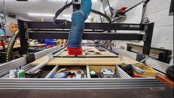
  1. Ted Moyer

    Ted Moyer New
    Builder

    Joined:
    Mar 20, 2017
    Messages:
    11
    Likes Received:
    8
    Ted Moyer published a new build:

    Read more about this build...
     
  2. Ted Moyer

    Ted Moyer New
    Builder

    Joined:
    Mar 20, 2017
    Messages:
    11
    Likes Received:
    8
    VFD GT Series wiring 7.5kw/4kw to Black box
    • I have a Vevor 4kw ER 20 Spindle
    • Powered by HY Huanyang VFD GT Series 7.5kw VFD. (This was an accidental purchase as I also mistakenly purchased a 7.5kw Spindle! WAY too big for home use! I was still able to use the VFD as they are infinitely programmable, And the GT series even more so proves that! WOW too many options.
    • Main difference between the HY series and the GT series is the level of programming needed and more options for more of an industrial machine.
    • After much trial and error, I am able to control the spindle speed and turn the spindle on and off with BB!!!
    • I can say that this VFD and spindle are an amazing value. Early on I couldn't control spindle with BB so I went to work and asked my wife and kids to turn it off when they went to bed. Well of course they didn't. The spindle ran for nearly 24 hrs straight!!! No fires, no obvious wear noted of any kind!
    • See below for the how to!
      1. 2 wire control = mode 0
        • Forward/Enable = S1
        • Stop = not connected
      2. Wire COM to BB COM
      3. Wire S1 to BB NO
        1. upload_2022-11-18_7-33-11.jpeg
      4. Relay jumper M3/M5
      5. Open GT series VFD bottom and top cover
        1. Remove J1 jumper from top two pins to disable speed control from keypad potentiometer

        2. upload_2022-11-18_7-35-21.jpeg
      6. Adjust your 10v output as needed
      7. Set P5.12 through 5.15 as needed based on your spindle
      8. Set VFD according to picture below
        1. upload_2022-11-18_7-28-42.jpeg
      9. Link above got me in the right direction you can follow exactly if you want to use switches however that will circumvent OB Control Software. Just change the 5.10 to 0 to get everything to work correctly.
     
    Rick 2.0 and Peter Van Der Walt like this.
  3. Peter Van Der Walt

    Peter Van Der Walt OpenBuilds Team
    Staff Member Moderator Builder Resident Builder

    Joined:
    Mar 1, 2017
    Messages:
    13,751
    Likes Received:
    4,070
    Wow wow wow! Awesome! The GT had bad rep here before. So super glad you cracked it :) well done! Mind if I link to this post from the documentation?
     
  4. Ted Moyer

    Ted Moyer New
    Builder

    Joined:
    Mar 20, 2017
    Messages:
    11
    Likes Received:
    8
    Go for it! That was actually my intent for doing it! Maybe...someone else could benefit!
     
  5. Peter Van Der Walt

    Peter Van Der Walt OpenBuilds Team
    Staff Member Moderator Builder Resident Builder

    Joined:
    Mar 1, 2017
    Messages:
    13,751
    Likes Received:
    4,070
    Definately, and we really appreciate the spirit and willingness to share information! That's what its all about :)
     
    Mark Carew and Ted Moyer like this.
  6. Ted Moyer

    Ted Moyer New
    Builder

    Joined:
    Mar 20, 2017
    Messages:
    11
    Likes Received:
    8

    So I'm having a bit of a tramming issue. You can see the details on the link and pictures to better answer .

    Screenshot_20221122_045322.png 20221118_022215.jpg 20221122_044125.jpg

    Solutions/questions I have thought of:
    1. Correct me if im wedding but I behind the main stiffness of the system hinges on how much contact and how secure the v wheels are correct?
    2. Adding a 2nd gantry plate with six wheels to the top of Z axis to give more to approximately 25lb 4kw spindle. This would add six more wheels of support.
    3. Incorporating mini wheels into z axis and inside cbeam so there are more wheels of support?
    4. Adding a 2nd gantry plate to the rear of both y axis to give less front and back twist similar to creating a custom plate like older CNC machines where they are wider at the base of the y axis. This would give me 12 more wheels or 8 of contact and another gantry plate worth of support to prevent the front to back rocking.
    5. Same as #4 plus another 20x80 for both y axis all attached with connecting plates of some kind.
    6. Getting rid of the vslot I using to mount the spindle and making a custom plate the size of two XL cbeam gantry plates .
    What is the best bank for the buck and adding rigitity etc?
    I've checked all my wheels and the corners connectors are all tight. Thanks in advance!
     
  7. Rob Taylor

    Rob Taylor Master
    Builder

    Joined:
    Dec 15, 2013
    Messages:
    1,470
    Likes Received:
    746
    Even a 2.2kW spindle is usually considered overkill for any of the OpenBuilds designs. 1.5kW and under is best- the wheels and frames can't take the weight and they definitely can't take the cutting forces; there's no point in putting a spindle on there that you can't really use the power of. I think around 8lb is generally considered the most spindle weight that the frames can reasonably take. Remember, the components themselves are basically designed for trim routers. Stronger/more rigid wheels help, but it's a material constraint more than an engineering one.

    1) Yes. 1500mm extrusions are surprisingly floppy despite how rigid they feel, and of course plastic wheels are compressible. I spent a lot of time coming up with a good-enough gantry design here, but plastic wheels were a no-go from the off: M4: 1510SS Heavy Mk.I

    2-6) Your loss of support is at multiple points, but the one that particularly jumps out to me in the picture is the tiny x-axis carriages carrying the gantry columns. Not enough wheels, not enough width. Doesn't matter how rigid the gantry is if the machine base can't support it.

    7) Best bang for the buck any time this side of 2018 is linear rail. It got so cheap, and its load/torque capacity is absurd.

    Basically, you need way beefier carriages, more substantial columns, maybe more gussets, maybe a backing strap for the gantry, etc etc. It needs to become a different class of machine- and you need access to a machine shop to make the parts- to run the type of spindle you want. Then, of course, the problem is that your motors are too small to move the heavier loads, so you have to upgrade those. Then you need bigger drivers, etc etc. That's the route I went, but it's a lot of work.

    The best options are either 1) Make the spindle a 1.2-1.5kW. That's about what these machines are designed for; probably around 5-10N of radial cutting force and 7lb of weight. Or 2) Make the machine much smaller, maybe 500x500. That would solve your gantry issues, though not your column/carriage issues.
     
  8. Ted Moyer

    Ted Moyer New
    Builder

    Joined:
    Mar 20, 2017
    Messages:
    11
    Likes Received:
    8
    Wow great info! I still have my 1.5 kw I could put back on there. I just wanted 1/2 collect so I can use big bits for turning with rotary axis.
    • I actually have 4 NEMA 34 with drivers never opened! From a build I was going to do.
    • Maybe if I get metal v wheels I could make it a bit better? Didn't think if that.
    • This is probably also why OB doesn't suggest or create a high Z mod on the 1515 and only on the 1010. This machine was a 1010 in it's former life...
    • Maybe I just make s dedicated turning machine with the monster spindle?
    Thanks again for the advice!
     
  9. Peter Van Der Walt

    Peter Van Der Walt OpenBuilds Team
    Staff Member Moderator Builder Resident Builder

    Joined:
    Mar 1, 2017
    Messages:
    13,751
    Likes Received:
    4,070
    :) We do have one! See Post #22 in OpenBuilds LEAD CNC Machine 1515 (60" x 60") - demand's too low for a "kit" but the full details are available

    Tramming: A generic guideline is a good read too - sure the heavy spindle is not ideal - and I do agree tightening things up to accomodate it wouldn't be a bad idea - but first make sure it is all perfectly trammed - the stepping in that surfacing job looks telltale
     
  10. Rob Taylor

    Rob Taylor Master
    Builder

    Joined:
    Dec 15, 2013
    Messages:
    1,470
    Likes Received:
    746
    2.2kW units do have ER20 options- that's what I have. At around 12lb, that's a huge difference vs your current spindle.

    That would work, but not with a stock BlackBox. You can solder/jumper external drivers from inside the Brains board, if you want to keep grbl. NEMA 34s can also twist hard enough to bend light aluminum framing- and can probably pretzel 8mm leadscrew- so be careful how much power you're adding to the system without additional strength and rigidity. I have closed-loop NEMA 34s so I can avoid them dumping that extra power when I don't want it.

    You could, and it would solve the problem temporarily, until the steel wheels start grinding out the aluminum extrusion under all the load. Machines with any power have oiled steel-on-steel motion components for a reason.

    Peter linked the details, but it would be arguably more important to have a High-Z on a 1515.

    That would probably make sense. As soon as you get above 3kW, you're out of the realms of hobbyist aluminum framing, really, unless you're doing ultra-high-speed stuff and have to contend with crazy torque curves.

    Yeah, doesn't matter what spindle you have if it's not square to the workpiece. Though the weight of a large spindle is going to affect the gantry extrusion differently as it travels in x- more twist in the middle, less at the outsides, so the precision and consistency you can get in nod is gonna be somewhat limited, even independently of cutting forces. Large surfaces will just need extra finishing work.
     
    Ted Moyer likes this.
  11. Giarc

    Giarc OpenBuilds Team
    Staff Member Moderator Builder Resident Builder

    Joined:
    Jan 24, 2015
    Messages:
    2,899
    Likes Received:
    1,613
    Have you tried 1/4" shaft by 1/2" cutters? Also, a Makita can use 8mm collets and you can get ER11 8mm collets. I cut very quickly with 8mm ball nose endmills with my Makita on my rotary axis (and regular 3D carves). [​IMG]
     
    Ted Moyer and Peter Van Der Walt like this.

Share This Page

  1. This site uses cookies to help personalise content, tailor your experience and to keep you logged in if you register.
    By continuing to use this site, you are consenting to our use of cookies.
    Dismiss Notice