
25/02/18
Welcome to my second build !!
An example of Machines building Machines......
Yes I have come back for more, My C-Beam XL has been an outstanding success and I have wanted to have laser capability for a while, so here I am and I have put my "Moagie Mill" to work to build his brother "AcroCadabra"
Why the Name "AcroCadabra" well I Milled the plates from nothing more than some scrap Poly Carbonate that was left over from another job that I was doing.
I also have a few spare bits left over from the C-Beam XL so I thought, why not build this thing from virtually nothing and Hey "Presto" I will then have an Acro Laser unit.
I want to have a detailed documented build for others to reference, I did that with the My C-Beam XL build also and I really think it is worthwhile for other builders that come after me so they have something to reference when they are doing their build.
So I started out on the project last weekend and started cutting the plates.
I have since done an inventory of what I need to order from the parts store to get the mechanical build done.
Today I finished cutting the last couple of plates so I am now ready to order my bits.
I cut the plates from Poly Carbonate, a Really strong plastic and it is a plastic worth learning how to cut. It is very different from Acrylic, It melts onto your cutter very easily so you have to get the feeds and speeds right otherwise it can get pretty messy pretty quick and you can end up with broken cutters and damaged stock, it also has a tendency to be pulled up the cutter so you really need to clamp the stock down well, especially if using larger cutters.
Here is my Plate set, fresh off the C-Beam XL.

I used Sketchucam to generate the G-Code from the Sketchup Plans.
The Sketchup plans can be downloaded here:
https://openbuilds.com/builds/openbuilds-acro-system.5416/#openbuilds_files
I also use Camotics to got through tool path simulation before I go anywhere near the C-Beam to cut anything, It is surprising how many times that simulator has saved me from mistakes and wrong settings when coding the job.
I cut with Mach3 on the C-Beam XL.
I cut these plates using a 1mm End Mill.
Multipass Cuts at 0.25mm depth of cut.
Feed rate 600mm/Min
Plunge Rate 40mm/Min
12000rpm on the router.
So not the fastest way to cut them but I got a good result and at the end of the day that's what counts. One thing I have learnt over the past year or so cutting parts is, you can cut like a bat out of hell and get a crap finish or you can just take your time and slow it down, maybe make smaller multiple passes and you get a much nicer finish.
I think Poly Carbonate is a good choice for the Acro Laser plates as I have read on the Acro build thread someone cracking their OB Acrylic plates, most likely from over tightening screws or forcing something that should not be forced, Acrylic is pretty unforgiving in those circumstances and will crack pretty easily under stress.
Poly Carbonate on the other hand can withstand those types of forces and to give you an idea on its strength, it is the material they make bullet proof glass out of.
I built my CNC Clamps from the same stock that I have built the Acro Plates from and they are put under enormous stress every time I clamp stock down.
Maybe OB should consider offering Poly Carbonate plates if they get a lot of reports of plates being cracked..... Just a thought.
Most people seem to build their clamps from plywood which is strong but I have chosen the Poly Carbonate for mine due to its elastic properties.
Here is a picture of my clamps under stress holding down some stock for milling.

So that is it for now, I will continue with my log once I receive my order of bits, I still have to decide on what size I want to go but I am feeling that I will stick to something that is slightly larger than my C-Beam XL.
Cheers Glenn.
01/03/18
OK I settled on a Size....
I have gone with 1000mm V-Slot all round, that should give me at least an 800mm x 800mm working area and should be fine for most things I would want to tackle.
The nice thing about this OB gear is if you need to go bigger later, it is very easy to upgrade an existing build.
So I placed my orders for the bits I need, again I got some locally in Australia from the Maker Store which turned up within 1 Day, and the parts I could not find there I ordered from the OB parts store.
So I am still waiting on the OB Delivery at this stage.
I have ordered my parts as per the standard parts listing on the OB Acro System, so the only variation is the V-Slot lengths which are all 1000mm.
You can find the list here:
https://openbuilds.com/builds/openbuilds-acro-system.5416/#openbuilds_parts_list
I want to fit a Z Axis on this unit too, I have read that it makes focusing a breeze but also will allow cutting of thicker material as you step down over multiple passes to get through thicker stock.
However that will be a modification a little later for now I just want to get a motion system in place.
I am not going to order the laser diode just yet either, I have not done a lot of research or reading on the different diodes available just yet.
I have just finished putting the Wheel Kits together, I am using the Extreme V-Wheel Kits, Yeh they are more expensive and probably not required for this build as there is not a lot of stress on the wheels but I figured that it would be good to have some spares for my C-Beam XL in case something goes wrong with one of the wheels on that unit.
It is such a pain putting these wheel kits together and I have just thought of a brilliant Idea.
OB Should release a Z-Axis type of Press Kit that can simply press the Bearings into the wheels for you, I would build one cause I am already over pressing the bearings into the wheels and I only had to do 12, that's my gripe for the day !!
A Nema 42 will do the trick...... I reckon... LOL.
Just like this one:

Here we go, 12 Wheels ready to ROLL.

03/03/18
OK now to the serious stuff...
My V-Slot Extrusions arrived true and square and exactly 1000mm Long so I do not need to even touch them, no cutting or filing and did not even have to look at the Mitre Saw, That saved some time.
Today I Tapped M5 Threads into all the ends of the V-Slot, I did both the 20x40mm and the 20x20mm beams on both ends. I know that the 20 x 20mm beams did not require tapping but I thought I may as well while I am setup to do it and it is much easier all pulled apart that when on the machine.You never know the exposed tapped holes may become handy for fixing something to the machine at a later date.
I know from the C-Beam XL build that you are always adding things or doing mods to the platform once you get up and running, so I thought I would spend the extra 15 Minutes and tap the 20x20's just in case, if nothing else I can now tidy it up by screwing end caps onto those cross beams.
I tapped my threads all by hand, no drill taps were used.
I prefer to take my time and do it the old way, I used some WD40 instead of Kerosene this time and I think it was a much smoother thread cut.
I am using all M5 Threaded screws and will not be using any self tapping screws on this build, that is a slight variation to the standard Acro Build.

I used a cloth around the V-Slot so the vice does not damage it, being careful not to tighten it up too much.
When tapping I usually do a Half turn clockwise and then back off Quarter turn anticlockwise with a back and forth action on the quarter turn, than a further half turn in again repeating the action.
I used a Tapered Tap, this makes sure the Tap finds its way into the hole at the right angle without you having to worry about it too much, if you use a Plug Tap it is easier to mess it up but still doable.

I normally go halfway into the hole and then back completely out to clear the build up with some compressed air, then add some more lubricant and finish the thread off. I went as far as I could with the Tap as this means I should have some extra thread in there should the unthinkable happen, and I strip the thread for some reason when doing the build, it's just a little safety net for when bad things happen.


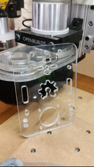
Today I am also preparing the Clear Polly Carbonate plates by giving them a spray of Matt Black Acrylic paint, I did not want to use clear plates, although it would have looked cool.
I really do not want dangerous spurious laser light being refracted all over the place through the clear plates.... So they have now been given a few coats of Matt Black, now they are not cool anymore but sexy !!
It also will go really nice with the black Anodised V-Slot too.
Here are some of the plates with a few coats of the Matt black Acrylic paint.
By the way my little Lazy Susan you can see here in the photo is what I use when spraying small items, it makes it easy to spin the items around while spraying giving a nice even coat.
This saves me running around the part when painting.

The Lazy Susan was built with my C-Beam XL.... It is basically a base board that can be clamped to the work horse with a bearing wheel that connects/bolted to the round table. I use it heaps.
Anyhow once these plates dry, I think I am ready for the real fun and will start assembly.
At the moment I am still waiting on the timing belts and timing pulleys form the OpenBuilds parts store and few other little items that were not available locally, but I have most of the parts I need to get stuck right into the build now.
Cheers Glenn.
06/03/18
Well I have started assembly today, however I am still waiting for the OpenBuilds parts to arrive.
They should be here any day now.
As I started looking at where I am going to assemble this thing besides the floor, I realised I actually do not have a bench large enough in depth to carry it. It is easy to get excited and start building a machine/project and later realise you have not got anywhere to put it, I am probably not the first person that has done that trick !!
1000mm Depth certainly is not standard for many benches so I decided it was time to upgrade my mobile workshop bench and put a larger top on it that would facilitate the build and will most likely be the place where I will operate the unit.
You may recall this bench pictured here when I was building my C-Beam XL.

This is the mobile workshop bench I was referring to, it is on wheels so I can move it around, but in this picture you can see it is not deep enough to house the 1000mm Laser build and the bench top has seen better days, it is only about 800mm deep.
So I decided to remove the bench top and replace it with a new piece of laminated MDF that I have had laying around here for years waiting for that perfect moment to be used....
Finally I have a use for it, I am so glad I didn't throw it out !!
So here it is with a new sheet on it, I have not fixed it to main structure yet but it will be god enough to continue the Laser build on and get it to a finished state.

So I have migrated all my parts down to the workshop where I will now do the final assembly.
As I have been watching the Build Video from OpenBuilds Youtube channel and assembling the plates etc. I realise just how simple the build actually is compared to the C-Beam XL, there really is not much to this one and would be a perfect introduction kit for a first time project for anyone contemplating diving into the deep end for the first time.
The OB Youtube Assmebly video for this unit can be found here and very easy to pause and follow along with.
Here you can see I have started at least, I can't go any further just yet until the Timing Belt Pulleys and Belts arrive from OB, It should fit nicely on this bench top though, I will most likely trim this bench top back a bit too when I get a chance, it is probably a little bit too wide, Some Aluminium Angle re-enforcement on the edges may not go astray either, it is only MDF.

Her is big Brother in the background, or should it be Mother... After all the XL did give birth to the Acro plates !!

More once the OB Gear arrives......
Cheers Glenn.
08/03/18
Well I received my OB Package yesterday, So I could now finish off the main build.
I was waiting on the drive belt and pulleys , a few various screws and some extra 6mm spacers.

I got a another Makers sticker too, I need to wack that somewhere good and take a photo for the "OB Was Here" thread, I will be more creative this time.
So I couldn't help myself, I just had to fit it all up last night, It really did not take long at all.
The Plates that I made were all spot on and it all went together like clockwork.
I just followed the OB Video and just paused at each major step.


There is a couple of things I would like to pick up on in the video though.
The first one is the fitting on the 90 Degree corner brackets that connect the gantry to the Y Motor Plates.
This is what is shown in the video, and looks like somebody is in a rush here....
Must have been lunch time !!

The corner brackets properly fitted should look like this:

The other thing I noticed was that the timing belt clamping was not consistent throughout the video.
It is advised that the T nuts should be locked down at least 20mm from the end of the rail, It is noted by text on the video but not shown to be done that way.
It is also clearly noted that the use of 5mm low profile screws is incorrect and they should really be 5mm Grub Screws.
Maybe it was dinner time by this part of the video !!

Anyhow it should really be locked down something like this:

I am not trying to put down what is otherwise a very excellent video guide, I am just making sure that somebody that might be putting one of these together doesn't make these mistakes and I am just bringing it to the readers attention.
Here is a close up of the Belt and pulley profile on one of the Y Axis Motors so you can see what it should look like.

Once the belts are locked down and the pulleys engaged to the belt properly it should be a smooth but firm movement along the beam when you move the plate back on forth and there should be no binding.
Be sure that the Pulley is aligned perfectly centred to the middle of the beam and wheels when fitting the pulleys to the motor shafts.
Once I had done all the fiddly bits with the pulley alignment and belt locked in and tight, the sub assemblies went together easily, just following along with the video, fitted the Y motors/plates to the gantry and then moved the gantry to one end to fit the cross rail, this gives you the correct spacing between the two Y rails and then did the same with the other end.
First the rear end...

Then I moved the gantry to the front and fitted the second cross rail.

That was pretty much it, It was an extremely quick and easy build, it took me longer to cut the plates to be honest, but that's all part of the fun "Making stuff".


I cannot call the build finished at this point because it certainly is not operational, this weekend I hope to get to the electronics and actually do some controlled motion.
I will be using a Protoneer CNC Shield for the Motion Controller, I am fairly experienced with Arduino programming/Loading so that should be fairly easy to get going.
I will log my experiences here with the Arduino/Protoneer Shield as I go through it.
On my last build I promised myself to never try all this again without fitting limit switches first up, the sound of an Axis crashing into its stops is not a nice sound.... So I am going to pickup some more hall effect sensors, the same type I used on my C-Beam XL, It is probably a good time to design/cut a little housing for them as the ones on my C-Beam XL are still exposed, they work fantastic too by the way.

More soon......
Cheers Glenn.
09/03/18
Moving right along..... Now its time to play with motion control.
This is where I feel lost sometimes, but I can assure you if you keep playing long enough all the pieces start to make sense and come together.
One thing I did not do on my C-Beam XL Build was document the electronics part of the build very well, certainly not details on getting MACH3 going and getting those first steps with the motors, I wish I had of..... I think I was just too excited at the time to sit and document it all.
This time I am going to document all the stages I go through right to the final wiring.
It may be some lengthy reading but it may help get others on their way a little quicker.
I will be documenting the process of setting up the Arduino UNO with Protoneer CNC Shield + Pololu A4988 Stepper Drivers with GRBL 1.1
The reason I went with this was simply because I already have a few Arduino's laying around here looking at me with nothing to do. I had purchased the Protoneer CNC Shield back when I got serious about building the C-Beam XL, only to realise the drivers could not handle the current required to drive the NEMA 23 Steppers on that machine, so it went into storage for another day and that day has arrived.
So first up, as I mentioned I am pretty comfortable with Little Arduino Micro's.
I have been programming them for other applications for a few years now..... that's another hobby in itself... lets not go there. All we want to do is program the GRBL Code into the Arduino attach the CNC Shield and stepper Drivers get some software going that can talk to the GRBL firmware in the Arduino and control the motors.... It sounds simple but there are quite a few steps involved to get there.
Just a note for any new comers not familiar with this Arduino Thingo.
What is it you might say ?
Well think of it like a little miniature computer, not a very powerful one but it has all the things that a very basic computer needs to run a program, the programs are called sketches in the Arduino world.
GRBL 1.1 is a Sketch that we upload into the Arduino that makes it a dedicated CNC Controller.
Like we load programs on our big computers to get a job done, such as MS-Word for Word Processing and MS-Excel for spread sheets we load GRBL onto our Arduino to turn it into a GRBL CNC Controller, however it is very limited in resources and is a single threaded device it cannot multitask like our big machines, so we load only one program into it at a time (A Sketch)
Why use an Arduino if it is not a very powerful computer ?
1) Because they are very cheap
2) well supported in the maker community, they themselves are an open source design.
You too, just like you build CNC Machines here from open source plans can actually build an Arduino Board from open source plans and sell them.... but china will prohibit you from going into production because they produce them so cheaply that you will never get your Arduino board to market.
3) They are dedicated to the task with no other interruptions unlike MACH3 parallel timing issues experienced on printer ports under the windows multitasking environment because MACH3 has not got the CPU attention all of the time.
So all that taken into account makes them a perfect candidate for a CNC controller.
What is a "SHIELD" ?
A Shield is another name for a daughter board that is connected to the main board (The Arduino).
A shield usually gives us access to the INPUT/OUTPUT pins on the Arduino so we can interface and interact with the real world from a sketch.
For example we can read the status of a PIN (HIGH/LOW) or we can set the status of a PIN (HIGH/LOW) all from within a sketch that is running on the microcontroller. We can also read/write Analog values as well on selected PINS.
Shields are also stackable, so it is not uncommon to see several shields stacked on top of the Arduino main board, there are many shields out there that do all sorts of things.
The CNC Shield has been designed to make it easy to connect up stepper motor driver boards, motors and limit switches etc. and that is why it is called a CNC shield, of coarse the shield would be useless without the GRBL Firmware (Sketch) loaded onto the Microcontroller.
I hope that clears up some mystery surrounding these clever little boards, they don't look like much but they can entertain you for years all on their own if you start to delve into the world of Microcontroller programming.
So lets get down to business and get our Arduino prepared for CNC Controlling, at this stage all we need is an Arduino, we don't even need the shield. The first step is to get GRBL on the board and verify it is behaving as a GRBL Controller.
The first thing you need is the Arduino IDE (Arduino Integrated Development Environment)
The Arduino IDE is the environment (Windows Program) from where we upload sketches into the board, it is also the place where you can write a Sketch of your own and upload it into the board, there are some example sketches already written for you that you can upload to see what they do.
There is one under the Basic section called "Blink" this will load a sketch that simply toggles PIN13 High/Low and will make the built in LED on the Arduino UNO blink ON/OFF once a second.
Give it a try sometime, you never know what you will discover once you enter the world of microcontrollers........
But for now lets stay on track and get our Arduino IDE Installed into Windows.
Download the Arduino IDE that suits your computer from here:
Arduino - Software
At time of writing this the current version is 1.8.5
I am currently running 1.6.5 here.
If you need assistance installing the IDE, there are some great video tutorials on youtube to get you going, just have a search and there will be plenty to choose from. However the install should be pretty straight forward.
The Next thing we need now is the GRBL 1.1 Firmware, it is available from here:
https://github.com/Protoneer/GRBL-Arduino-Library/archive/master.zip
Now I am also going to reference the protoneer site here because they have some great guides that takes you through the process to get up and running with the CNC Shield, it is in their interest to get you going because the CNC shield is useless without the firmware on the Arduino.
It also links you to their Ebay store to purchase a CNC Shield if you need one.
So please take a look at these guides:
Arduino CNC Shield – 100% GRBL Compatable
Arduino CNC Shield V3.XX – Assembly Guide
Quick GRBL setup guide for Windows (Arduino G-Code Interpreter)
GRBL Arduino Library – Use the Arduino IDE to flash GRBL directly to your Arduino
You should be able to get the GRBL firmware onto the Arduino after going through those guides and I do not want to replicate all that here, so spend some time reading through those links.
Once you have the GRBL firmware loaded into the Arduino we can proceed to start testing it.
In the Guides above they talk about using Universal G-Code Sender, I didn't bother with that, You can cross check right from the Arduino IDE to see that it is behaving correctly.
Some key settings for the Arduino IDE are:
1) Make sure you Board type is correct.
Check under "Tools" "Board" and make sure it is set to "Arduino/Genuino Uno".
2)Make sure the correct COM Port is set correctly.
Check "Tools" "Port" and set for your correct port number, it will be different to mine.
3)Make sure the Baud rate is set correctly.
Check "Tools" Serial Monitor", If the IDE is talking to the Arduino the Serial Monitor window should open, down in the bottom right corner of that windows select the Baud rate to be 115200.
If you have loaded the GRBL Firmware correctly you should see some text in the serial monitor window.....It should read:
Grbl 1.1f ['$' for help]
If it does then you have successfully loaded the firmware and little Ardduino is now a GRBL CNC Controller.
If you type "$$" without the quotes into the Send line and hit Enter, you should get a response back from the controller in the main windows like this:
$0=10
$1=255
$2=0
$3=6
$4=1
$5=0
$6=0
$10=0
$11=0.020
$12=0.002
$13=0
$20=0
$21=0
$22=0
$23=1
$24=25.000
$25=500.000
$26=250
$27=1.000
$30=1000
$31=0
$32=1
$100=114.290
$101=114.290
$102=114.290
$110=10000.000
$111=10000.000
$112=10000.000
$120=2000.000
$121=2000.000
$122=2000.000
$130=1000.000
$131=1000.000
$132=1000.000
ok
ok
That is all you need to know at this stage to verify you board is operating correctly from a software/firmware point of view.
The next stage is to now start setting up the CNC shield.
Then we will connect to the board with some CNC Control software configured to talk to a GRBL controller and see if everything verifies OK.
In my case I am going down the LaserWeb path, so that's what I will be going through here.
Stay tuned I will be back with more soon.
Cheers Glenn.
10/03/18
OK The next step is to start dealing with the CNC Shield.
You may have noticed when I type the "$$" command above that I have already loaded the settings
posted in the Acro build Log here, under Machine Settings:
https://openbuilds.com/builds/openbuilds-acro-system.5416/
You can type the 34 "$" Commands and there associated values in the Send Window from within the Arduino IDE. The descriptions in the brackets are not required.
For example the first command: $0=10 (step pulse, usec)
You only have to type $0=10 into the SEND window.
Do this for the whole 34 Commands and you will have now set all the settings required to get going.
This will save the settings into the Arduino and they will be remembered even when power is removed from the Arduino. You can verify all the settings have loaded correctly by typing "$$" in the SEND window from the IDE and the Arduino will spit out al the current values which you can cross check against the advised values in the Acro build post.
Now to the CNC Shield.
It is advised in the Acro build thread to set the Controller to 1/16th step.
This is done on the CNC Shield with three jumpers underneath each driver (12 Jumpers in Total).
So you will have to remove your little driver boards from the sockets if they are installed to set the jumpers.
Here is a picture of My Version 3.00 CNC Shield.


This information was gathered from A4988 Driver Jumper Link settings table, you will find the table at the Protoneer web site, see previous links above.
Here is the table for the A4988 Drivers settings.
In the tables below High indicates that a Jumper is insert and Low indicates that no jumper is inserted.
Pololu A4988 Stepper Driver configuration:
MS0 MS1 MS2 Microstep Resolution
Low Low Low Full step
High Low Low Half step
Low High Low Quarter step
High High Low Eighth step
High High High Sixteenth step
The next important setting on the CNC Shield is to Clone the Y-Axis to the 4th stepper driver(Marked as A)
This is done by putting two links here:

Now we can Install the Driver Modules onto the Shield and plug the shield into the Arduino.
Be sure to power OFF the Arduino while doing this, it is not good practice to plug things in live, you will more than likely blow something up doing that.
So remove the Arduino from power and/or USB and make sure there are no lights ON.
Also be very careful about the orientation of the driver boards when plugging them into the Shield.
They should be Oriented like mine but ONLY for the A4988 Drivers, Be sure to triple check your driver boards. Other Driver boards can and will look much different, so be very careful with the driver fitting at this point, or you will blow up your driver modules at power ON.
The best way to confirm orientation is to match the "ENABLE" Pin on the Driver board with the "EN" Pin on the socket on the shield.
Here mine are fitted correctly.

Now place the shield onto the Arduino.
We are ready to Install LaserWeb and see if it behaves as expected before connecting any motors.
I am new to Laserweb so bare with me... this could be the blind leading the blind but I should be able to get some motion happening as I know what I am looking for and what needs to happen.
Also as I was writing up this build I received a notification from @MaryD to say I have been selected as one of the finalists in the "Power Pack" Competition that finishes on the 23rd of March.
If you are reading this and it is before the 23/03/18 and you find this build informative, Please post a Vote for me if you have a second..... I don't have a power supply for this unit yet so it would be pretty awesome thing to win one..... Thankyou for the Opportunity @MaryD.
You can place a Vote for my build here:
https://openbuilds.com/threads/poll-cast-your-vote-powerpack-contest.11919/#post-66007
I will be back soon with a demonstration of my motors running hopefully and will go through the connections to the CNC shield.
Cheers Glenn.
15/03/18
OK Well I did mention it could be a case of the Blind leading the Blind.... LOL
I hooked up the motors, Installed Laserweb expecting everything to just work and got a big FAIL !
I could not for the life of me get any movement at all, however I could hear the motors clunk as I connected to the controller so I knew there was life. The Little clunk that you hear when powering up a CNC machine is normal and is a sign that the motors are being powered and are now locked in their current position. Stepper motors are different from normal motors, they draw current even when stopped because the windings are powered to hold position when stationery.
I will go through getting Laserweb up and running in details but first I want to take you through my fault finding adventure that lead me to finding the problem and achieve motion.
There is one thing for sure when building your own CNC system, be it laser, router, plasma, 3D Printer or whatever, there is an incredible mount of choice when it comes to motion control.
It takes quite a bit of reading and investigation to work out what will be the best choice to go with.
There is much to consider such as Price, Power Rating, Replaceable or Onboard Motor Drivers, USB Interface, Ethernet Interface, Parallel Interface (Older but still used).
To be honest it is a minefield to navigate and anybody could be forgiven for purchasing the incorrect items thinking that they would do the job only to find out later they had wasted their money and should have purchased something else, that's what happened to me with the C-Beam XL and is why I have an Arduino CNC Shield at my disposal, it simply could not handle the current required to drive the Nema 23's used on the C-Beam XL and I only found out by a lot of reading when it came to wiring up and configuring the motors/electrical side of the build.
The CNC Shield is perfect for the NEMA 17's in the Acro build, and because I had a unit sitting here doing bugger all, was why I thought I might as well build the laser system and put it to use.
Well you may have noticed that the OpenBuilds Acro build is designed around the xPro CNC Controller which is a GRBL controller too, but certainly nothing like the Arduino/CNC Shield Combo.
It is a totally different hardware design.
So in my haste to get everything running I copied the complete set of GRBL Config lines straight into my Arduino GRBL Controller but that config was for the xPro CNC Controller.
So that is where I made my big mistake, that took some time to resolve.
It is always when you take shortcuts and make assumptions that things go pear shaped.
I have worked in the service/repair industry for 37 Years, and still do, if there is any advice I can offer to somebody building their own machine that find themselves lost, frustrated and helpless when something just is not working how you expect and you are ripping your hair out........ Just STOP, Put down your tools, Walk away even if it is for a Week, give yourself some time to think things over and think about where you are at with the project, think about all the knowns, think about the unknowns, do some more research and if you cannot find an answer in that time then return with a different approach and do what I call coming back to basics.
I have fixed so many problems when facing a frustrating situation just by walking away for a while, sometimes it might be only an hour and sometimes it just needs to be longer but I can assure you it works.
This is exactly what I did with the CNC Shield, I spent most of last Sunday trying to fault find why the motors would not run.
I simply could not get the motors to move, I did more research and found that my CNC Shield is a Physical Version 3.00 and that particular version was designed for GRBL 0.8, not only that but the current Version of the CNC Shield is Version 3.51 and it is designed for GRBL Version 1.1 which is the current version of GRBL and is what is required for Laserweb.
I also found out the differences between V 3.00 and V3.51 were:
1) Pins 11 and 12 Have been swapped to access PWM Signalling on the Arduino for Laser Output control.
2) Capacitive filtering has been fitted on the LIMIT SWITCH lines to stop false triggering that has plagued the Arduino's for some time.
At first I thought I was up for a new board but I certainly did not feel that this was the reason I could not get any motor movement.
So I decided to take the "Back to Basics" Approach.
I know that many before me have used the V 3.00 Shield with GRBL 0.8 for many projects with great success, I have seen people with that combination use Universal G-Code Sender and get things going pretty easily. So I Decided this is where I have to start from, go back to a KNOWN starting point that should just work.
I had already done all the obvious stuff, I verified the Winding pairs by shorting pairs of wires together on the motors, without power, feeling for a mechanical resistance when turning the shafts, This tells you you have a coil pair when there is a mechanical resistance in the motor shaft.
That was a great trick I learnt when building the C-Beam XL.
I had also verified the CNC Shield Motor Pin Outs to be sure they were connected to the appropriate windings correctly.
So I flashed GRBL 0.8 onto the Arduino, Installed Universal G-Code Sender, Dropped the Baud rate back to 9600 (That's what 0.8 Required) and "SHAZAM" ..... I had motion. I could now JOG the X Motor back and forth. So now I had a starting point, I then proceeded to plug in each motor onto the X Motor driver (Powering down in between connections) to verify all motors were operational.
Next I powered down again and inserted the Y and A Driver Modules (A is Slaved to Y in my config).
I connected up all the motors, and after a small JOG I realized I had to swap the A Motor around so it would travel the same direction as Y, and I was in business, I had full X/Y Motion Jogging from within Universal G-Code Sender.
This meant it had to be something I was doing when moving to Version 1.1 or Laserweb.
I first tried Laserweb but it complains about GRBL 0.8 and says you require at least GRBL 1.1
So I thought OK well I will stick with Universal G-Code Sender and move back to GRBL 1.1 on the Arduino, it should still JOG the Motors.
So Moving to GRBL 1.1 now but NOT sending the 34 $ Commands this time like I had previously done reading through the ACRO Laser Build, I was now able to JOG the Motors just like back on GRBL 0.8.
So Now I went back to Laserweb now that I had motion, reconnected to the controller at 115200 Baud which is the required speed for GRBL 1.1 and I finally had motor control from Laserweb.
This clould ONLY mean that the issue was one of the 34 $ Commands that I had assumed would just be correct for my controller BUT I was WRONG !!
So one by one I started typing in the suggested GRBL Config Commands, testing Motion in between each command, then found the culprit, it was the $4=1 (step enable invert, bool) that was casing my issues initially. This is the point at which you feel stupid for taking shortcuts and not understanding the real reason why you are setting something or doing something that you have read.
This makes perfect sense now, as different controllers use different logic levels for sensing an ON/ OFF or 1/0..... Stupid me, I threw away a Sunday afternoon just because I did not bother to look at what each of these commands actually do and did not stop and think for a second that those commands just may NOT ALL apply to the Arduino/CNC Shield.
So I set $4 = 0 and I was all happy again and my hair started growing back immediately.
So be very aware of what your controller is looking for when configuring your software/firmware, cheating and copying from another build that is using a different controller than yours such as I did, can cost you time and frustration.
So here is my current configuration, I am yet to double check final calibration etc. but these settings should get you going if you are going to go down the Arduino/CNC Shield Path, you are welcome to copy them of you wish, I take no responsibility !!
$0=10
$1=255
$2=0
$3=6
$4=0
$5=0
$6=0
$10=0
$11=0.020
$12=0.002
$13=0
$20=0
$21=0
$22=0
$23=1
$24=25.000
$25=500.000
$26=250
$27=1.000
$30=1000
$31=0
$32=1
$100=114.290
$101=114.290
$102=114.290
$110=10000.000
$111=10000.000
$112=10000.000
$120=2000.000
$121=2000.000
$122=2000.000
$130=1000.000
$131=1000.000
$132=1000.000
I really wanted to post this up as it may be something that will catch others out too, in fact I have no doubt at all, it will.
I will do a small Video of the system running and show some specific wiring diagrams.
I have since been able to open up a G-Code file that I have previously used on the C-Beam XL and MACH3, Load it into Laserweb and watch the machine do its "MAGIC"...... No Laser attached yet cause I haven't got one, just watching the motion is a lot of fun in itself though.
I guess the next thing to do now is to calibrate the machine and fine tune those GRBL settings and watch some tutorials on Laserweb to learn how to use it.
Cheers Glenn.
30/04/22
Well you know how it is, you start a project and never finish it....... well lets just say projects are never abandoned they just get put on hold.
It has was March 2018 since my last update and I have to say I really have not progressed on this build, but it has been in the back of my mind the whole time.
So much has happened since 2018 that its not even the same world anymore, well it feels that way anyhow,
I actually ditched the idea of using an Arduino/CNC Shield as a controller and did a sensible thing and purchased an Openbuilds Blackbox, not long after the last update. So as you do, I had a change of plans mid build, I also realised I wanted to fit limit switches and a controllable Z axis to the machine so this all contributed to the hold I guess, then other things got in the way, like life and other more important things to do.
I also ended up purchasing an Opt Laser PLH3D 6W Laser that has also been sitting in a box for all these years.
Anyway it has been resurrected and I am now back on the build.
Things to be done.......
Fit the BlackBox and wire it up.
Build and fit a Z Axis with mini stepper motor so it can be controlled via software.
Fit the Laser head.
Fit Drag chains for cabling and Air assist pipe.
Fit Air assist.
Build an enclosure with Exhaust to remove smoke and fumes.
Cannot think of anything else right now but I am actively building the Z axis and have gone with a design I quite like from another builder here on the forum.
I quite liked the low profile design of the Z Axis built by @Romamaker here on the forums
Here is his Z Axis Build: Z Axis for ACRO
Thanks again Romamaker !!
He listed all the required parts to order but forgot to include the 3D Printed bracket for the Stepper motor and the plate profiles for the new plates, so I dropped him a line and he was very kind and dug up the files for me, which I really appreciate because it saved me a lot of time.
The original files are available on his build discussion.
I managed to cut the plates in 6mm Acrylic on my good ole girl, the C-Beam XL that I built years ago... Love that machine.
I imported the DXF Plate files into Fusion 360 and extruded to 6mm to generate the tool paths so I could cut them. Since I last updated my build here I purchased a Elegoo Saturn 3D printer and am just about to print the bracket today and then I should be able to start assembly of the Z Axis.
Will be back soon with some pics.
Cheers Glenn.
01/05/22
OK Got some pics to show.... I CNC cut the plates from some scrap 6mm acrylic, the large plate & Spacers were white and the small plate clear, so I also sprayed them all matt black to reduce laser reflections.

Here is the full assembly from a few different angles, I think the 3D printed motor bracket need to be redesigned as I could only fit the two outer screws for the stepper motor, not that it really needs all four mounting screws in place as there really is not going to much force acting on the motor and lead screw so it is fine as is and am not really going to worry about it, it all feels quite good and will do the job nicely.
I have not made a final decision yet as to what length I am going to cut the rail & lead screw back to, will probably fit it to the machine first and I believe the Opt Laser's optimum focal point is 60mm so that will determine a a few things.


Now one little issue I ran into as I did not look at it closely is that the mounting plate for the laser was designed for the laser to mount directly to it which is fine but I have the Docking unit and the mounting holes for the dock are a different size and different location so I have decides I will probably print a little adaptor bracket rather that cut a new plate. I will attach that file here once it is done so anybody else that finds them in that situation can use it too.
Here is what the docking plate looks like next to the mounting plate, I can't really drill holes into the plate because there will be interference with the wiring connector and existing 5mm wheel screws and there is interference with the nut block too, will just be easier to do the adaptor plate and will not add much to the profile.

Cheers Glenn.
"AcroCadabra" My Acro Laser built with my C-Beam XL
Build in 'Laser Cutter Builds' published by Glenn Weston, May 1, 2022.
Well I built a C-Beam XL around a year ago, I am still learning things as I make stuff with it, it has been quite a wonderful learning experience. Now I have gained enough confidence and knowhow to Mill the required Plates to build an Acro Laser System using the Acro Laser Sketchup Model. I have pulled the Model apart in Sketchup, isolated the Plates and generated the G-Code to cut/Mill the plates. I have used Sketchucam to generate the G-Code. I Use Mach3 on my C-Beam XL to Mill.
-
-
Build Author Glenn Weston, Find all builds by Glenn Weston
-
- Loading...
-
Build Details
- Build License:
-
- CC - Attribution - CC BY
Reason for this Build
I built this Because I Can.... However I also wanted to give myself a challenge and see if I could build it from the 3D Model published at Openbuilds and utilise my C-Beam Xl to get me there. It Will also be very handy for fine engraving which is something I do on the C-Beam and using laser will give me more options with different materials.Inspired by
Openbuilds themselves, they are dedicated to the builder community and I am grateful to be part of that community.
