Welcome to Our Community

Some features disabled for guests. Register Today.

Sphinx Evo

Discussion in 'CNC Mills/Routers' started by Michael.M, Feb 5, 2018.
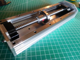
  1. Michael.M

    Michael.M Veteran
    Staff Member Builder Resident Builder

    Joined:
    Jan 21, 2017
    Messages:
    432
    Likes Received:
    264
    Michael.M published a new build:

    Read more about this build...
     
    CNCMD likes this.
  2. Michael.M

    Michael.M Veteran
    Staff Member Builder Resident Builder

    Joined:
    Jan 21, 2017
    Messages:
    432
    Likes Received:
    264
    Here's the Z axis Z snap 7.JPG Z snap 6.JPG
     
    GrayUK likes this.
  3. Michael.M

    Michael.M Veteran
    Staff Member Builder Resident Builder

    Joined:
    Jan 21, 2017
    Messages:
    432
    Likes Received:
    264
    Rail Orientation
    1) Carriages & Rails on the side of the machine

    2) Carriages & Rails facing upward on top of the Y axis extrusion

    What do you think? I have been reading and most people say the that the rails on top of the extrusion, facing upward are the strongest orientation. Of course this dramatically changes the gantry plate design.
     
  4. Sprags

    Sprags Well-Known
    Builder

    Joined:
    Nov 23, 2017
    Messages:
    154
    Likes Received:
    13
    When I worked for DMG MORI I assembled a few machines. On the DMU 50 machine made by DMG MORI the linear rails are facing up and there is only one lead screw offset from center for the X and y axis. But this is on a 5 axis machine that has a rotary/trunnion configuration for the 4th and 5th axis. The linear rails are mounted about 4 or 5 feet above the table and these move the spindle in the X and y axis directions. There is of course a vertical linear rail and ball screw for the z axis. I'm writing this because it seems to me the need for 2 ball screws seems like overkill. The spindle assembly in the DMU 50 is way heavier than a tabletop CNC router/mill. And of course the linear rail handles the weight of the axis assembly not the ball screw. If I remember the pillow blocks for the ball screws have a round roller bearing on one a needle roller bearing on the other. Needle roller bearings are not designed to handle large loads in either direction. They are designed to be self centering. The ball screws on the DMU 50 are maybe 16mm at the most. By memory the linear rails were perhaps 12 to 16mm wide. Earlier today I saw another linear rail/lead screw machine model here in the builds section. How wide are the rails you have?
     
  5. Sprags

    Sprags Well-Known
    Builder

    Joined:
    Nov 23, 2017
    Messages:
    154
    Likes Received:
    13
  6. Michael.M

    Michael.M Veteran
    Staff Member Builder Resident Builder

    Joined:
    Jan 21, 2017
    Messages:
    432
    Likes Received:
    264
    I have 4 sets of 15mm rails and 2 sets of 20mm rails. This is what many of the more experienced CNC builders say too. I really don't mind going this route. I just have to make sure the gantry is well supported. router2.jpg
     
  7. Michael.M

    Michael.M Veteran
    Staff Member Builder Resident Builder

    Joined:
    Jan 21, 2017
    Messages:
    432
    Likes Received:
    264
    Most machines that do this have extra bracing like in the picture
     
  8. Michael.M

    Michael.M Veteran
    Staff Member Builder Resident Builder

    Joined:
    Jan 21, 2017
    Messages:
    432
    Likes Received:
    264
    This guy started with an ox machine maxresdefault (2).jpg
     
  9. Sprags

    Sprags Well-Known
    Builder

    Joined:
    Nov 23, 2017
    Messages:
    154
    Likes Received:
    13
    Of course the bracing is important. Many designs have more than they really need but as long as it's static it doesn't really hurt anything.

    Note how the rails and lead screws are above the table. If there is a way to design the gantry so rather than having one wide section to prevent sagging it's designed so there can be more clearance for the z axis to travel more.

    Mazak used to design their machines so the spindle is cantilevered to prevent sagging. That way it can extend out from the gantry more. Unfortunately there is a big counterweight behind the the gantry to allow it to have that room.

    Another alternative is rather that have the X and Y axis parallel to the floor it's designed so the X axis is parallel to the floor, the Y axis is vertical and the z axis is horizontal. It is referred to as a horizontal mill.
     
  10. Michael.M

    Michael.M Veteran
    Staff Member Builder Resident Builder

    Joined:
    Jan 21, 2017
    Messages:
    432
    Likes Received:
    264
    I think it's awesome having a Sphinx already and being able to make whatever parts I want at my own pace.

    As I mentioned, a year ago I started designing my own machine but quickly realized that unless I went with square saw cut plates, I was going to need a CNC router. I ended up looking for the cheapest ($1,000ish) machine I could buy and I actually almost bought a shapeoko. The reason I didn't is because I wanted to change some aspects of their machine and needed an extra piece of their x axis extrusion. I was prepared to buy a full machine kit plus the extrusion and they absolutely wouldn't sell me the extra part. I said screw that and kept looking. That's when I found kyo's Sphinx.
     
  11. CNCMD

    CNCMD Journeyman
    Builder

    Joined:
    Jul 29, 2017
    Messages:
    148
    Likes Received:
    114
    The though of going with the linear rails on the topside of the Y axis is interesting. I have been thinking about going along the side, but honestly on the topside will allow for the machine to not be so wide.
     
    Michael.M likes this.
  12. Michael.M

    Michael.M Veteran
    Staff Member Builder Resident Builder

    Joined:
    Jan 21, 2017
    Messages:
    432
    Likes Received:
    264
    That was my thought too. When I ordered the ballscrews, I actually didn't account for a wider x axis caused by the screws and rails.
     
  13. Michael.M

    Michael.M Veteran
    Staff Member Builder Resident Builder

    Joined:
    Jan 21, 2017
    Messages:
    432
    Likes Received:
    264
    I think we're just going to have to get really creative lol
     
  14. Michael.M

    Michael.M Veteran
    Staff Member Builder Resident Builder

    Joined:
    Jan 21, 2017
    Messages:
    432
    Likes Received:
    264
    A few months back I started thinking about how to incorporate my rails with my current machine and without making huge changes, mounting them on top of the cbeam and using small ballscrews inside the cbeam was really the only thing I could think of.
     
  15. Sprags

    Sprags Well-Known
    Builder

    Joined:
    Nov 23, 2017
    Messages:
    154
    Likes Received:
    13
    The place down the road from where I live has linear rail/ball screw kits that look like what you have in the photo.
    Here is the link:
    High-Torque Stepper Motor, Stepper Motor, Driver, Stepper Motor kit, DC Servo Motor, DC Servo Motor kit, Stepper Motor Power Supply, CNC Router, Spindle, and other Components. Stepper Motor | Stepper Motor Driver | CNC Router | Laser Machine | 3D Printers For Sale.
    They also have stepper motor/driver/board kits along with a whole bunch of other stuff. I actually considered buying from him back when I first found the Open Builds web site but when I called him and asked if he could offer me some guidance since I was new to everything. He told me he would not help me at all...which is why I ask a lot of questions on the Open Builds forum.

    Mounting the rails on top and elevated above the table gives you the opportunity to get more travel in the Z axis.

    It might pay to lean how to use the analysis module of Fusion 360 because you can test out your designs to see how much the gantry and the rest of the machine flexes when under load. I had Finite Elemental Analysis classes in school and training to use a PC based FEA software application a long time ago and may very well re-teach myself how to do this again just to prove to myself that aspect of design engineering.
     
    Michael.M likes this.
  16. Sprags

    Sprags Well-Known
    Builder

    Joined:
    Nov 23, 2017
    Messages:
    154
    Likes Received:
    13
    By chance does anyone have 3D models of these linear rail and ball screw/ball nut/pillow block assemblies?
     
  17. Michael.M

    Michael.M Veteran
    Staff Member Builder Resident Builder

    Joined:
    Jan 21, 2017
    Messages:
    432
    Likes Received:
    264
    I have some SketchUp files of those parts
     
  18. Sprags

    Sprags Well-Known
    Builder

    Joined:
    Nov 23, 2017
    Messages:
    154
    Likes Received:
    13
    Is there a chance I can get those from you? I’ll convert them to STEP files and use SolidWorks to design with. I’d like to get good at Fusion 360 but ...
     
  19. Michael.M

    Michael.M Veteran
    Staff Member Builder Resident Builder

    Joined:
    Jan 21, 2017
    Messages:
    432
    Likes Received:
    264
    Google fusion 360 linear rails. I'm at work right now but there are a lot of free models online. The hardest part of modelling ballscrews is the thread.
     
  20. Michael.M

    Michael.M Veteran
    Staff Member Builder Resident Builder

    Joined:
    Jan 21, 2017
    Messages:
    432
    Likes Received:
    264
    Hey how did cutting your extrusions with a hand saw go?
     
  21. GrayUK

    GrayUK Openbuilds Team Elder
    Staff Member Moderator Builder

    Joined:
    May 5, 2014
    Messages:
    1,668
    Likes Received:
    627
    Michael.M likes this.
  22. Michael.M

    Michael.M Veteran
    Staff Member Builder Resident Builder

    Joined:
    Jan 21, 2017
    Messages:
    432
    Likes Received:
    264
    I have included the SketchUp file for my Z axis, shown above, under "Files". The ballscrew and mounts were taken from the 3D warehouse and the linear rails / carriages were modeled after my THK 15mm set.
     
  23. Sprags

    Sprags Well-Known
    Builder

    Joined:
    Nov 23, 2017
    Messages:
    154
    Likes Received:
    13
    i ended up having to take my mom to the emergency room on saturday and then taking care of things i normally would have done on saturday on sunday...she's in the hospital now going through all kinds of test for a gastrointestinal infection from the antibiotics she was taking after having a TENS unit implanted in her back.

    Cutting the rails will have to wait until hopefully next weekend. my friend has a miter saw with a metal cutting blade. He insists that is the better way to go so I am going to try out his setup first. If that doesn't work I will use the miter box I bought.

    Not to brag but I have over 60,000 hours of experience with Unigraphics/Siemens NX for modeling, design and CNC programming. Modeling a thread of any kind is a walk in the park. As much as I would love to model the linear rail and ball screw components I would need either dimensioned drawings or the actual part so I can measure it in order to model it.
     
    #23 Sprags, Feb 6, 2018
    Last edited: Feb 6, 2018
  24. Michael.M

    Michael.M Veteran
    Staff Member Builder Resident Builder

    Joined:
    Jan 21, 2017
    Messages:
    432
    Likes Received:
    264
    Literally every dimensional drawing is available on the manufacturer website. THK, Hiwin etc
     
  25. Sprags

    Sprags Well-Known
    Builder

    Joined:
    Nov 23, 2017
    Messages:
    154
    Likes Received:
    13
    Ok...maybe I was trying to get away with not having to model it myself. I did happen to find some models at GrabCAD.com last night.
     
  26. Michael.M

    Michael.M Veteran
    Staff Member Builder Resident Builder

    Joined:
    Jan 21, 2017
    Messages:
    432
    Likes Received:
    264
    You can also import models of most product available from McMaster Carr
     
  27. Sprags

    Sprags Well-Known
    Builder

    Joined:
    Nov 23, 2017
    Messages:
    154
    Likes Received:
    13
    I will have to check that out...I hadn't even thought about that.
    Its funny when I am work I do that all the time and when I walk out the door I try to avoid thinking the way I do when I am work. I used to think about engineering and design related stuff all the time...and now I can turn it off immediately.
     
  28. Michael.M

    Michael.M Veteran
    Staff Member Builder Resident Builder

    Joined:
    Jan 21, 2017
    Messages:
    432
    Likes Received:
    264
    For me personally, my comfortable workflow is draw the bulk of my parts in SketchUp then model anything I'm going to manufacture in Fusion 360. SketchUp is less professional but it's also less constrained.
     
  29. Michael.M

    Michael.M Veteran
    Staff Member Builder Resident Builder

    Joined:
    Jan 21, 2017
    Messages:
    432
    Likes Received:
    264
    I look at SketchUp like it's my pen and paper. It helps me get a rough idea of the dimensions I need.
     
  30. Sprags

    Sprags Well-Known
    Builder

    Joined:
    Nov 23, 2017
    Messages:
    154
    Likes Received:
    13
    That’s a decent approach.

    Just wondering....I have all the carriage assemblies built and have come to realize that no matter how much time is put into adjusting the eccentrics for how tight against the rails the wheels are the ‘feel’ for every one will be different. I noticed that when I assembled that x-axis carriage that has 18 wheels which will obviously have a different resistance that others. What have you found?
     

Share This Page

  1. This site uses cookies to help personalise content, tailor your experience and to keep you logged in if you register.
    By continuing to use this site, you are consenting to our use of cookies.
    Dismiss Notice