Welcome to Our Community

Some features disabled for guests. Register Today.

Sphinx 66

Discussion in 'CNC Mills/Routers' started by Lappa, Apr 17, 2023.
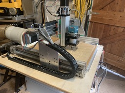
  1. Lappa

    Lappa New
    Builder

    Joined:
    Mar 28, 2019
    Messages:
    14
    Likes Received:
    6
    Lappa published a new build:

    Read more about this build...
     
  2. gary bergin

    Builder

    Joined:
    May 13, 2023
    Messages:
    17
    Likes Received:
    2
    Thank you for your post i too am in the beginning stages of my sphinx-build im building 500x500 mgn15 rail plates by Chris as well looking at the drawing for the mgn15 rail it read a total height with bearing slide at 16mm so I thought to cut my x-axis at 532 is my understanding of the size wrong or is there a reason for the 31mm thanks again
     
  3. Lappa

    Lappa New
    Builder

    Joined:
    Mar 28, 2019
    Messages:
    14
    Likes Received:
    6
    No, 532mm would be fine. If your blocks are 16mm then 532mm is the measurement to go for.
    I mounted the side plates to the linear blocks, square everything up and 631mm is what I measured. Maybe I should have been 632mm as a very slight deflection over that distance would have made the 1mm difference.
     
  4. gary bergin

    Builder

    Joined:
    May 13, 2023
    Messages:
    17
    Likes Received:
    2
    thanks for the quick response is your build completed? what spindle did you go with
     
  5. Lappa

    Lappa New
    Builder

    Joined:
    Mar 28, 2019
    Messages:
    14
    Likes Received:
    6
    I’ve been using mine for almost 12 months now. I went with a Makita RTO700 as a spindle as I had one already.
    I’ve added a few more things since the build. I built an electronic switch so I can use gcode to switch the router ON/OFF. I have added a 5.5W laser and will probably upgrade that later. I use gSender so I can software switch between the router and the laser.
    I can now control the CNC via a Bluetooth Xbox controller which is great.
    I decided to try and machine aluminium and it does it fine, using the right bits.
    I looked at adding a spindle and VFD but the spindles weigh 2.2 kg. The router works fine but you have to adjust the speed manually which really isn’t a problem
     
    #5 Lappa, Mar 12, 2024
    Last edited: Mar 12, 2024
  6. gary bergin

    Builder

    Joined:
    May 13, 2023
    Messages:
    17
    Likes Received:
    2
    so i am building mine with the intent of mostly machining small aluminum plates i ordered a "heavy duty" c beam for the x axis to aid with the weight of a spindle
     
  7. Lappa

    Lappa New
    Builder

    Joined:
    Mar 28, 2019
    Messages:
    14
    Likes Received:
    6
    I thought about that but I’d want 8 or 10mm side plates rather than the 6.4mm. I got a quote to water jet cut a set of 8mm plates before I bought the plates from Chris and it was about the same price but I needed the dxf files to get exact hole location etc. so I didn’t go ahead.
    One thing I forgot to mention is I added tension nuts and bearings to the lead screws on the X and Y lead screws. I was having problems with the inner stop collars moving which put a little freeplay in those axes. Certainly made a difference but I had to buy all new lead screws as I needed extra length for the tension nuts so that’s something to think about before ordering cutting lead screws to length.
    I will probably have to modify the Z axis to get access to the anti back lash nut adjustment. You can’t get to them when assembled.
     
  8. gary bergin

    Builder

    Joined:
    May 13, 2023
    Messages:
    17
    Likes Received:
    2
    thats very helpful thank you i will definitely look into the tension nuts was on per axis sufficient? also im not sure of what size to rails and leadscrews to order for the z axis the original sphinx uses 250mm but with chris plates being 2in taller do those dimensions change?
     
  9. Lappa

    Lappa New
    Builder

    Joined:
    Mar 28, 2019
    Messages:
    14
    Likes Received:
    6
    Edited to give correct dimensions

    Re tension nuts and thrust bearings - you need a set at each end of the lead screw. The go on the outside of the plates.
    The ones I bought consists of a brass nut ( with locking grub screw) and thrust bearing set(consists of a thrust bearing and two thrust plates).
    Re Z linear rails - I used 250mm. My plates are 11”. The X gantry sits 7.5” above the 8020 extrusion base and I use a 0.5“ base board attached to the extrusion. I then have a 17”x17”x 0.5” spoil board fixed to the base board, so in effect it’s 6.5” from spoil board to bottom of the X gantry. The 250mm linear rails gives me JUST enough down movement to use a 25mm diameter “plate” bit to flatten the spoil board because the Makita sits high (I use two mounts for rigidity). If I used one mount, I’d have plenty of height/movement all the way to the base board.. If you’re worried, go 300mm but you are not really going to gain much use of the extra length unless you are using very thin spoil boards..
     
    #9 Lappa, Mar 13, 2024
    Last edited: Mar 13, 2024
  10. Lappa

    Lappa New
    Builder

    Joined:
    Mar 28, 2019
    Messages:
    14
    Likes Received:
    6
  11. gary bergin

    Builder

    Joined:
    May 13, 2023
    Messages:
    17
    Likes Received:
    2
    Your help has been invaluable im still getting parts in im sure ill have more questions thanks again
     
  12. gary bergin

    Builder

    Joined:
    May 13, 2023
    Messages:
    17
    Likes Received:
    2
    so i got most all my parts in now and have the frame built im putting the rails on now whats the best way to get them lined up correctly i was going to use an indicator to make it straight with the extrusion and then use that rail as reference to line up the bottom rail but then realized that they could be straight but the distance could be off for the y plate to bolt to the blocks? i dont know if im over thinking it but id appreciate your input on how you did it thanks
     
  13. Lappa

    Lappa New
    Builder

    Joined:
    Mar 28, 2019
    Messages:
    14
    Likes Received:
    6
    I’m on a tour at the moment.. I should be able to reply with a detailed answer tomorrow.
     
  14. Lappa

    Lappa New
    Builder

    Joined:
    Mar 28, 2019
    Messages:
    14
    Likes Received:
    6
    I aligned a top linear rail on one side to a set distance between the top of the side C beam and the side of the linear rail and tighten the screws fully. I then attached the two top blocks to the side , tightened the block screws making sure the plates slid freely from the back to the front.
    I then attached the bottom linear rail and left the screws loose so I could move the bottom rail up and down a tiny amount.
    I the attached the two Botton blocks leaving the screws loose. I then moved the plate to the back and tighten the back linear rail screws, but not very tight. I then slide the plate to the front and tightened the two front linear rail screws, but not very tight.
    I then moved the rail to the centre and tightened the centre linear screws but not very tight.
    I then checked that the plate slid easily from to back,
    I then tightened all the screws to final tension and once again checked that the plate slides easily front to back.
    Now comes the time consuming part.
    Tighten the lower block screws, one one block, one at a time, checking after each tightening that the plate slides freely. If you tighten a screw and the rail gets hard to move, you will need to shin between the plate and the block near that screw. Continue on the block so when all the screws are tightened the plate slides freely. I found some need a shim around the top screws and others between the bottom screws. Then do the same for the other block.
    Once you have one completed side sliding freely, do the same to the other side.
    I had to do the same on the X axis.
    It took me a few hours from memory.
     
  15. gary bergin

    Builder

    Joined:
    May 13, 2023
    Messages:
    17
    Likes Received:
    2
    Thank for this detailed instruction it is a big help do you recall the size shims you used
     
  16. gary bergin

    Builder

    Joined:
    May 13, 2023
    Messages:
    17
    Likes Received:
    2
    on another note im using a controller that supports auto squaring for the y axis do ypu think its necessary for a 500x500 build?
     
  17. Lappa

    Lappa New
    Builder

    Joined:
    Mar 28, 2019
    Messages:
    14
    Likes Received:
    6
    This is the shim packet I bought
    Steel Shim Assortment 150Mm X 150Mm (4 Sizes) | Assortments - Shim Stock

    I mainly used the two smaller sizes
    I would use auto Y axis squaring if it is available I normally check mine before I start a job by homing and measuring with a vernier.
    I’d be interested in the controller your using.
    Mine is a self built unit based on an Arduino Uno board
     
  18. gary bergin

    Builder

    Joined:
    May 13, 2023
    Messages:
    17
    Likes Received:
    2
    im using the 6x controller for fluidnc ive done alot of research and back and fourth on deciding what will be best for my application and fluidnc is grbl based and provides alot of options
     
    Lappa likes this.

Share This Page

  1. This site uses cookies to help personalise content, tailor your experience and to keep you logged in if you register.
    By continuing to use this site, you are consenting to our use of cookies.
    Dismiss Notice