Welcome to Our Community

Some features disabled for guests. Register Today.

Rack and Pinion (Death to Belts)

Discussion in 'CNC Mills/Routers' started by Joe Young, Dec 9, 2018.
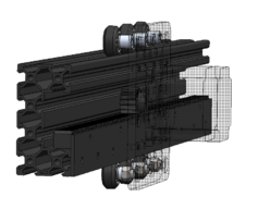
  1. Joe Young

    Joe Young New
    Builder

    Joined:
    Mar 10, 2017
    Messages:
    7
    Likes Received:
    53
    Awestruck likes this.
  2. Tracy Ranson

    Tracy Ranson Well-Known
    Builder

    Joined:
    Nov 4, 2014
    Messages:
    88
    Likes Received:
    32
    I really would like to see more of how this low profile rack and pinion could be used with the C-beam and would like to see if Openbuilds would be interested in offering an affordable rack and pinion combo. Either way I would be interested in knowing who supplies the low profile rack and pinion as this is a direction that I would like to take. I think that a helical rack and pinion would be better but if I can at least get a link to the supplier that would be great. I am not an engineer but I know that a rack and pinion set up like this could easily provide a huge improvement to the linear drive mechanics of a DIY machine, not only will it improve cutting capability but it would also greatly reduce backlash
     
    mike dauteuil likes this.
  3. Rick 2.0

    Rick 2.0 OpenBuilds Team
    Staff Member Moderator Builder Resident Builder

    Joined:
    Dec 20, 2013
    Messages:
    2,852
    Likes Received:
    1,524
    I suggest moving the rack inside the C-beam. You don't need to add extensions on the wheel spacers that way. Also teeth facing down decreases the potential for debris collecting in them.

    Rack.jpg
     
  4. Tracy Ranson

    Tracy Ranson Well-Known
    Builder

    Joined:
    Nov 4, 2014
    Messages:
    88
    Likes Received:
    32
    To reduce debris you could also add some sort of brush set up or way covers of some sort.
     
  5. Steve Mc

    Steve Mc New
    Builder

    Joined:
    Nov 21, 2016
    Messages:
    8
    Likes Received:
    4
    Really like the idea of a rack and pinion system incorporated into the Open-Builds eco-system. one thing I have noticed in other implementations is the use of a pivot and spring-tensioner for contact between the rack and pinion gear. Can anyone (out of interest) give me the reasoning for doing it that way? The only thoughts I had was to compensate for any misalignment or non-linearity.
     
  6. ChadRat6458

    Builder

    Joined:
    Dec 10, 2014
    Messages:
    93
    Likes Received:
    24
    Wow, I would be interested in this. I don't like the belts either. 8mm lead screws are not that great for long distances. 10mm lead screws would be great. Rack and pinion would be awesome.
     
  7. MCRCNC

    MCRCNC New
    Builder

    Joined:
    Jul 24, 2017
    Messages:
    6
    Likes Received:
    5
    This is cool, would be useful on larger machines as you can run as many racks as you need.
    I think the spring loading is to ensure optimum contact area with the teeth. I think I've seen you can get backlash with R&P if the gear doesn't touch both front and rear teeth, so any direction change has a minute jump between the two before engaging. I'd say the spring avoids that. The CNC router parts has a spring to pull the gear up (with teeth pointing down).
    Very interested to see where this goes.
     
  8. Joe Young

    Joe Young New
    Builder

    Joined:
    Mar 10, 2017
    Messages:
    7
    Likes Received:
    53
    Hey MCRCNC,

    Here's the solidworks pack and go of the concept. Mmcaster p/n are located in the assembly tree. Keep in mind that this is just a concept design. Following my goliath upgrades, I'll design and cut a custom plate with 6mm 6061 AL. The current carriage uses a modified C-beam plate, with some cut extrudes for holding the nema23.

    Please let me know if you make any progress before i do. Sharing is caring..
     

    Attached Files:

    Bernie CLark likes this.
  9. Joe Young

    Joe Young New
    Builder

    Joined:
    Mar 10, 2017
    Messages:
    7
    Likes Received:
    53
    I like the idea. Anything to decrease the moment load on the carriage is a win. Debris could be an issue as well, like you mentioned. The only annoyance is designing around the COTS gear rack and pinion. It gets tricky with the packaging/fasteners when you throw it on the inside. But its worth investigating..
     
  10. Joe Young

    Joe Young New
    Builder

    Joined:
    Mar 10, 2017
    Messages:
    7
    Likes Received:
    53
    The eccentric nuts and squish from the wheels could cause misalignment, or non optimal gear meshing which would lead to inaccuracies in the steps/mm or backlash. This wouldnt really be a problem with a 3d printer since theres virtually no load, but its an issue with CNCs.
     
  11. Michael.M

    Michael.M Veteran
    Staff Member Builder Resident Builder

    Joined:
    Jan 21, 2017
    Messages:
    432
    Likes Received:
    263
    Interesting concept. Looking forward to your progress.
     
  12. ymilord

    ymilord Journeyman
    Staff Member Builder Resident Builder

    Joined:
    Oct 2, 2014
    Messages:
    77
    Likes Received:
    159
  13. CNCMD

    CNCMD Journeyman
    Builder

    Joined:
    Jul 29, 2017
    Messages:
    148
    Likes Received:
    114
    Add some linear rail and forget the wheels.
     
  14. gmorse7

    gmorse7 New
    Builder

    Joined:
    Feb 20, 2017
    Messages:
    23
    Likes Received:
    6
    Would like to see this. I like the idea of placing the rack on top inside the C.
     
  15. matt_o_70

    matt_o_70 New
    Builder

    Joined:
    Dec 15, 2013
    Messages:
    54
    Likes Received:
    15
    I have no means open the file to check the McMaster PN's but I have yet to see a 4 foot (20 degree) section gear rack that is NOT $50 or more each.

    You mention a $20 gear rack - but how long is it or where is it purchased from?
     
    #15 matt_o_70, Dec 22, 2018
    Last edited: Dec 23, 2018
  16. msaeger

    msaeger New
    Builder

    Joined:
    Sep 23, 2015
    Messages:
    32
    Likes Received:
    1
    I like the idea. CNC router parts says you need a gear reduction with the rack and pinion to get good enough resolution but I see other places say you don't because you can use microstepping but then I read microstepping is bad so who knows whats really true.
     
  17. Adam Filipowicz

    Adam Filipowicz Journeyman
    Builder

    Joined:
    Dec 21, 2014
    Messages:
    259
    Likes Received:
    129
    I really like the CNC Router Parts R&R System, A gear reduction is needed, even with Microstepping, so we have the torque and resolution needed,
     
  18. Awestruck

    Awestruck New
    Builder

    Joined:
    Dec 17, 2017
    Messages:
    76
    Likes Received:
    13
    I like this idea and look forward to seeing how you move it forward.
     
  19. Adam Filipowicz

    Adam Filipowicz Journeyman
    Builder

    Joined:
    Dec 21, 2014
    Messages:
    259
    Likes Received:
    129
    Based on this design, you are using a pinion with 16 teeth/20 Pitch and a pitch diameter of 0.8" so for each rotation the Axis would move 2.513" (63.83mm) if Stepper motor was set to full steps, 1/1 = 200steps
    machine positioning accuracy is 3.13 steps per mm, or 0.319mm /step

    Compared to current 8mm Tr8*8-2p 4 Start Acme screw used, an Axis moves 8mm per rotation, if Stepper motor was set to full steps, 1/1 = 200steps
    machine positioning accuracy is 25 steps per mm, or 0.04mm / step

    We basically need a 8:1 gear reduction for this rack/pinion to match current Acme system accuracy

    Compared to the CNCRouterParts R&P Pro system they are using a pinion with 20 teeth/20 Pitch and a pitch diameter of 1" so for each rotation the Axis would move 3.141" (79.796mm) if Stepper motor was set to full steps, 1/1 = 200steps on its current 3:1 Gear reduction (ie 600 steps/roation)
    machine positioning accuracy is 7.52 steps per mm, or 0.133mm /step

    perhaps the real question is how much position accuracy is really required.
     
    #19 Adam Filipowicz, Jan 1, 2019
    Last edited: Jan 1, 2019
  20. Ianb007

    Ianb007 New
    Builder

    Joined:
    Apr 5, 2019
    Messages:
    1
    Likes Received:
    0
    Would you be able to save the Solidworks in an STEP file or version that can be opened in 2015 SW?
     
  21. Tracy Ranson

    Tracy Ranson Well-Known
    Builder

    Joined:
    Nov 4, 2014
    Messages:
    88
    Likes Received:
    32
    Could you please convert the files to DXF or DWG not everyone has Solidworks. Thanks
     
  22. Forestbird Originals

    Builder

    Joined:
    May 6, 2019
    Messages:
    19
    Likes Received:
    4
    I agree with him, which is why keeping a spring-like load on the gear side of the contact would help it to be adjusted as it wears and with any inconsistencies.
     
  23. sunil

    sunil New
    Builder

    Joined:
    Aug 16, 2016
    Messages:
    26
    Likes Received:
    11
    any progress on this idea, love to switch over to rack and pinion
     
  24. Aleks-Yash

    Builder

    Joined:
    Feb 8, 2024
    Messages:
    1
    Likes Received:
    0
    If I use such a design to lift weights, I wonder, would it be beneficial in terms of gear and rack contact, if I move the gear to the top of the slider, and place the console in the direction parallel to the slider plate? The weight momentum would put a CCW rotational force on a slider, and make the gear sit tighter on a rail on full load (to prevent backlash etc) and sit normal with no load (less wear). Or am I wrong? (would it excessively/uneven wear the slider wheels or gear or something, or maybe the effect would be negligible or the whole idea is just nonsensical).
    I can even move bottom-left and top-right rollers closer to the horizontal centerline to reduce the extra wear caused by the load.

    upload_2024-2-8_20-4-28.png
     
    #24 Aleks-Yash, Feb 8, 2024
    Last edited: Feb 8, 2024
  25. joecmay

    joecmay New
    Builder

    Joined:
    Jan 1, 2024
    Messages:
    12
    Likes Received:
    1
    Using rack and pinion on my custom build with linear rails / V rollers and guides. Started with ShopBot machine 24 years ago redesigned to handle 24 position rotary auto tool changer.
    Vac bed 4x8. Now I do it for fun at home. the nema23 1/8 step is strong enough to machine aluminum parts that you can see, side plates. I went through belts, lead screws at home ended up with what I knew worked best for me in the past. Helical rack and pinion would be the best, but is very costly.
    . 1000002895.jpg 1000002896.jpg 1000002897.jpg 1000002898.jpg 1000002899.jpg
     
    Rick 2.0 likes this.

Share This Page

  1. This site uses cookies to help personalise content, tailor your experience and to keep you logged in if you register.
    By continuing to use this site, you are consenting to our use of cookies.
    Dismiss Notice