Welcome to Our Community

Some features disabled for guests. Register Today.

Portable Sphinx 1050

Discussion in 'CNC Mills/Routers' started by jgreenwd, Oct 22, 2018.
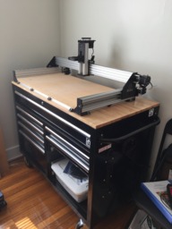
  1. jgreenwd

    jgreenwd New
    Builder

    Joined:
    May 25, 2018
    Messages:
    5
    Likes Received:
    8
    jgreenwd published a new build:

    Read more about this build...
     
  2. Mark Carew

    Mark Carew OpenBuilds Team
    Staff Member Moderator Builder Resident Builder

    Joined:
    Jun 28, 2013
    Messages:
    2,746
    Likes Received:
    2,412
    First coolest wedding present ever! Congrats brother :)
    Great looking build @jgreenwd love the use of the cabinet and how the sizing worked out for you.
    This 1050 machine is one of favs here as well because of that same reason it just fits really well on most table tops.
    Following along...Keep up the good work
    P.S. Another congrats is in order for being the 1000th Build on OpenBuilds!:thumbsup:
     
    Michael.M, jgreenwd and MaryD like this.
  3. jgreenwd

    jgreenwd New
    Builder

    Joined:
    May 25, 2018
    Messages:
    5
    Likes Received:
    8
    Thanks @Mark Carew ! I'm anxiously awaiting my wiring kit so I can continue the build!
     
    Mark Carew likes this.
  4. jgreenwd

    jgreenwd New
    Builder

    Joined:
    May 25, 2018
    Messages:
    5
    Likes Received:
    8
    Update: 12/4/18

    I've installed the wiring kit and drag chains. Everything went together very smoothly. Primarily, I followed the wiring video. I continued with my "aversion-to-spacers" theme while mounting the carriage for the 1m drag chain on the back. Instead of using the drop-in T-nuts and hanging it from the x-axis, I just used the angle brackets and hung it from x-axis motor mounts. This raised the cross-member about 5mm and increased clearance with the y-axis rails. I had to do a tiny bit of filing on the end of the cross-member, but that took less than 5 minutes to finish off.

    IMG_2794.jpg
    I mounted the xPro "upside down" to put the USB port on the right side for cable management.

    IMG_2795.jpg
     
  5. jgreenwd

    jgreenwd New
    Builder

    Joined:
    May 25, 2018
    Messages:
    5
    Likes Received:
    8
    Update: 12/4/18 Continued

    The next bit was drilling a hole through the bench top and the box top to route PSU wires. I inserted a brass bushing through the hole to keep any vibration in the cabinet from gradually sawing through the wires and making bad things happen. Also, it makes the hole look better ;) You can see the bushing on the bottom side of the fan in the photo. It's just a small brass circle in the photo.
    IMG_2798.jpg

    That set me up to mount the PSU inside the cabinet. There is sufficient space behind the drawer area thanks to the way the locking mechanism is designed.
    IMG_2797.jpg

    I will add the PSU for the spindle on the left side, beside the other.
    I will need to make sure airflow is still ok, since this will be behind 2 drawers. Worst case scenario, I have to add vent holes in the right side wall, which isn't a big deal. The area beneath those 2 drawers will still remain open. One benefit to having them enclosed in this area is not having to mess with keeping wood and metal chips away from the fans.
     
  6. jgreenwd

    jgreenwd New
    Builder

    Joined:
    May 25, 2018
    Messages:
    5
    Likes Received:
    8
    Update 12/4/18 Continued

    The last thing (which has taken a bit) was adapting the spindle mount that came with mine to fit the screw pattern on the gantry plate. The holes on the mount were predrilled for the included M7 screws. The plate is too narrow to accommodate those, so opening up the plate threads was out. I wound up machining the back of the mount flat and tapping 2 horizontal holes to line up with the plate holes. I also tapped 2 vertical holes in the bottom to use the original brackets.

    Originally, the mount is designed like a C and clamps the spindle with through-mounted machine screws. Since I couldn't use those holes for that purpose, I opted to open up the M7 holes and tapped them to accept M8's. That has worked better than I could have hoped!

    IMG_2796.jpg

    It's coming along, but I still have a bit to go!
     
    Lord Chalfont likes this.

Share This Page

  1. This site uses cookies to help personalise content, tailor your experience and to keep you logged in if you register.
    By continuing to use this site, you are consenting to our use of cookies.
    Dismiss Notice