Welcome to Our Community

Some features disabled for guests. Register Today.

Photogrammetry 3d Scanner

Discussion in '3D Scanners' started by Ticky-Tack, Jun 21, 2019.
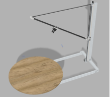
  1. Ticky-Tack

    Builder

    Joined:
    Jun 19, 2019
    Messages:
    4
    Likes Received:
    17
  2. sharmstr

    sharmstr OpenBuilds Team
    Staff Member Moderator Builder Resident Builder

    Joined:
    Mar 23, 2018
    Messages:
    2,039
    Likes Received:
    1,434
    Awesome. Really want to see where this is headed.
     
    Ticky-Tack likes this.
  3. Ticky-Tack

    Builder

    Joined:
    Jun 19, 2019
    Messages:
    4
    Likes Received:
    17
    I've went through a number of ideas, before arriving to this one. My objective was to make a high quality open sourced 3D scanner. And it started with investigating with LIDAR methods. I still intend to do LIDAR in the future, I've always wanted to play with highly sensitive Time-of-Flight circuits. But the costs are just too much for what I'm trying to achieve atm.

    For the LIDAR idea, I was going to build a circuit based off Texas Instruments TDC7201 TOF chip http://www.ti.com/lit/ds/symlink/tdc7201.pdf
    Using differential time between the two timer circuits, TI claims you can achieve sub-mm accuracy with their built-in 128 sample averaging.

    The circuitry made sense, and I could manufacture my own dev board for $30, or buy theirs for $80. Where the problem came in was with the laser and optics. The optics would require a beam splitter, and some nice quality lenses to achieve a small diameter laser dot. If I can't get the laser dot focused to a mm/sub-mm level, the TOF sampling would be useless. I'd also have to use a higher powered laser with the beam splitter in place, and for the receiving sensor to detect the defracted light reflecting off the object. Which puts the laser/optics unit itself into the $200-$300 range. Still cheaper than the majority of the LIDAR systems out there, but not really within my budget.

    My next venture was to use a DSLR, with a similar design as to the one I'm building now, just had more robust support from the top of the linear rail. But then the costs were really high with that idea, since DSLR's are heavy and bulky.

    I sacrificed the DSLR, thinking the higher resolution will not provide any added benifits for the objects I will be scanning. If I was doing full body scans of people, I can see the benifit of a DSLR, or multiple camera setups. But for the distances I'm looking at, I don't think the lower resolution will make much of a difference. It also slims up the design a lot.

    I have parts on order to make a "500mm" version of the design. The CAD designs were made for the 1000mm design. What is nice about this design, is you don't have to change much to scale. Just swap out the linear rails and V-Slots for smaller dimensions, and that's it. There maybe an upper limit to how tall you can make the scanner, and would require additional support, but that's simple, just add more V-Slots.

    Too bad we haven't invented portals yet, I want my parts to arrive now lol.
     
    GrayUK likes this.
  4. sharmstr

    sharmstr OpenBuilds Team
    Staff Member Moderator Builder Resident Builder

    Joined:
    Mar 23, 2018
    Messages:
    2,039
    Likes Received:
    1,434
  5. Ticky-Tack

    Builder

    Joined:
    Jun 19, 2019
    Messages:
    4
    Likes Received:
    17
    Some updates to the designs.
    • Turntable wheel support now sketched up
    • Slight adjustments to plastic part dimensions, mostly adding more clearance for screw holes
    • Turntable mounting spool designed
    New files have been uploaded to build page.
     
    sharmstr likes this.
  6. Ticky-Tack

    Builder

    Joined:
    Jun 19, 2019
    Messages:
    4
    Likes Received:
    17
    Well, the build process has been a lot of trial and error. There were a number of problems. But I finally have a working prototype.

    What went wrong:
    • The linear rail for the camera would not fold down with it's own weight. Had to add a linear spring to keep tension on the timing belt
    • Turntable wheel holder sucked, they broke easily. I made a new bracket, 1 stencil assembly for all 4 wheels, and more robust.
    • The timebelt bracket at the top of the linear actuator was flimsy, it broke one day causing the camera rail to swing down, slam into the turn table, and broke the hinge on the carriage. The hinge and timebelt bracket has been beefed up
    • The turntable stepper motor mount was stupid, it's hard to get reliably flat prints from plastic, just too much room for temp flexing, over extrusions, etc. Replaced with a standard metal collar for stepper motors, the turntable is now level
    • Reduced the size of the camera carriage to only have 2 linear bearings instead of 4. 4 was over kill, and again with 3d printers not being the most accurate, having 2 bearings offset from eachother by a small amount, adds a lot of friction, meaning more strain on the motors.
    • My motor drivers fried themselves, don't trust china
    • The movement of the linear rail was not what I was expecting. My imagination doesn't play by the laws of physics, but the movement still serves the purpose I need it for. Just had to write some more trig into my program
    What has been done since the last update:
    • It's alive!
    • Arduino program, and serial protocol has been written
    • Node js API server to interface with serial protocol, and provide a standard http protocol for control
    • Camera coordinate and angle translation
    • Homing
    • Scanning movement program done
    What's to come:
    • Actually start taking pictures
    • Make a UI to show and control the scanner
    • Test and debug, cause we always know that happens
    • Polish CAD designs, all of my new parts are in the CAD design locally, just they aren't placed correctly, and don't have screws, washers, etc placed


  7. sharmstr

    sharmstr OpenBuilds Team
    Staff Member Moderator Builder Resident Builder

    Joined:
    Mar 23, 2018
    Messages:
    2,039
    Likes Received:
    1,434
  8. Rob Taylor

    Rob Taylor Master
    Builder

    Joined:
    Dec 15, 2013
    Messages:
    1,470
    Likes Received:
    746
    Looks great! I want a photogrammetry setup, but unfortunately it would likely be primarily for people, which for all practical intents and purposes means the hundreds-of-DSLRs-on-a-cage method. Even at ~$200 a camera, that racks up real quick!

    A really nice hand-held laser unit at affordable (ie. not $100k) prices would be pretty handy too though. A couple times a month I wish I had one!

    It's fun to do, anyway. This was a park bench I shot a couple years ago:

    benchHQlossy.gif

    Some fairly standard photogrammetry precautions and PhotoScan made very short work of it, it was really easy. It's sitting on a quick Substance Bitmap2Material floor underneath the vignette of ground.

    Not sure how valuable this method is in terms of actual calibrate-able measurements though, unfortunately.
     
  9. ozzy66

    ozzy66 New
    Builder

    Joined:
    Jan 22, 2023
    Messages:
    3
    Likes Received:
    0
    The two primary methods for digital 3D modeling are 3D scanning and photogrammetry.
    I am doing 3D modeling myself but I need 3d scanning services for my model should I go for any company or buy a scanner myself?
     
  10. Mark Carew

    Mark Carew OpenBuilds Team
    Staff Member Moderator Builder Resident Builder

    Joined:
    Jun 28, 2013
    Messages:
    2,746
    Likes Received:
    2,412
    I like to have the control over the outcome of a project so in my opinion, I would always do it myself to gain the results I am after.
     

Share This Page

  1. This site uses cookies to help personalise content, tailor your experience and to keep you logged in if you register.
    By continuing to use this site, you are consenting to our use of cookies.
    Dismiss Notice