Welcome to Our Community

Some features disabled for guests. Register Today.

LR/BS CNC Router

Discussion in 'CNC Mills/Routers' started by Ptiwee, Apr 26, 2020.
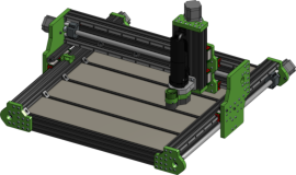
  1. Ptiwee

    Ptiwee New
    Builder

    Joined:
    Oct 27, 2016
    Messages:
    14
    Likes Received:
    21
    Ptiwee published a new build:

    Read more about this build...
     
  2. Joe Santarsiero

    Joe Santarsiero OB addict
    Staff Member Moderator Builder

    Joined:
    Oct 30, 2014
    Messages:
    902
    Likes Received:
    196
    Very nice. Will you be worried about the z-axis dropping when the motor is powered down?
    You could get more travel if you flipped the side the couplings are on, but it wouldn't look as clean.
    I think it would look better if the Y motors were off to the back of the machine. That's no big deal though.
     
  3. Ptiwee

    Ptiwee New
    Builder

    Joined:
    Oct 27, 2016
    Messages:
    14
    Likes Received:
    21
    Does it happens with ballscrews ? Or is it related to weight ? I've been working with ACME screws on CNC and 3D printers and never faced this problem.

    I think this will require a second plate to fix the X-Axis rails to the V-Slots, am I wrong ?


    I put them on the front otherwise the Y-Axis will be outside of the frame, so I'll be losing some precious centimeters (I'm storing the machine in my appartement, small footprint is important to me).
     
  4. Joe Santarsiero

    Joe Santarsiero OB addict
    Staff Member Moderator Builder

    Joined:
    Oct 30, 2014
    Messages:
    902
    Likes Received:
    196
    Yeah. Their friction is really low compared to ACME. ACME self lock. It is related to the weight it takes to overcome static friction.
    I'm not sure how the hobby scene is doing it, but there is usually a DC brake.
    You could just build it and put a wood block under the Z when the machine is off. :)

    I don't think it would. It looks pretty tight in there, but you might be able to get the screw encapsulation in the gantry arm and use the standoff plate to mount the motor to.

    Ohh. yep. I see can see that now. duh
     
  5. Ptiwee

    Ptiwee New
    Builder

    Joined:
    Oct 27, 2016
    Messages:
    14
    Likes Received:
    21
    Thanks for your advice. Regarding the Z-Axis dropping, I added a little stand on the X plate where the Z-Axis can go resting outside of the work area.
    It allows me to implement a macro to go there, which should be more practical than the block.

    Stand-off.png
    Stand-off (2).png
     
  6. Joe Santarsiero

    Joe Santarsiero OB addict
    Staff Member Moderator Builder

    Joined:
    Oct 30, 2014
    Messages:
    902
    Likes Received:
    196
    That's a really nice idea if it does drop.
     
  7. Woodsmith

    Woodsmith New
    Builder

    Joined:
    May 1, 2020
    Messages:
    8
    Likes Received:
    4
    Nice clean design, and just the design methodology I am interested in for building a machine too. With cheaper sources of profiled linear rails and ballscrews now available it makes sense to use the correct components to give a robust, low maintenance machine.

    It seems a little ironic to be using V- slot, (developed for wheel based linear motion) for mounting profile rails. Is there a reason to still use V-slot over T-slot?

    Only other observation is that whilst 1605 ballscrews seem common on metal cutting machines, 1610 seems more common for wood cutting ones (you want the greater speed)

    Please share more of the design and the thinking behind your decisions.

    Thanks
     
    #7 Woodsmith, May 1, 2020
    Last edited: May 1, 2020
  8. Yosmany325

    Builder

    Joined:
    Jan 25, 2020
    Messages:
    2
    Likes Received:
    0
    Very nice work. I'm currently working in a design similar to this regarding the use of linear rails and ball screws. In my particular case, I don't have access neither to V-Slot nor T-Slots and I'm planning to use rectangular aluminum tube of 70x45x3mm. I will try to upload my ideas soon. Keep going and good luck.
     
  9. Ptiwee

    Ptiwee New
    Builder

    Joined:
    Oct 27, 2016
    Messages:
    14
    Likes Received:
    21
    You're right, I'm using V-slots as they are easier for me to source (1 command on Ooznest and I can get all the components), actually any aluminium extrusion could do the job. T-slot should be even better as the contact surface with the rail will be larger.

    Indeed, once again SFU1605 are easier to find, but there is no constraint in the design not to switch to 1610.

    I will share the DXF for the plates as soon as I validate the design. I am now searching the right settings in order to cut the plates on my OX CNC.
     
  10. Ptiwee

    Ptiwee New
    Builder

    Joined:
    Oct 27, 2016
    Messages:
    14
    Likes Received:
    21
    Hello, during the week I beefed up the design for more rigidity.

    MGN-15 rails have been replaced with HGR-15. The linear actuator have been reinforced with corner angles. They are now made of 1 20x80 V-Slot and 2 20x40 V-Slots. Aluminium plates have been thicken to 15mm. FK12/FF12 blocks have been replaced for BK12/BF12 which allows for bigger work area.

    I should order the material very soon. I think the first implementation will be made out of MDF to confirm that everything aligns properly. I may keep it like this for a while if it works properly ...
     
  11. Joe Santarsiero

    Joe Santarsiero OB addict
    Staff Member Moderator Builder

    Joined:
    Oct 30, 2014
    Messages:
    902
    Likes Received:
    196
    You're going to have very good alignment on the ball screw to stepper shafts. You could probably switch to solid couplings and tighten the motors after the ball screws have been installed. I've had those aluminum couplings twist up from too much torque and seen some break from fatigue.

    Run some math to spec out the right size carriages without over spending.
     
  12. Ptiwee

    Ptiwee New
    Builder

    Joined:
    Oct 27, 2016
    Messages:
    14
    Likes Received:
    21
    That's definitely an easy and cheap update. Actually I put the flexible couplers because they are available in the OpenBuilds library on my CAD software ...

    I cannot run those maths as I don't know of any formula ... I don't know wether they can be easily understood or a full mechanical engineer training is needed :/
     
  13. Joe Santarsiero

    Joe Santarsiero OB addict
    Staff Member Moderator Builder

    Joined:
    Oct 30, 2014
    Messages:
    902
    Likes Received:
    196
    Downloads - Huntley, Illinois- HIWIN Corporation

    Linear Guideways PDF Starting on pg.6 of the pdf.
     
  14. Ptiwee

    Ptiwee New
    Builder

    Joined:
    Oct 27, 2016
    Messages:
    14
    Likes Received:
    21
    Thank you for your precious help. I haven't quite yet understood all of the formulas, yet the documentation has been precious.
    My biggest concern was regarding the side rails being vertical and not horizontal, but according to the documentation the loads are equivalent.
    I ordered the pieces recently and am waiting for everything to arrive.
    I started 3D printing the plates as I sold my OX CNC before changing the design ... The 15mm thick plastic seems quite robust and should be sufficient in order to cut the plates out of aluminium, as only the drill needs to be precise.

    I'll keep you updates once the parts are ready. Definitely alignment will be a challenge ...
     
  15. Joe Santarsiero

    Joe Santarsiero OB addict
    Staff Member Moderator Builder

    Joined:
    Oct 30, 2014
    Messages:
    902
    Likes Received:
    196
    Yes. Most profile rails are very sturdy in all loading situations. If you spend some good time working through the math you can come to a decent conclusion as to what will be sufficient and what will be overkill for the loads they will see while in use. Light, rigid, and least expense to get the job done are the goals.
    If you need some help interpreting the math then ask around. Kahn Academy is also a great source to brush up on math skills.

    If you plan your 3d prints correctly to mirror important errors and your printer is reliable then you shouldn't have many alignment issues. If you want, you can mill the new plates, install them and mill them a second time to reduce errors a little from the 3d printed parts. I suggest that when you print initially you try to butterfly them in pairs. For instance, the left screw drive plates are butterfly'd open with the insides facing up and then the right screw drive plates with the right facing up and opposite to the left plates. Same when you remill a new set of plates. ehhh. That's tough to explain here. I'm sure it'll work out for ya regardless.
     
  16. Ptiwee

    Ptiwee New
    Builder

    Joined:
    Oct 27, 2016
    Messages:
    14
    Likes Received:
    21
    Unfortunately I have more money than time ...The issue is not about the maths but more about the variables. I have no idea about the forces that would be applied.

    I'm quite confident with my Prusa doing a correct job. Let's see if I got you correctly, I should print them as follow :

    Y-Axis Plates.png

    Because I don't really like long prints, I'll go with the second solution. After some tests it seems better to have the inside facing down as the surface is a bit flatter. Also to avoid warping on such big pieces I print them without top/bottom layers, letting the infill pattern being exposed, this pattern being triangles.

    It'll look something like this :

    Capture du 2020-05-29 10-40-19.png

    For sure this will flex, but I hope the 15mm thickness will be enough to hold the machine while cutting the real plates.
     
  17. Joe Santarsiero

    Joe Santarsiero OB addict
    Staff Member Moderator Builder

    Joined:
    Oct 30, 2014
    Messages:
    902
    Likes Received:
    196
    I think you'll be alright.

    Prusa makes a great printer.

    This might be a good idea. Let us know how it works out. You really only need them to cut new plates anyways.

    You could hold them together to see how well they line up with each other.
     
  18. Corey Corbin

    Corey Corbin Well-Known
    Builder

    Joined:
    Feb 27, 2016
    Messages:
    135
    Likes Received:
    62
    I 3D printed almost all of the plates for my sphinx cnc except the right and left uprights to the X axis. 3d printing the plates make a great drill guide for the drill press. I taped the printed parts on to the aluminum plate drilled the holes. Then got a 10" nonferrous cutting blade for my table saw and cut plates out.
     
    Joe Santarsiero likes this.
  19. Ptiwee

    Ptiwee New
    Builder

    Joined:
    Oct 27, 2016
    Messages:
    14
    Likes Received:
    21
    Hi everyone,

    It's been a while but the project is not dead, the parts took quite a long time to arrive from China.
    I eventually assembled the machine last week, and do some tiny modifications (regarding the Z axis for easiest mount). Here's a picture of the machine assembled :
    IMG_20200903_211856_01.jpg

    Some features are still missing before the first cut (I need to retrieve some wood for the waste board). I am quite satisfied with the 3D printed part, yet the side panels are a bit too weak and the z axis wobble a bit if I force by hand. I created a new design to reinforce the part, I will give you the feedback once I receive the parts :
    X-Axis.png
     
    #19 Ptiwee, Sep 15, 2020
    Last edited: Sep 16, 2020
  20. Jacob Erickson

    Builder

    Joined:
    Nov 30, 2020
    Messages:
    2
    Likes Received:
    0
    Looks really good! I was wondering if you would be willing to post or send me the model you've been using. I bought parts to build a similar design using HGR20 rails but the original design has flaws. I was hoping to modify your existing design to use the rails and aluminum I've already bought.

    I was also wondering what the slots were for on the motor side plates
     
    #20 Jacob Erickson, Dec 19, 2020
    Last edited: Dec 19, 2020
  21. Ptiwee

    Ptiwee New
    Builder

    Joined:
    Oct 27, 2016
    Messages:
    14
    Likes Received:
    21
    Hi Jacob,

    DXF are already available in Files and Drawing, which format would you need ?
    Which slots are you talking about ? If you're talking about the aluminum standoffs, the motors are offset in order to use standard size linear rails and ball screw. Also it turns out that if printed with flexible materials, they make great dampers to reduce the vibrations :rolleyes:
     
  22. Jacob Erickson

    Builder

    Joined:
    Nov 30, 2020
    Messages:
    2
    Likes Received:
    0
    The DXF was really useful for the plates! I was able to minimally modify yours in order to mount the larger rails. The slot I was curious about is pictured below.

    I was hoping for a copy of the whole assembly. I've been trying to figure out how to modify the Z axis to use the parts I have on hand.

    upload_2020-12-29_16-3-27.png
     
  23. Ptiwee

    Ptiwee New
    Builder

    Joined:
    Oct 27, 2016
    Messages:
    14
    Likes Received:
    21
    Ok, I published the STEP file, the export might not be perfect but I hope it helps.

    Regarding the slot, it is meant to pass the endstop cable, as shown in the picture.
    X-Axis.png
     
  24. Mostafa Hassani

    Builder

    Joined:
    Feb 15, 2021
    Messages:
    4
    Likes Received:
    0
    Very nice job. I am really interested to build one by myself. Could you please give me an approximation of cost? And do you think that this machine will be able to milling on metal (like as Aluminum or steel)?
    Thanks
     
  25. Ptiwee

    Ptiwee New
    Builder

    Joined:
    Oct 27, 2016
    Messages:
    14
    Likes Received:
    21
    Hi Mostafa,

    The cost is around 1000€ for the structure and the electronic (without the spindle), for a 750x750mm machine (~550x500 work area).

    I tried to cut aluminium with it, for sure the machine is sturdy enough but I think I don't have the proper federates/tools to achieve perfect results. You can look at the pictures, if you want me to perform any test let me know.
     

    Attached Files:

    Mostafa Hassani likes this.
  26. Mostafa Hassani

    Builder

    Joined:
    Feb 15, 2021
    Messages:
    4
    Likes Received:
    0
    Thanks a lot Pitwee
    Actually I have ordered all parts based on my little modifications on your design. I have a question.

    - What is the type of controller you are using?
    - What is the maximum torque of step motors ?

    Thanks
     
  27. Ptiwee

    Ptiwee New
    Builder

    Joined:
    Oct 27, 2016
    Messages:
    14
    Likes Received:
    21
    I'm using an Arduino with a CNC shield (like this one Kit CNC Shield + 4 Drivers DRV8825), but this is not robust for such a machine (The current limitation of DRV8825 is quite low, and it happens quite frequently that a connector would burn :().
    I might upgrade it for a Gradus (Gradus M1 PRO GRBL CNC Controller), which has the same architecture with more robust components.
    Otherwise most people would go for a Duet or a XPro, but I find those quite expensive with a lot of useless features for me.

    Regarding the motors I use those : E Series Nema 23 Stepper Motor Bipolar 1.8deg 1.26 Nm(178.04oz.in) 2.8A 57x57x56mm 4 Wires
    The torque is quite powerful, but the motors would stall above 2000mm/min, I expect more powerful motors to go faster.
     
  28. Mostafa Hassani

    Builder

    Joined:
    Feb 15, 2021
    Messages:
    4
    Likes Received:
    0
    Perfect,

    Actually , I ordered this step motor set including One out break board. but I don't know if this board is working as controller .

    https://www.aliexpress.com/item/1005002110427641.html?spm=a2g0o.productlist.0.0.67d6f000Pvo9uR&algo_pvid=4c4f787e-d05d-4ca3-b26d-1794deefdc8a&algo_expid=4c4f787e-d05d-4ca3-b26d-1794deefdc8a-26&btsid=0bb0623116161750963154008e6321&ws_ab_test=searchweb0_0,searchweb201602_,searchweb201603_

    I think if we use the controller board as you mentioned in your message, we don't need to use the drivers of step motor, is it? (I am really null in electric and control :) )

    Thanks
     
  29. Ptiwee

    Ptiwee New
    Builder

    Joined:
    Oct 27, 2016
    Messages:
    14
    Likes Received:
    21
    The controller board I suggested is using stepper drivers, they are just smaller (DRV8825).
    The one you choose deliver higher current, allowing them to drive bigger motors (Like the one you choose).

    Your controller board should embed Mach3 controller, I'm using GRBL and never used Mach3, but it should do the job :)

    Out of curiosity, what are the small modifications you made on the design ?
     
  30. Mostafa Hassani

    Builder

    Joined:
    Feb 15, 2021
    Messages:
    4
    Likes Received:
    0
    Actually there are no big modification. Just in working bed, I am gonna to use aluminum extrusion 180 mm width. And another modification is about the material of mounting plates. I want to use aluminum.

    What you think about that?
    upload_2021-3-22_21-38-52.png

    upload_2021-3-22_21-42-15.png
     

Share This Page

  1. This site uses cookies to help personalise content, tailor your experience and to keep you logged in if you register.
    By continuing to use this site, you are consenting to our use of cookies.
    Dismiss Notice