Welcome to Our Community

Some features disabled for guests. Register Today.

Lead Screw Driven Ox Derivative (850x1500)

Discussion in 'CNC Mills/Routers' started by Giarc, Mar 23, 2016.
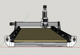
  1. Giarc

    Giarc OpenBuilds Team
    Staff Member Moderator Builder Resident Builder

    Joined:
    Jan 24, 2015
    Messages:
    2,892
    Likes Received:
    1,609
    Giarc published a new build:

    Read more about this build...
     
    Tom Allen and GrayUK like this.
  2. Giarc

    Giarc OpenBuilds Team
    Staff Member Moderator Builder Resident Builder

    Joined:
    Jan 24, 2015
    Messages:
    2,892
    Likes Received:
    1,609
    Now if only I could come up with a better name...
     
  3. Mark Carew

    Mark Carew OpenBuilds Team
    Staff Member Moderator Builder Resident Builder

    Joined:
    Jun 28, 2013
    Messages:
    2,741
    Likes Received:
    2,407
    @Giarc you have done an amazing job on this build! Thank you for the great pictures and build notes. Enjoying following along :thumbsup:
    Mark
     
  4. Giarc

    Giarc OpenBuilds Team
    Staff Member Moderator Builder Resident Builder

    Joined:
    Jan 24, 2015
    Messages:
    2,892
    Likes Received:
    1,609
    Thank you for making the parts available and for all the great ideas by everyone on this forum. I hope to get back to work on it this weekend.
     
    Mark Carew likes this.
  5. Giarc

    Giarc OpenBuilds Team
    Staff Member Moderator Builder Resident Builder

    Joined:
    Jan 24, 2015
    Messages:
    2,892
    Likes Received:
    1,609
    I built a torsion box table top (1520mm x 900mm)to mount the cnc router on. I recycled the 3/4 particle board from the sides of some old kitchen cabinets for the framing. The flattest place I could find to build on was the floor in the house. Luckily I had a bunch of large landscape tiles around (I haven't had a chance to install them yet) to pile on top for weight while the glue dried.

    [​IMG]
    Then, I added about 200 more pounds for a little while.
    [​IMG]
    I put the finished torsion box on the table saw temporarily. Man was this thing heavy. Sadly, there is a 1 mm dip in the middle over the 1520 mm length along one side. The other side it is barely noticeable. I guess my floor wasn't as flat as I hoped. I figure if the crown is up, after the framing and spoil board is installed I can surface the whole thing to true it up.
    [​IMG]
     
    GrayUK and Tom Allen like this.
  6. Serge E.

    Serge E. Journeyman
    Builder

    Joined:
    May 6, 2014
    Messages:
    730
    Likes Received:
    251
    Nice ... you really like a challenge, cutting the plates by hand. :thumbsup: Where there is a will, there's a way, eh ?
     
  7. Giarc

    Giarc OpenBuilds Team
    Staff Member Moderator Builder Resident Builder

    Joined:
    Jan 24, 2015
    Messages:
    2,892
    Likes Received:
    1,609
    Yup. I couldn't find anyone nearby to do it, so I figured I would give it a shot. So far everything is looking square so I hope it works.
     
  8. Giarc

    Giarc OpenBuilds Team
    Staff Member Moderator Builder Resident Builder

    Joined:
    Jan 24, 2015
    Messages:
    2,892
    Likes Received:
    1,609
    Well, I updated the build with lots of pictures today. Also, last night I took the "trouble shoot" gcode file posted here: Tinyg configuration and tested my newly almost completed build. All I have at this time is a few 1/4 router bits. I purchased a bunch of smaller 1/8 inch bits, but I just ordered 1/8, 3/16/, and 1/4 precision collets a few minutes ago. Elaire Corporation Here is the test cut with an old v-bit. I had the spindle speed all the way up which I think was way to fast so I burned the wood a bit on that last star.


    Now I just need to make a box for all the electronics. Any one have a design they like?
     
    Mark Carew and snokid like this.
  9. Julius

    Julius Well-Known
    Builder

    Joined:
    Nov 13, 2015
    Messages:
    193
    Likes Received:
    61
    You can cut much faster then that! Spindle speed should always be as low as possible, only up it if during a job it's being bogged down and needs the extra cutting action.
     
  10. Giarc

    Giarc OpenBuilds Team
    Staff Member Moderator Builder Resident Builder

    Joined:
    Jan 24, 2015
    Messages:
    2,892
    Likes Received:
    1,609
    Thanks for the tips. I had it turned down low ( I think 8000 rpms on the Makita). As for cutting faster, I just used the existing Gcode that I downloaded and did not modify it in any way. My dad wanted to see how it worked when he was over so I just grabbed something easy.

    Now to start on the power supply box. I went a little overkill size-wise for an arduino and DRV8825 controller/driver combo, but I may upgrade to the Openbuilds drivers. Plus, at $19.99, this was cheaper than any box I could find and it came with fans and built in usb "in" ports so I do not need to buy or fabricate that. Amazon.com: Rosewill Micro ATX Mini Tower Computer Case SRM-01: Computers & Accessories

    [​IMG]
     
    GrayUK likes this.
  11. Giarc

    Giarc OpenBuilds Team
    Staff Member Moderator Builder Resident Builder

    Joined:
    Jan 24, 2015
    Messages:
    2,892
    Likes Received:
    1,609
    I put this in the "motors" forum, but thought I would throw it in here, too:

    I am baffled. My Z-stepper, upon completing a move up, rotates counterclockwise about 2 degrees-ish. Upon moving down, when it stops, it rotates clockwise about 2 degrees-ish. I tried swapping it to another driver, and it did the same thing. It appears that all the wiring is secure and proper. It is a NEMA 23 175 oz. I have not had issues with any other motor
     
  12. David the swarfer

    David the swarfer OpenBuilds Team
    Staff Member Moderator Builder Resident Builder

    Joined:
    Aug 6, 2013
    Messages:
    3,219
    Likes Received:
    1,813
    I asked a bunch of questions in the other thread but some are answered here...
    Check setting
    $3pm Power management mode 0=motor disabled, 1=motor always on, 2=motor on when in cycle, 3=motor on only when moving

    When the motor is not powered you can feel that it clicks to 200 positions as you turn it. Micro stepping makes it stop between those magnetic clicks and if the driver is disabled at that point the motor will jump to the next click by itself.

    So all your axes need to be set to '1' = motor always on. Or '2' and set the timeout.
    More info here
    Power Management · synthetos/TinyG Wiki · GitHub
     
    #12 David the swarfer, Jul 24, 2016
    Last edited: Jul 24, 2016
  13. Giarc

    Giarc OpenBuilds Team
    Staff Member Moderator Builder Resident Builder

    Joined:
    Jan 24, 2015
    Messages:
    2,892
    Likes Received:
    1,609
    Thank you very much. I never noticed it until I had the router installed, but then again, I never really paid attention until I was cutting something and the router dropped back down and made a cut it shouldn't have made.
     
  14. Giarc

    Giarc OpenBuilds Team
    Staff Member Moderator Builder Resident Builder

    Joined:
    Jan 24, 2015
    Messages:
    2,892
    Likes Received:
    1,609
    David the swarfer likes this.
  15. Giarc

    Giarc OpenBuilds Team
    Staff Member Moderator Builder Resident Builder

    Joined:
    Jan 24, 2015
    Messages:
    2,892
    Likes Received:
    1,609
    Ok, so I didn't get much done on making my new electronics enclosure, but I did get the grid of holes drilled and countersunk to attach the top layer of particle board to the bottom layer. Due to the low level of my table top, I had to order a couple extra long end mills to drill these holes from Kodiak Cutting Tools. Then, I made another grid of larger holes because I am making different spoiler boards that will be attached to the table top by 1/4-20 screws and a grid of these E-Z lock inserts. E-Z Lok Threaded Insert, Brass, Knife Thread, 1/4"-20 Internal Threads, 0.500" Length (Pack of 25): Helical Threaded Inserts: Amazon.com: Industrial & Scientific
    [​IMG]
    I mounted the E-Z lock inserts prior to facing because I figured that there would be a slight raising around each hole after inserting them.

    Here is a quick video


    After this was all done, I carved a prize plaque for a little kayak Salmon fishing competition some friends and I do out at Dismal Nitch in August (the name indicates Lewis and Clark were a little sick of camping in the rain by the time they got out here). It is near the mouth of the Columbia River. I grabbed a couple pieces of clipart from the web, combined them in the Gimp, traced the Bitmap in Inkscape, then carved it with F-engrave. Free, free, and more free! My only regret was using oak because the grain messes with the image. The winner caught a 31 pound salmon. Good times and good eats.
    [​IMG]
    [​IMG]

    I did learn that I really need to make a dust shoe. But, back to the electronics. I have been using an Arduino and DRV8825 drivers, but I have some larger drivers I purchased a while back and I am thinking of switching. I have an Arduino Screw Shield and I was going to add capacitors to the limit switches (as discussed in other threads) to help with noise issues. I drew this up real quick and I am pretty sure I have it right, but I thought I would run it by you all real quick. I only did the z-axis and limit switch. It is similar to what @Kyo has done. Comments?
    [​IMG]
    * edit: The little green rectangles I drew on the screw shield are screw terminals I will solder on.
     
    #15 Giarc, Aug 22, 2016
    Last edited: Jan 17, 2017
    snokid, Moag and Mark Carew like this.
  16. Giarc

    Giarc OpenBuilds Team
    Staff Member Moderator Builder Resident Builder

    Joined:
    Jan 24, 2015
    Messages:
    2,892
    Likes Received:
    1,609
    I got a little more done today. I soldered on the additional screw terminals to the screw shield As pictured on the previous post. The top looks decent, but the bottom is not as pretty. However there is continuity throughout all the grounds. [​IMG]
    [​IMG]

    Now I just need to track down some .47 uf capacitors.
     
  17. Giarc

    Giarc OpenBuilds Team
    Staff Member Moderator Builder Resident Builder

    Joined:
    Jan 24, 2015
    Messages:
    2,892
    Likes Received:
    1,609
    I swung by Frye's today and grabbed some .47 uf capacitors. Rather than soldering them to the board, I removed some pin headers from an Arduino board I damaged, soldered that to the screw shield and connected it to ground. Then I installed the capacitors to the ground pin headers and their respective limit switch pin header.
    [​IMG]

    The Arduino board was my original one I used to run the CNC, but I stepped on the computer cable and damaged the plug. It could no longer connect to the computer. I had a moment of panic because I had never saved my GRBL Panel settings. :eek: Then I had a minor stroke of genius (for me). I pulled the IC off the damaged Arduino and put it on another one. All my settings were fine, so I immediately took screen shots and saved them.
     
  18. Giarc

    Giarc OpenBuilds Team
    Staff Member Moderator Builder Resident Builder

    Joined:
    Jan 24, 2015
    Messages:
    2,892
    Likes Received:
    1,609
    I got all the wiring done and have all the electronics in the enclosure so, I decided to actually try to make something. After installing a grid of these E-Z loks on the waste board for clamps I made a z probe and some clamp bases out of a cutting board.
    [​IMG]
    Z probe base and clamp cuts held down by an improvised clamp.
    [​IMG]
    I flipped the probe base over and held it in its original place using a screw in the middle and the existing tabs so I could do the bottom profile
    [​IMG]
    Then I milled the 2mm thick aluminum plate that fits in the top recess. I wired it up using an old car cell charger wire and an old headphone jack. Since I am using a computer case with a headphone jack, I used those existing wires inside from the jack as the z-probe wires to the arduino board. I did the same with the USB wires. If I do hold and resume buttons, I will use the existing computer tower power and reset switches, as well. The stains on the waste board are from the olive oil I used to lube the cutter while cutting the aluminum. It was readily available. :thumbsup:
    [​IMG]
    [​IMG]
    Z probe in action:
     
    Joe Santarsiero, GrayUK and snokid like this.
  19. pitzerwm

    pitzerwm New
    Builder

    Joined:
    Sep 10, 2016
    Messages:
    20
    Likes Received:
    1
    Very nice for sure. Do you happen to be using Bcnc? If so, what are you putting in the blank spots in the Probe tab? I have the probe as you do but my plate is just a pcb piece. It works fine, except, I can't figure out how to input the plate thickness. Hopefully, you have my answer. I started a thread on the BCNC forum but so far no answers.

    Thanks
     
  20. David the swarfer

    David the swarfer OpenBuilds Team
    Staff Member Moderator Builder Resident Builder

    Joined:
    Aug 6, 2013
    Messages:
    3,219
    Likes Received:
    1,813
    just googled it and read a couple of pages, then ran bCNC and nosed around.
    I conclude that you add the thickness of your probe plate in the 'Calibration' field.
     
  21. pitzerwm

    pitzerwm New
    Builder

    Joined:
    Sep 10, 2016
    Messages:
    20
    Likes Received:
    1
    Sorry to not figure this out, but where is the calibration field?[​IMG]
     
  22. Giarc

    Giarc OpenBuilds Team
    Staff Member Moderator Builder Resident Builder

    Joined:
    Jan 24, 2015
    Messages:
    2,892
    Likes Received:
    1,609
    I use GRBL Panel and just followed this tutorial/video CNC xPRO Driver. By snokid.
     
  23. Anthony Bolgar

    Anthony Bolgar Journeyman
    Builder

    Joined:
    Jan 14, 2016
    Messages:
    354
    Likes Received:
    198
    I am completely amazed at the quality of this build using the limited amount of tools you had. Great job!!!!!
     
  24. Giarc

    Giarc OpenBuilds Team
    Staff Member Moderator Builder Resident Builder

    Joined:
    Jan 24, 2015
    Messages:
    2,892
    Likes Received:
    1,609
    Thanks for the kind words. It was a lot of fun figuring out how to best do it with the tools I had.
     
    #24 Giarc, Oct 20, 2016
    Last edited: Oct 20, 2016
  25. semperfikurt

    Builder

    Joined:
    Jul 11, 2015
    Messages:
    22
    Likes Received:
    51
    What has your experience been like using the 1/2" acme screws? The belts are the weakest part of my machine by far and i am considering modifying mine to run those same screws from mcmaster carr. Im trying to get a sense of what it can plow through material wise with the better mechanical linkage and what that does to rapid speeds and such before getting resonance and whipping issues. Whats your mileage been like with these?
     
  26. Giarc

    Giarc OpenBuilds Team
    Staff Member Moderator Builder Resident Builder

    Joined:
    Jan 24, 2015
    Messages:
    2,892
    Likes Received:
    1,609
    I have not had any resonance or whipping issues. I easily cut plywood and particle board, plus engrave in oak and other hardwoods at 2500 mm/minute with the Makita router on the lowest setting (allegedly 10000 rpm). However, I don't know if it ever gets up that fast before it changes a direction since most of the stuff I have used it for has been small.

    I surfaced my spoiler board at somewhere between 4000-6000 mm/min taking about 1 mm off and it had no problems. The fastest I have ever sent it was 8000 mm/min (for fun), but again, I don't know If it ever got up that fast before it started slowing down. At 29 seconds in the "Drilling and Facing" video above you can see it is cutting relatively fast while surfacing a 670mm by 1275 mm area. I noticed it took about 14 seconds to go the 1275 mm so that would average about 5000 mm/min if I did the math right. But... I suck at math.

    I also checked its accuracy about a month a go. I have never calibrated it and so I thought maybe I should see if it needs it. I started the V bit at 10 mm and sent it a thousand up the Y axis. Results:

    [​IMG]

    So, I am happy with the screws thus far. It also cuts aluminum fairly well (one reason I went with screws). I cut some plates for my eggbot build and the holes and slots were workable, but a little tight, but I noticed afterwards, my end mill was not quite 1/8 inch. It was a cheap Chinese 10 pack of endmills so I can't expect perfection. I assume this was the reason for the tightness since the machine thought it had a slightly larger endmill. I am now going to measure prior to cutting if it is a critical cut.
     
    Serge E. and Moag like this.
  27. Giarc

    Giarc OpenBuilds Team
    Staff Member Moderator Builder Resident Builder

    Joined:
    Jan 24, 2015
    Messages:
    2,892
    Likes Received:
    1,609
    If you want me to try a feed/speed/depth test, send me some settings and I will give it a shot. I have never been in too much of a hurry, so I think the deepest cuts I have taken with either a 1/4 inch or 1/8 inch end mill has been about 1/4 inch and that was in plywood. I mostly have used it for engraving. I guess I did cut through 1 inch of foam in one pass, but that doesn't count.;)
     
  28. Serge E.

    Serge E. Journeyman
    Builder

    Joined:
    May 6, 2014
    Messages:
    730
    Likes Received:
    251
    The ones I get from China often turn out to be metric (3mm) even if described as being 1/8" (3.175mm). But for about 1$ an end mill, much safer for my budget to climb the learning curve. Precision seems ok as their cutting life, for what I do to date. Just need to specify 3 mm for generating traces and g-code.

    I have a few brand name mills, but yet to try them ... no need to date. Kind of scared to damage them at the price paid when wholesale mills from China are doing just fine. As you say, just need to double check their dimension prior to using.

    Used a 10$ China wholesale surfacing bit to smooth out worksurface (make parallel to gantry) and, more recently, surface a solid oak slab... works real good. Looking at some of the name brands, all triple or more the cost, wondering if they are worth the extra cost. Those with the inserts are even more expensive !
     
  29. semperfikurt

    Builder

    Joined:
    Jul 11, 2015
    Messages:
    22
    Likes Received:
    51

    Ok gotcha. I did all the math a bit ago to figure out what rapids and such the setup I was shooting for was capable of before starting to resonate but I forget what it came out to, I think it was somewhere in the 300 in/min range. Right now my machine is at 500/min for rapid but really there's no reason to run it like that other than it's just really fun!

    Did you get the flange mounted bearings for your acme screws on mcmaster carr as well? I was checking through some of that, but there were way more than I knew what to make sense of. I have seen several setups with leadscrews but wasn't sure where everyone was sourcing their components from. CNCrouterparts.com makes what looks like really high quality components but the price starts stacking up.
     
    Joe Santarsiero likes this.
  30. Giarc

    Giarc OpenBuilds Team
    Staff Member Moderator Builder Resident Builder

    Joined:
    Jan 24, 2015
    Messages:
    2,892
    Likes Received:
    1,609
    I got the flange mount bearings from aliexpress (12 mm diameter zinc alloy bearing housings KFL001 flange bearing housings with pillow block 4 pcs-in Shafts from Home Improvement on Aliexpress.com | Alibaba Group) because the imperial ones from McMaster are about 10 times the cost. However, the McMaster versions are probably much better quality. This is where my friend came in. He turned my 1/2" screws down to 12 mm and 3/8" down to 8mm on each end so they would fit my metric bearings and couplers. You could get regular 1/2 inch bearings similar to what Openbuilds sells in metric and shaft lock collars relatively cheap at McMaster, but I didn't have a way to mill the pockets for them on the plates since I was doing everything by hand. That is the only reason I chose those bearings. You have an existing CNC, so you could probably make your own plates and go that route. I may do that for when my bearings eventually wear down. Or, at $2.34 a piece (what I paid at the time I ordered them), I will just order more. ;)
     

Share This Page

  1. This site uses cookies to help personalise content, tailor your experience and to keep you logged in if you register.
    By continuing to use this site, you are consenting to our use of cookies.
    Dismiss Notice