Welcome to Our Community

Some features disabled for guests. Register Today.

Improved CBM

Discussion in 'CNC Mills/Routers' started by Metalguru, Sep 11, 2017.
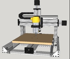
  1. Metalguru

    Metalguru Veteran
    Builder

    Joined:
    Dec 29, 2015
    Messages:
    752
    Likes Received:
    545
    Metalguru published a new build:

    Read more about this build...
     
  2. Mark Carew

    Mark Carew OpenBuilds Team
    Staff Member Moderator Builder Resident Builder

    Joined:
    Jun 28, 2013
    Messages:
    2,741
    Likes Received:
    2,407
    Great job on these mods and upgrades @Metalguru I see a lot of helpful ideas here to make the C-Beam machine a much more robust system. Having a community working together like this really helps to build these machines into the best they can be and we all learn from it along the way. These community driven ideas are what will inspire a V2 ;) Thank you for taking the time to share.
    Mark
     
    MaryD likes this.
  3. Metalguru

    Metalguru Veteran
    Builder

    Joined:
    Dec 29, 2015
    Messages:
    752
    Likes Received:
    545
    Thanks, Mark. I was hoping you could incorporate some of these ideas into a V2 kit. Contact me if you want to collablrate further on this.

    MG
     
    Mark Carew likes this.
  4. Kevin Kuehn

    Builder

    Joined:
    Apr 2, 2016
    Messages:
    5
    Likes Received:
    6
    Do you have a parts list for this build? I'm interested in doing these mods, but I have no experience building machines.
     
  5. Metalguru

    Metalguru Veteran
    Builder

    Joined:
    Dec 29, 2015
    Messages:
    752
    Likes Received:
    545
    You should be able to generate a parts list from the Sketchup model just by making a manual list. Just go through the model and write down all the parts used. I don't use BOM's because I am a custom builder and have an extensive stock of parts, so I just go get what I need off the shelf.

    I did notice that someone revamped the model to include names for all the parts. I have not looked at this SKP file to see what is different. Also, I have made some changes to the SKP design since doing this build, as a result of the build. I have not included these changes in the SKP file yet.

    Edited Model: CNC design (parts named)

    MG
     
    pedrofernandez likes this.
  6. pedrofernandez

    pedrofernandez Journeyman
    Builder Resident Builder

    Joined:
    May 14, 2017
    Messages:
    148
    Likes Received:
    218
    Hey Dude, love your idea and did it, used the leftovers to mount my surface tablet thanks ill post a photo soon...
     

    Attached Files:

    MaryD, Metalguru and Scotty Orr like this.
  7. Metalguru

    Metalguru Veteran
    Builder

    Joined:
    Dec 29, 2015
    Messages:
    752
    Likes Received:
    545
    Nice job! Although you could have made your table a lot bigger to take advantage of the extra travel. You can always do that later. Or, go with the v-slot table.

    Also, you can put your wheels closer together to make the rails stick out a bit less front and rear. Shouldn't affect the stability much.

    Now, get a dial gauage and dial in the table for flatness.

    MG
     
  8. pedrofernandez

    pedrofernandez Journeyman
    Builder Resident Builder

    Joined:
    May 14, 2017
    Messages:
    148
    Likes Received:
    218
    i used some leftovers to make the build, ill post an update as soon i go to the hardware store, but talking about the v-slot table what clearance you have between the table and the Z axis actuator?
     
  9. Metalguru

    Metalguru Veteran
    Builder

    Joined:
    Dec 29, 2015
    Messages:
    752
    Likes Received:
    545
    As much as you want. Just move the Z axisup for more clearance. You can adjust it right up to the bottom of the gantry plate. I also used the CBXL gantry plate on the X axis as well as the Y, and the Z axis just bolts on with 4 screws.

    I may have forgot to mention that I made the C-beam side supports 50mm taller than the original so I could have extra clearance.

    MG
     
  10. pedrofernandez

    pedrofernandez Journeyman
    Builder Resident Builder

    Joined:
    May 14, 2017
    Messages:
    148
    Likes Received:
    218
    dam i didn't pay attention to the 300mm c-beams thought was 250 argg
     
  11. Kevin Kuehn

    Builder

    Joined:
    Apr 2, 2016
    Messages:
    5
    Likes Received:
    6
    That's why a parts list would be helpful, I probably would have made the same mistake
     
  12. pedrofernandez

    pedrofernandez Journeyman
    Builder Resident Builder

    Joined:
    May 14, 2017
    Messages:
    148
    Likes Received:
    218
    But 100 sq inches more is good anyways!!!
     

    Attached Files:

  13. Metalguru

    Metalguru Veteran
    Builder

    Joined:
    Dec 29, 2015
    Messages:
    752
    Likes Received:
    545
    You could raise your X axis beam up another 20mm by putting cast corner brackets on top of the C-beams at each end instead of the flat 5 hole corner plates. That way you are still supporting the X axis c-beam but it will be 20mm above the top of the vertical c-beams.

    Also, with the aluminum table, you could also probably get away with 1/2" MDF spoil board as well, giving another 6.35mm of clearance. That's over an inch of extra Z axis travel total...

    And Kevin Kuehn, you have the Sketchup model, and Sketchup has a tape measure... We don' need no steenkin' parts list :) Or, you could volunteer to do up a BOM, I think there is a way to do it in Sketchup, but I've never tried it.

    MG
     
    Giarc likes this.
  14. pedrofernandez

    pedrofernandez Journeyman
    Builder Resident Builder

    Joined:
    May 14, 2017
    Messages:
    148
    Likes Received:
    218
    make sence, i end up with 45mm clearance on the Z, can be 65mm, my final cutting area is (340mm "Y" axis) by (405mm "X" axis)
     
  15. pedrofernandez

    pedrofernandez Journeyman
    Builder Resident Builder

    Joined:
    May 14, 2017
    Messages:
    148
    Likes Received:
    218
    hello metalguru, i have cut all the plates to transform the machine into a sphinx type but no way ill keep this one as is is working super and thank you, but for the next build i was looking into this drivers on ebay (
    TB6560 3A Driver Board
    for bigger steppers that you recommend in other post and i have a couple arduino unos that i can flash with grbl, are the setup is to complicated with those? im planning to use the 425oz motors
     
    #15 pedrofernandez, Dec 17, 2017
    Last edited: Dec 17, 2017
  16. Metalguru

    Metalguru Veteran
    Builder

    Joined:
    Dec 29, 2015
    Messages:
    752
    Likes Received:
    545
    Hey Pedro:

    Your link above did not work so I am not sure which ones you are referring to. The ones I use are from SainSmart, and are pretty reliable:

    Single-Axis CNC Stepper Motor Driver Controller, TB6560.

    They have a stocking warehouse in the US.

    Note that the switch settings are shown by the silkscreen on the board, and NOT the indication printed on the switch itself. Set the Decay mode for the quietest operation of the motor, you will find that the motors can be set to be extremely quiet running using the decay mode switches.

    Also, these can be set upt to 3A, so if your motors are 3A or 2.8A max current you are set.

    There are lots of similar ones on eBay like this:
    upload_2017-12-17_16-32-4.jpeg
    I would NOT recommend the ones that look like this:

    upload_2017-12-17_16-33-10.jpeg

    As they are cheaply made, have a small heatsink, and are difficult to mount. Also, in some cases, the heatsink and mounting holes are not isolated from the electrical circuit of the board, so if you use metal hardware to mount them onto a metal plate they go up in smoke.

    Hope this helps.

    MG
     
    GrayUK likes this.
  17. cmwwebfx

    cmwwebfx New
    Builder

    Joined:
    Dec 2, 2017
    Messages:
    62
    Likes Received:
    5
    I there any reason Linear rails could not have been used on the outer sides of the spoil board rather than wheels?
     
  18. Metalguru

    Metalguru Veteran
    Builder

    Joined:
    Dec 29, 2015
    Messages:
    752
    Likes Received:
    545
    Just cost. I was trying to keep the costs in line with the original machine. My own personal machine has linear rails on it.
    Also, it's a lot easier to get the table level with the X axis, with the linear rails you have to use shims, with the wheels it's a simple adjustment.


    20160714_164538.jpg


    This photo was taken before I upgraded to C-Beam verticals for X axis support. I lost about 40mm of X travel, but the machine is a lot stiffer. This machine now also has a double wide Z axis gantry plate with a double router mount, and CBXL gantry plates on X and Y, instead of the universal build plates.

    Below is a photo of the last machine I built using the wheels, c-beam uprights, and a v-slot table.

    20171026_165234.jpg

    MG
     
    cmwwebfx likes this.
  19. GrayUK

    GrayUK Openbuilds Team Elder
    Staff Member Moderator Builder

    Joined:
    May 5, 2014
    Messages:
    1,668
    Likes Received:
    627
    Hi MG.
    Any chance of seeing a few more photos, or a video, of the machine above, from different angles please?
    Gray
     
    cmwwebfx likes this.
  20. Metalguru

    Metalguru Veteran
    Builder

    Joined:
    Dec 29, 2015
    Messages:
    752
    Likes Received:
    545
    Sure, Gray, here you are:

    C-Beam Machine 3 Magrum 1.jpg

    20171026_165018.jpg

    20171026_164953.jpg


    20171026_165106.jpg


    20171026_165050.jpg


    C-Beam Machine 3 Magrum 3.jpg

    These are all the photos I have, so I stuck in a couple of renderings from the Sketchup model. The model is available in the build:

    Improved CBM

    I have to do a couple of updates on the model, I will try to put it up a bit later.

    MG
     
  21. GrayUK

    GrayUK Openbuilds Team Elder
    Staff Member Moderator Builder

    Joined:
    May 5, 2014
    Messages:
    1,668
    Likes Received:
    627
    MANY THANKS MG
     
  22. Petr86

    Petr86 New
    Builder

    Joined:
    Dec 17, 2020
    Messages:
    1
    Likes Received:
    0
    Great construction! Will updated SketchUp model be available?
     
  23. Metalguru

    Metalguru Veteran
    Builder

    Joined:
    Dec 29, 2015
    Messages:
    752
    Likes Received:
    545
    This post is 3 years old. There will be no more updates. See CNC design (parts named).

    My latest Sketchup file is included.
     

    Attached Files:

    Nirkki likes this.
  24. Ronald4418

    Ronald4418 Well-Known
    Builder

    Joined:
    Nov 4, 2015
    Messages:
    218
    Likes Received:
    33
    What size is the Aluminum Angle you used to make the outriggers from? I have 2 Y-Axis on my C-Beam Xl and for the life of me can't get them to run in sync.
     
  25. Ronald4418

    Ronald4418 Well-Known
    Builder

    Joined:
    Nov 4, 2015
    Messages:
    218
    Likes Received:
    33
    I purchased some 2" Angle to make the outriggers but can't find any relevant information as to the Drilled Height for the wheels for the outrigger. Is this 10mm or more?
    I plan on using eccentrics instead of Spacers so the I can adjust everything.
     

Share This Page

  1. This site uses cookies to help personalise content, tailor your experience and to keep you logged in if you register.
    By continuing to use this site, you are consenting to our use of cookies.
    Dismiss Notice