
This is my second attempt at improving the C-Beam Machine. The first was documented elsewhere on this list. (C-Beam Machine Too) It involved the addition of some Chinese linear rails and a lot of changes based on reusing most of the original components of the CBM kit. That build evolved over time as I was building my own machine to mill aluminum.
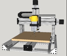
I have now built one of these, after I put some thought into how to improve the original design without going overboard. I shamelessly stole some of the concepts from the C-Beam XL design, as well as another author who had the idea for the wheel supported table, unfortunately I can't remember who first came up with this to give him the credit. The redesign has several advantages over the original:
1. It uses low cost stock components, and the cost to build should be not too much higher than the original. There are some added components which will increase the cost, but shouldn't be more than 10% or so. I have not costed out this model yet so I am not sure on this.
2. The machineable area is almost doubled over the original design, almost 380x380mm, where the original was 300x280mm.
3. I used C-Beam for the support uprights, which is more compact and stronger than the original
4. I also used C-Beam XL plates for the X and Y axes, which are inherently stronger and use 50% more wheels
5. I added additional support for the table by putting 4 more wheels on the outboard edges of the table. This increases stability and support immensely over the original which was a bit wobbly on the table, especially when cutting near the extremes of X axis travel.
6. I used the double wide C-Beam gantry plate for the Z axis, which is much stronger, doubles the number of wheels, and allows for a double router mount. (see Extra Strong Double Router Mount)
Let's go through the list above in some greater detail.
Going with the C-Beam XL plates gives us 6 wheels instead of 4 on the X and Y axes. These plates are thicker and much stronger than the small Universal Build Plates on the original. It also simplifies mounting of the Z axis, and in the case of the Y axis is stronger than the Universal Build Plate used in the original design. Using the smaller CBXL plate also gives us a large increase in Y axis travel. The CBXL plates also allow the use of dual nut blocks, which gives much better support and strength to the leadscrew.
The spoil board is elevated a bit over the original design so it can fit over top of the Y axis motor, further increasing Y axis travel. Overall, Y axis travel is increased by almost 100mm.
Using C-beams for the uprights has several advantages over the original design:
- They are stronger and more compact
- each upright is a single piece
- They can be joined together top and bottom by 20x40 braces, which increases the overall rigidity
- The X axis beam can be better supported top and bottom
- Since the C-beams are thinner than the original 20x60's, coupled with the different placement of the top corner brackets, the X axis travel is increased by almost 80mm from stock without changing the length of the X axis C-Beam.
The spoil board on the original design had a lot of flex vertically on the extremes of travel. It was essentially just supported in the center by the thin Universal Build Plate, and nothing held it from flexing up and down when the X axis moved across it. I addressed this problem by adding a couple of pieces of 1.5x1.5x1/8" aluminum angle under the spoil board on each side. (this angle is available from Home Depot) Drilling these angles for offset spacers allowed adding a couple of wheels to support the edges of the table. This almost completely eliminates up and down movement of the table edges under load, and allows for adjustment to level the table WRT the X axis.
The wheels run in a couple of 20x20 v-slot tracks fastened to the cross pieces of the base. In the drawing shown, the wheels are about 200mm apart. This keeps the length of the tracks to just a bit longer than the base assembly. If one were to increase the spacing on the wheels, the table would have more stability front to back as well as side to side, but it would necessitate increasing the length of the v-slot tracks so they stick out more past the ends of the base. If you have the room, this is a good option.
The table also benefits from the 1.5"" angle making it much stiffer front to back. It is well supported in the center by the gantry plate, making the whole assembly stiff and strong. The MDF spoil board could be easily replaced with a 1/4" aluminum table, which would allow the machine to use mist cooling for cutting aluminum. You could also easily convert this to a v-slot table and have lots of t-slots to put hold downs. The aluminum table could also have tapped holes added for hold downs, a vice, or t-slots for work holding.
Finally, the Z axis is beefed up by adding a double wide C-Beam gantry plate for extra strength. This limits the travel somewhat, but this machine has limited space between the X axis and bed anyway. Spacing is still more than sufficient to get more than 3" of Z travel. The double gantry plate also allows the use of 2 standard OB router mounts one above the other, and with the Dewalt or similar routers with the long barrel, adds a lot of strength to the Z axis.
The liberal sprinkling of 5 hole corner brackets to support the base, uprights, and X axis beam also add a lot of strength ot the design. 6 hole corner brackets and cast corner brackets are also used throughout to tie various elements together.
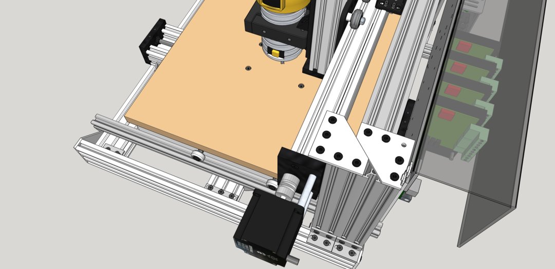
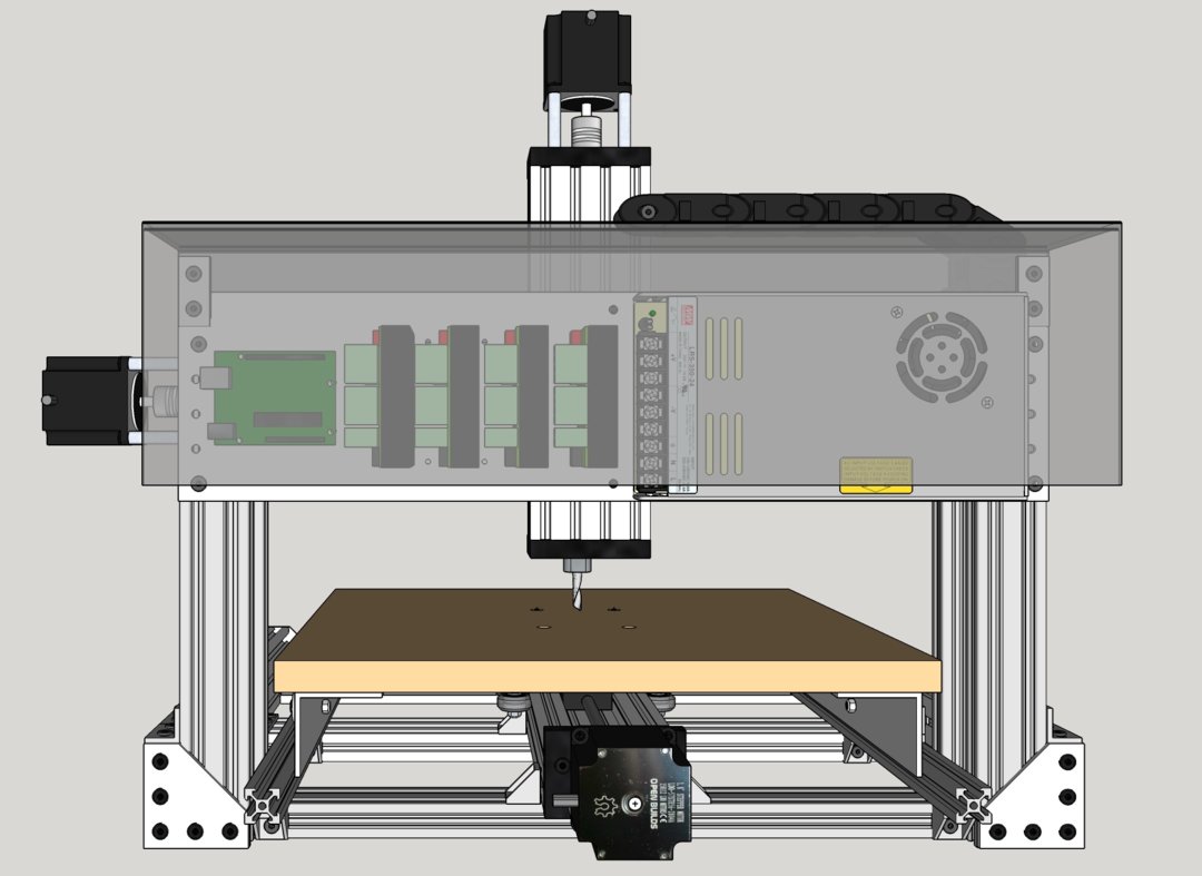
The rear view shows my signature Electronics Panel with Dust Cover that I use to build all my machines. I have these panels punched by a local panel shop, they are 500mm x 120mm, have hole patterns that fit the power supply, an Arduino Nano screw terminal board (they are not drilled for the Arduino Uno as shown), along with 4 sets of holes for various stepper drivers including the DQ542's. I can sell them for $30 each, and the dust covers are also $30 each.
UPDATE:
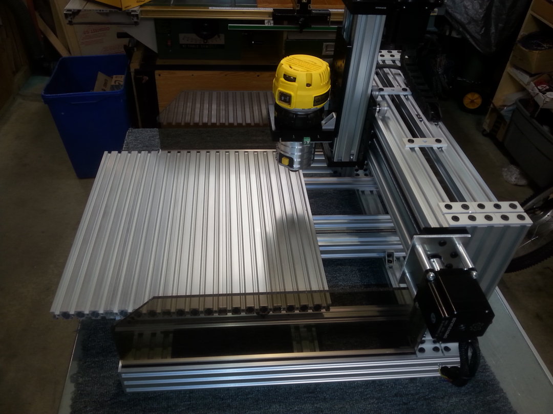
So, I actually built this recently. Worked out pretty well. An order of magnitude stronger that the original at roughly the same price. It's got a couple of minor changes from the model above, but essentially the same. Here are some photos:
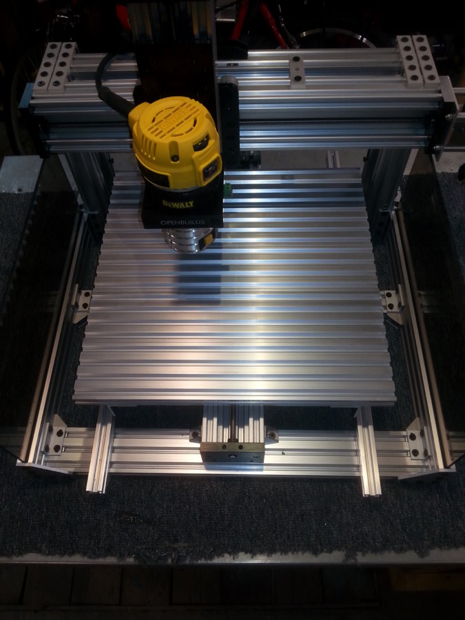
As you can see, I made an aluminum table for it. Turned out to be really simple to make and only cost a few dollars extra. I used 5 pieces of 20x80 cut to 400mm long, tied together underneath by 2 1.5"x1.5"x1/8" aluminum angles. I drilled 10 holes in the angles so I could put a screw in on each side of the joints plus one at each end. Very strong. The screws on each side of the joint hold the table very flat, and the angle adds a lot of stiffness to the table.
The CBXL plate on the Y axis is installed with 6 wheels, and the bed is screwed onto it with 4 screws into t-nuts on the center 20x80. There is 12mm of spacer and a slot washer on each screw. This raises the table up enough so it clears the Y axis motor in the back, allowing it to have the full 375mm of travel.
You may also notice that the 5 hole corner brackets on top of the side C-Beam supports were replaced with 2 and 3 hole joiner plates. You can also see I put a couple of 3 hole joiner plates across between the top 20x40 and the c-beam X axis to add a bit of stiffness.
Also, you can see in this photo I put in the motor mount plates I had made which support the motor much better using 4 35mm standoffs. The 1/8" aluminum plate just bolts on right over the c-beam end plate. I now use these for all motor mounts on lead screw axes.
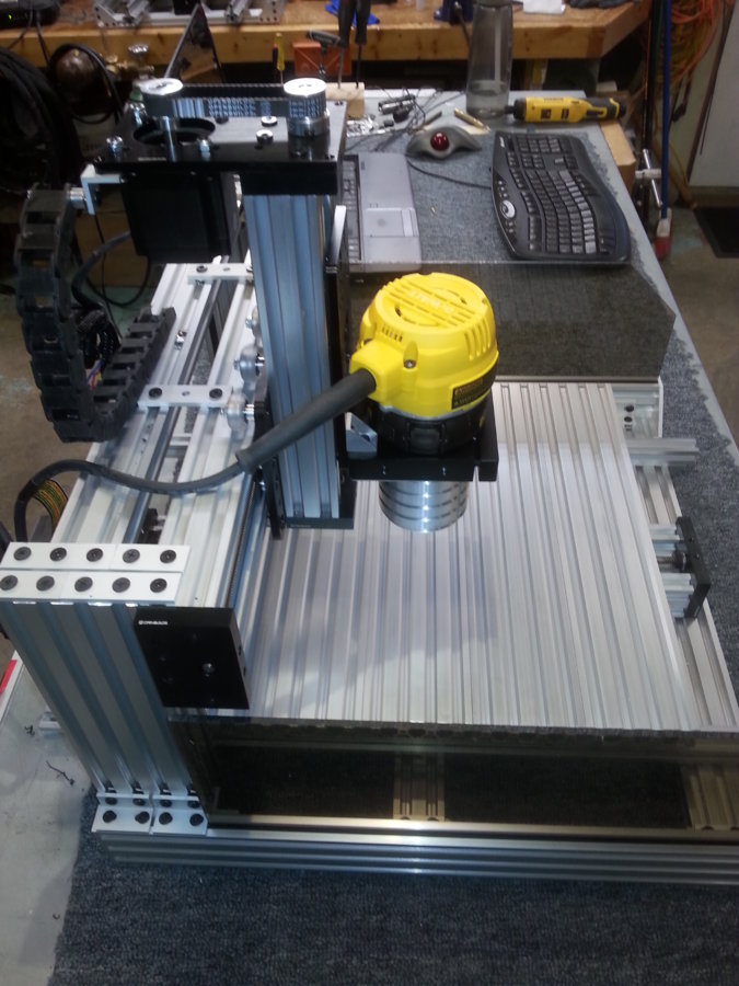
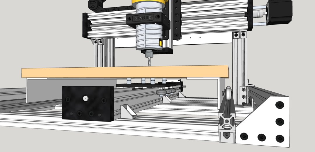
Another side view showing the belt drive Z axis. It uses the double wide C-beam gantry plate with the router mount right at the bottom. It would be very simple to double up on the router mounts to make the assembly stronger. The router mount is screwed through from the back on the bottom set of holes on the CB plate, as well as having the two cast corner brackets.
The Z axis mounts to the X axis CBXL plate with 4 screws (between the wheels) into tee nuts in the outer slots on the back of the C-Beam. This allows the whole Z axis to be adjusted up and down to vary the machining height, as well as easily removed if needed.
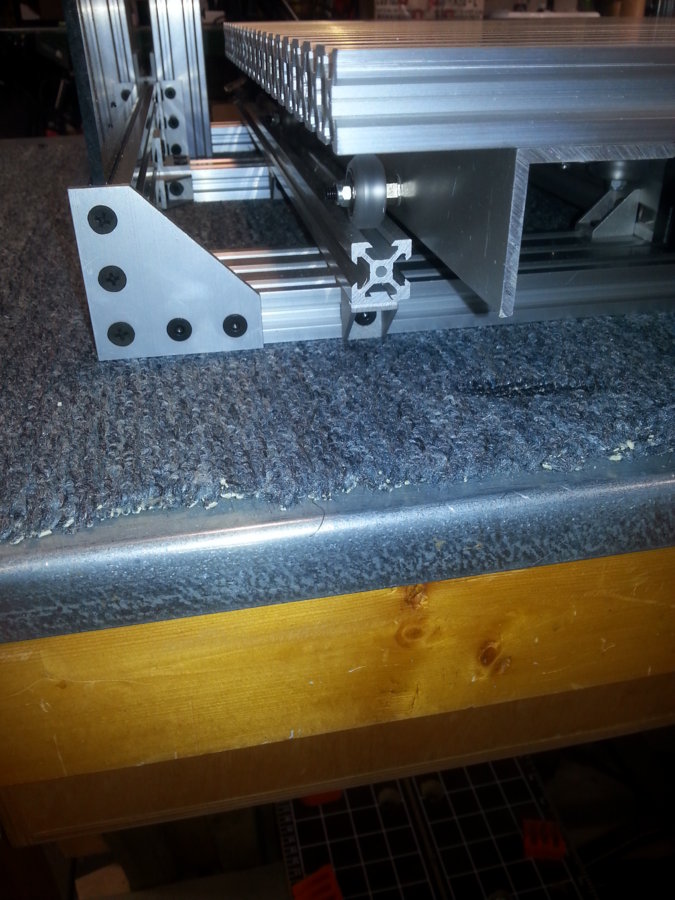
Here's a closeup showing the wheels supporting the table on each side, running in a 20x20 v-slot mounted on the bottom cross rails. (I added a second cross rail in the middle of the base for added strength over the original CBM design) The wheel holes ended up a bit close to the edge of the angle, so I inserted 3 hole joiner plates between the 20x20 and the cross rail to lift up the 20x20 by 4mm. This put the wheel hole a bit farther from the edge. All 4 wheels have offset bushings so they can be adjusted individually. The 20x20 is held on to the cross braces by a cast corner bracket underneath. The bracket is screwed through the 3 hole joiner plate to hold it in place. There are 3 cast brackets, and 3 joiner plates, one for each crossmember in the base, on each rail.
Note: It would have been better in hindsight to use 2x2" angle instead of 1.5x1.5". This would have made the base easier to assemble and not require the extra spacers under the 20x20 rails. I also moved the offset spacers from the inside of the angle where they are almost impossible to adjust to the outside. Now they can be easily reached with a wrench. I was able to level the bed on this machine to within +/- 0.2 mm with no problems, both front to back and side to side.
That's it for now. I'll add one more photo when the electronics are added. This was a pretty straight forward build, and ended up to be a very nice medium sized machine, with a machining area of about 375x375mm. Quite the improvement over the original CBM.
I'll also update the Sketchup model to show all the changes mentioned one of these days.
Start a conversation if you need more info.
Improved CBM
Build in 'X/Y Table Style CNC Mill' published by Metalguru, Dec 9, 2020.
Yet another build of an improved C-Beam Machine, improving stiffness, size, versatility, and strength without increasing costs much.
-
-
Build Author Metalguru, Find all builds by Metalguru
-
- Loading...
-
Build Details
- Build License:
-
- CC - Attribution NonCommercial - CC BY NC
Reason for this Build
To improve the original designInspired by
Mark Carew and Moag, co authors of the C-Beam XL build, and Unknown author who first suggested the wheeled support for the table