Welcome to Our Community

Some features disabled for guests. Register Today.

GTC2020

Discussion in 'CNC Mills/Routers' started by GinoTheCop, Jan 5, 2020.
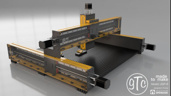
  1. GinoTheCop

    GinoTheCop Journeyman
    Builder

    Joined:
    Jan 28, 2016
    Messages:
    150
    Likes Received:
    196
    GinoTheCop published a new build:

    Read more about this build...
     
  2. GinoTheCop

    GinoTheCop Journeyman
    Builder

    Joined:
    Jan 28, 2016
    Messages:
    150
    Likes Received:
    196
    OK here we go..! Wish me luck but I must warn you this will be a slow build...

    An eye candy from the latest stage of the design:

    [​IMG]
     
    MaryD and Giarc like this.
  3. GinoTheCop

    GinoTheCop Journeyman
    Builder

    Joined:
    Jan 28, 2016
    Messages:
    150
    Likes Received:
    196
    OK the design is almost finished.. It seems it will be;

    Y(travel) = 815mm
    Y(cut) = 800 mm
    X(travel)= 720mm
    X(cut)=720 mm
    Z(travel)= 160 mm

    Those numbers might change slightly but looks like this is what it's going to be.

    And another render from where the current design is:

    [​IMG]
     
  4. GinoTheCop

    GinoTheCop Journeyman
    Builder

    Joined:
    Jan 28, 2016
    Messages:
    150
    Likes Received:
    196
    Design almost finished.. Added some coated colors for eye-candy..

    [​IMG]
     
    William Schmiedlin likes this.
  5. GinoTheCop

    GinoTheCop Journeyman
    Builder

    Joined:
    Jan 28, 2016
    Messages:
    150
    Likes Received:
    196
    And the bones .. :)

    [​IMG]
     
  6. GinoTheCop

    GinoTheCop Journeyman
    Builder

    Joined:
    Jan 28, 2016
    Messages:
    150
    Likes Received:
    196
    489 screws :jawdrop:

    [​IMG]
     
    Rachel Holley likes this.
  7. GinoTheCop

    GinoTheCop Journeyman
    Builder

    Joined:
    Jan 28, 2016
    Messages:
    150
    Likes Received:
    196
    #7 GinoTheCop, Feb 1, 2020
    Last edited: Feb 2, 2020
    Rob Taylor and Alex Chambers like this.
  8. Rob Taylor

    Rob Taylor Master
    Builder

    Joined:
    Dec 15, 2013
    Messages:
    1,470
    Likes Received:
    746
    I have a very similar machine idea floating around in my head. A little larger X/Z travels, but same setup and modularity/upgradability. The great thing is, something as beefy as this can be built for around the same price as a pre-configured kit, just takes a little more work.

    A view with just the extrusion beams with no covers would be cool as well.
     
  9. phil from seattle

    phil from seattle Journeyman
    Builder

    Joined:
    Mar 17, 2017
    Messages:
    312
    Likes Received:
    137
    I don't understand how the X and Y rails are constructed. It looks like they are boxes made of sheet material. I must be missing something as that won't be very strong/rigid.
     
  10. Rob Taylor

    Rob Taylor Master
    Builder

    Joined:
    Dec 15, 2013
    Messages:
    1,470
    Likes Received:
    746
    Good call. I thought there was extrusion hidden inside the sheet metal. Kinda confused now. Those gantry plates are also looking about a third to a quarter of the thickness they likely need to be, sans any other reinforcement.
     
  11. phil from seattle

    phil from seattle Journeyman
    Builder

    Joined:
    Mar 17, 2017
    Messages:
    312
    Likes Received:
    137
    If the gantry plates are steel they might be ok. AL - would need to be 10-12mm thick at least.
     
  12. GinoTheCop

    GinoTheCop Journeyman
    Builder

    Joined:
    Jan 28, 2016
    Messages:
    150
    Likes Received:
    196
    Hi, thank you for your comments.. They are very valuable for me..

    I was thinking most of the load/strength will be needed on two part types..

    One is the back plates (the red parts on this draft) and gantries. I might go for steel for those two and add 90 degree extrusion to connect back plates to v-slots (machine bed)

    6 mm alu gantries do a good job with C-Beams.. But then again ofc steel would be much more sturdy and if gantries are seteel back plates will have to be steel too..

    The yellow parts are just alu sheets to make the box and they connect to back plates and everything else with corner connectors. They do not receive weight or pressure on them at all. I am more worried about the feet to be honest as I have a Y connector down below and I can only use feets on the outer edges of the bottom plates.

    model-draft.jpg
     
    Aleks13 likes this.
  13. phil from seattle

    phil from seattle Journeyman
    Builder

    Joined:
    Mar 17, 2017
    Messages:
    312
    Likes Received:
    137
    What thickness are you thinking for the back plates? If I were you, I'd build up a test beam, attach a lever (proxy for the Z beam) at the center and see how easy it is to deflect the lever. I'd be very concerned that it will flex too much.
     
  14. GinoTheCop

    GinoTheCop Journeyman
    Builder

    Joined:
    Jan 28, 2016
    Messages:
    150
    Likes Received:
    196
    Was thinking 6 mms for backplates
     
  15. GinoTheCop

    GinoTheCop Journeyman
    Builder

    Joined:
    Jan 28, 2016
    Messages:
    150
    Likes Received:
    196
    What about 10mm 7075 Aluminum? Do you think that will do it?
     
  16. phil from seattle

    phil from seattle Journeyman
    Builder

    Joined:
    Mar 17, 2017
    Messages:
    312
    Likes Received:
    137
    I honestly don't know, that engineering is beyond me. If I were doing it, I'd find some one who can do that kind of analysis.
     
  17. Rob Taylor

    Rob Taylor Master
    Builder

    Joined:
    Dec 15, 2013
    Messages:
    1,470
    Likes Received:
    746
    Not sure I'd be slapping "Machine Design" with my logo all over a bunch of pretty renders if I hadn't done some basic mechanical testing and analyses, though. ;)

    Sure does look pretty, but it's gonna be making oval holes and snapping tooling all over the place.
     
  18. GinoTheCop

    GinoTheCop Journeyman
    Builder

    Joined:
    Jan 28, 2016
    Messages:
    150
    Likes Received:
    196
    Well, true I like designing and making them look pretty. But not going to start building once I am 100% sure it is not going to make oval holes and tool snapping all over the place.

    Please note that this is not a commercial product or what so ever. This is me playing around only as a hobby.

    Would appreciate some productive input as I believe thats one of the philosophy of "open" building.

    Sure I could easily take this to bunch of friends in the University but then it wouldn't be so much fun (at least not for me)..

    Thank you for your "input" anyways as now I realize you are right.. This could be misleading.. Will change the pictures when I have time..

    "EDIT: Deleted the medium with "machinery design"
     
    #18 GinoTheCop, Feb 2, 2020
    Last edited: Feb 2, 2020
  19. Rob Taylor

    Rob Taylor Master
    Builder

    Joined:
    Dec 15, 2013
    Messages:
    1,470
    Likes Received:
    746
    Good answer. :)

    The fix is relatively simple: stop assuming your linear rail has any structural integrity whatsoever. Now design a machine frame that's going to hold it solidly in place. It can't flex in any direction or on any axis, for which plain sheet metal is the worst possible performer for all of these tasks. Now if your "sheet metal" was actually 3/4" aluminum bar stock, machined flat on both sides, maybe that would work. Unnecessarily expensive, though!
     
  20. GinoTheCop

    GinoTheCop Journeyman
    Builder

    Joined:
    Jan 28, 2016
    Messages:
    150
    Likes Received:
    196
    Thank you. In my mind I was not relying the integrity of my linear rails.. I was more relying on "back plates" as those are the ones that holds everything together. However your comment makes it obvious that sheets are not going to do it.

    In this case I am going to use c-beams again and come up with a design that keeps everything in a box for clean operating. (I also like the idea of having a polycarbonate "window" to see the goodies move while operating. :):thumbsup:
     
  21. Rob Taylor

    Rob Taylor Master
    Builder

    Joined:
    Dec 15, 2013
    Messages:
    1,470
    Likes Received:
    746
    Fwiw, my design in my head is C-Beam based. It's the best bang-for-buck I've seen out there, and if it's rigidly held down to a work surface, the weak point is likely the lips holding the M5 tee-nuts in, not anything else.

    It doesn't look as cool as a truly custom design, I know, but without access to a medium/large VMC- VF2 or larger- it's difficult to create a long, strong, reasonably flat (+/- 0.001"/0.025mm or less) surface. Welded rib/spar construction would work well and provide mounting flanges, but again it would need machining flat at the end.
     
  22. GinoTheCop

    GinoTheCop Journeyman
    Builder

    Joined:
    Jan 28, 2016
    Messages:
    150
    Likes Received:
    196
    True.. Maybe its better to go for a smaller machine.. As you probably know I design, build and donate the machines to tech high schools so that they can use them for learning (like i do) and using for their projects. :)
     
    Rob Taylor likes this.
  23. GinoTheCop

    GinoTheCop Journeyman
    Builder

    Joined:
    Jan 28, 2016
    Messages:
    150
    Likes Received:
    196
    Mark Carew likes this.
  24. GinoTheCop

    GinoTheCop Journeyman
    Builder

    Joined:
    Jan 28, 2016
    Messages:
    150
    Likes Received:
    196
    I've used C-Beam before and it works great. The machine was a success.. C-BEAM-GTC

    I would like to go for something else this time.. Maybe something like this? 2 20x60 v-slots between 2 10mm 7075 plates. 1 has a recess for housing the linear rail as it is critical for 2 reasons 1 to have them lay in parallel, two help the machine to absorb the vertical or horizontal force.

    Mod4-XY-Extrusion-v9.png
     
  25. Rob Taylor

    Rob Taylor Master
    Builder

    Joined:
    Dec 15, 2013
    Messages:
    1,470
    Likes Received:
    746
    Those are quite complex plates. Recess grooves on one side and undercut T-slots on the other. Do you have the capacity to manufacture those +/-0.005mm? If you can't manufacture precision, you have to manufacture adjustability. The linear rails will need sweeping in with a test indicator; best practice is probably to assume they're going to come wiggly and figure out how to make them accurate.

    So, it looks cool, and I like the overall strength, I just don't know if it's manufacturable.
     
  26. GinoTheCop

    GinoTheCop Journeyman
    Builder

    Joined:
    Jan 28, 2016
    Messages:
    150
    Likes Received:
    196
    Yes of course manufacturing is not a problem. Would you think t-nuts is a better solution?
     
  27. phil from seattle

    phil from seattle Journeyman
    Builder

    Joined:
    Mar 17, 2017
    Messages:
    312
    Likes Received:
    137
    I think simple grooves are enough with tnuts. It would be interesting to see an FEA of the assembly to see how it handles torsion.
     
  28. GinoTheCop

    GinoTheCop Journeyman
    Builder

    Joined:
    Jan 28, 2016
    Messages:
    150
    Likes Received:
    196
    Easier too yeah.. I am investigating fusion360' s analysis capabilities. As you can define the type of the material and surfaces, moving parts, etc it comes up with results showing the weak spots. Not sure if it will help but worths a try.
     
  29. Mark Carew

    Mark Carew OpenBuilds Team
    Staff Member Moderator Builder Resident Builder

    Joined:
    Jun 28, 2013
    Messages:
    2,741
    Likes Received:
    2,407
    This is a great discussion with a lot of ideas and this great looking machine @GinoTheCop :thumbsup:
     
  30. GinoTheCop

    GinoTheCop Journeyman
    Builder

    Joined:
    Jan 28, 2016
    Messages:
    150
    Likes Received:
    196
    Thank you Mark.. There still much to do.. I am working on ver. 4 of this build now :)
     

Share This Page

  1. This site uses cookies to help personalise content, tailor your experience and to keep you logged in if you register.
    By continuing to use this site, you are consenting to our use of cookies.
    Dismiss Notice