Welcome to Our Community

Some features disabled for guests. Register Today.

Gigantesque CNC

Discussion in 'CNC Mills/Routers' started by Corey Corbin, Feb 22, 2021.

  1. Corey Corbin

    Corey Corbin Well-Known
    Builder

    Joined:
    Feb 27, 2016
    Messages:
    135
    Likes Received:
    62
    Corey Corbin published a new build:

    Read more about this build...
     
  2. Rob Taylor

    Rob Taylor Master
    Builder

    Joined:
    Dec 15, 2013
    Messages:
    1,470
    Likes Received:
    746
    Looks promising. Heavier plates are definitely a must, I have 3/4" and 1/2" on mine due to the sheer length of them, but these 3/8" look proportional to the smaller overall build.

    @Kevon Ritter also did a opposing-U C-Beam build, a year before I even started designing mine. I don't think I copied it because I didn't actually realize that was his setup until recently, but at the very least additional credit where due.

    I like the embracing of limitations, though. I didn't even try to start building CNC machines until I had a mill, lathe and oscilloscope!:ROFL:
     
    Mark Carew likes this.
  3. JustinTime

    JustinTime Veteran
    Builder

    Joined:
    Dec 18, 2013
    Messages:
    775
    Likes Received:
    256
    A Sillyscope? How does a Sillyscope comes to play with building a CNC machine?
     
  4. ljvb

    ljvb Well-Known
    Builder

    Joined:
    Feb 14, 2019
    Messages:
    276
    Likes Received:
    87
    Just like everything else.. a reason to buy a new tool... :) They need a support group for people like me (... us??).. I find myself collecting tools more than using those tools to build anything.... :)
     
  5. Corey Corbin

    Corey Corbin Well-Known
    Builder

    Joined:
    Feb 27, 2016
    Messages:
    135
    Likes Received:
    62
    I liked your idea of the dbl c beam setup. your project spurred the creative juices to start one like yours. But I didn't want to build something fancy with nice beautiful curves and pockets for the nuts and bolts and needed a another machine to build. Something that can be built with common hand and power tools. I also needed a little bigger machine then the current one. I wanted to place a vise in the belly of the machine if needed. I wanted to use 2.2kw spindle for the ER20 collet. Following your M4: 1510SS project with all the simulations of how aluminum flex. How too sturdy the alum ext was the question? There's various threads on filling the c beam with different materials.Sounds messy. But I was planing to try running a common steel rod that could be bought from hardware store. With the HGR20 rail on the front and a rod thru the extrusion. Threaded on both ends thru hole to the upright plate and use a nut or bolt to place a certain amount of torque running thru the c beam. Might have to file or grind a flat spot the length of the rod a bit. This idea plays off the tingle system for lead screws. Here's a crude drawing. But maybe a couple of rods thru the extrusion might rigid it up some. I am favoring the thicker rod with a internal thread and a bolt more then the all thread style.

    [​IMG]
     
  6. Rob Taylor

    Rob Taylor Master
    Builder

    Joined:
    Dec 15, 2013
    Messages:
    1,470
    Likes Received:
    746
    CNC is just a whole bunch of high speed pulse trains, varying analog signals, and synchronized signals. The only way to have any clue what's going on in there over the course of the couple microseconds in which it happens is with an oscilloscope. A multimeter can help with "is this switch actually working?" and "is this getting power?" but that's about the extent of it.

    Should be interesting to see, I like it. I thought about reinforcing my gantry even more, but I think I'm gonna leave it for now and see how much it moves first. If it does move, I think I may try the rebar and epoxy method, but I'd look into seeing whether tension really helps a lot or not as well, just in case. My gut feeling is that it probably doesn't, because it's not like a pre-stressed concrete structure where you need the tensile force in place ahead of time to take up additional forces later in a weak material. Using epoxy or an epoxy granite type mix to fill the gap like Loctite (which doesn't stick fasteners together, it fills the threads to prevent the clearance required to move) should do the job, but I haven't looked into it much, so I'm not really sure.
     
  7. Corey Corbin

    Corey Corbin Well-Known
    Builder

    Joined:
    Feb 27, 2016
    Messages:
    135
    Likes Received:
    62
    You might be right all the extra work and steel rod not going help a whole lot. So next thought is I left on back side of the c beam I left a 1/8 lip be able to place a 1/8th thick piece of sheet metal to act as binder for the 2 pieces. This is on my current machine. I had made the X axis plate a little taller so I added a 20x40 ext on top to make up the height. But I wanted to place 1/8in sheet metal just to give it stability between the 2 pieces. I thinking same thing for new machine. This was my initial idea. SO i think I am gonna subscribe to Fusion 360 for a month I would like to see if I can learn and run the simulatons and see how steel and aluminum perform.
    [​IMG]
     
  8. Corey Corbin

    Corey Corbin Well-Known
    Builder

    Joined:
    Feb 27, 2016
    Messages:
    135
    Likes Received:
    62
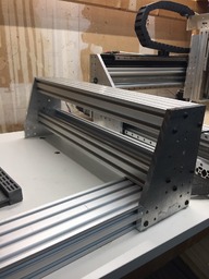
    Some of my parts arrived, I finished some end plates and kind of mocked build my x axis. Just to see if my layout lined up. Went together pretty easy. It's pretty heavy though and I still have not figured out the back plate to strengthen the 2 c beams as one. I have a 1/8 sheet of steel coming for binding the 2 beams. I have plate on for the z axis but this is another design I am not going to use. I have design another I have too cut it out still. I just threw it up for testing. The end of the 1000mm ball screw I had to 3d print a spacer.Because of the 1/2 plate, there is not alot room for the end of the ball screw where the stepper coupler is going to attach. So I had to bolt the main bearing to the upright and place spacer at the end. I drilled the side holes of the bearing to 6.5mm and I am using a 6mm bolts to hold the bearing in place. I threaded the holes in the gantry uprights. Figured with1/2in plates for the uprights it could handle some bolts. I decided to use HGR20 cause I thought it would be easier to line the rails on a c beam where the grooves are built on 20mm spacing. Rest of my parts coming mid week. Once I figure out the y axis rails and solidify the mechanics. Then on to the electronics.


    [​IMG]
    [​IMG]
    [​IMG]
    [​IMG]
     
  9. JustinTime

    JustinTime Veteran
    Builder

    Joined:
    Dec 18, 2013
    Messages:
    775
    Likes Received:
    256
    Corey, what kind of a clearance on the Z axis are you anticipating?
     
  10. Corey Corbin

    Corey Corbin Well-Known
    Builder

    Joined:
    Feb 27, 2016
    Messages:
    135
    Likes Received:
    62
    I did some measuring in Fusion. When I measure from the bottom C Beam of the gantry to the top of the extrusion where the spoil board will sit. It's 6in. With the current design of the X axis plate the bottom sits 4in over the top of bottom floor extrusion with no spoil board added. So I am thinking around 3in from top of spoil board to bottom of x axis plate. If I needed higher Z height I could add more extrusion under the bottom C beam. Kind of like double stacking extrusions. I will have a better idea when I get the Y axis together.
     
  11. JustinTime

    JustinTime Veteran
    Builder

    Joined:
    Dec 18, 2013
    Messages:
    775
    Likes Received:
    256
    I had asked because it looked kind of marginal in the photos and now you confirmed that it is. I don't know how high the spindle will go but even if it will be flat with the bottom of the Z mounting plate you still have to put in a tool, which will stick, at least, 1" out of the collet. I don't know what kind of material you plan to cut but if it's only 3/4" plywood you will be fine, most likely.
     
  12. Corey Corbin

    Corey Corbin Well-Known
    Builder

    Joined:
    Feb 27, 2016
    Messages:
    135
    Likes Received:
    62
    Good eye. I realize that the 200mm rails are a tad short. But to be honest there is about 40mm of travel left over after I place 2 blocks to hold the spindle plate. I really have not and probably will not mill anything thicker then a 25.4mm of thickness. The other thought is I am pretty good at setting up and rebuilding. If I need anymore height I will create another plate to accommodate longer rails or raise the the Y axis off the spoil board bed. Maybe if I am milling anything other then non ferrous material I can make a plate with one linear rail block instead of 2 per rail. It's all about machine setup. I don't look at this machine as set in stone. I see it as customizable and modifiable machine that has a set of tooling to expand its capabilities.


    EDIT

    Actually my current machine has only about 30mm of clearance under the z axis bottom plate. I was trying to keep the backbone of the z axis as low as possible cause i wanted to keep it rigid. I have not ran into any clearance issues with this machine other then the cutting footprint.
    [​IMG]
     
    #12 Corey Corbin, Mar 16, 2021
    Last edited: Mar 16, 2021
  13. Corey Corbin

    Corey Corbin Well-Known
    Builder

    Joined:
    Feb 27, 2016
    Messages:
    135
    Likes Received:
    62
    Been working on the gantry got pretty much all my parts in for get the thing going. Here's pic. Been building this thing on the kitchen table. Getting heavy. [​IMG]
    Here's pic of butt end of z where the spindle or router going to sit. Looking at clearance. Had to 3d print spacer to hold plate 1/2in above the BK/F Bearings. Surprising after i put it all together if I can
    still spin bearing by hand attached to motor and everything moves easy I doing good no binding.
    [​IMG]
    Stepper motor mount. 1/4in but I am thinking I might move up to 3/8in plate. Im also filled grease in ball screws and linear bearing block so I am thinking I am gonna figure out how to cover them
    to keep debris off.
    [​IMG]

    [​IMG]
     
  14. JustinTime

    JustinTime Veteran
    Builder

    Joined:
    Dec 18, 2013
    Messages:
    775
    Likes Received:
    256
    Corey, you are not getting much of a Z axis travel, right? Also, the Z axis stepper is quite beefy. 3nm is what I have on the Y axis and it does the job of moving the whole gantry.
     
  15. Corey Corbin

    Corey Corbin Well-Known
    Builder

    Joined:
    Feb 27, 2016
    Messages:
    135
    Likes Received:
    62
    Ya you are correct on z travel going for to be able to mill stock no more then inch thick want to keep the rigidness cutting close to the strength of linear rails. Besides you only as deep as you longest end mill.Besides if I come across a project I need taller Z, I will build another Z axis. Machine is built so you can take Z axis off and bolt another on with a lot of hassle. I can have 3 Z plates of different lengths standing buy. The goal is to make a machine that is rigid enough to cut aluminum reliably and a little faster in the process. Some of the problems I have had with the smaller rails MGN12's is shallow cuts but not only is the deflection in the end mill but small deflections in the whole Z assembly. I think I will call them micro deflections. Then also other thought I wanted ball screws.
    So current machine has nem23 269 oz in steppers. DO you think that would be enough. I am aware of the big stepper I have up there. But I have it on hand because I didn't know how to calculate the strength of stepper I would need. I was a little concerned with drag of the 4xHGRCA 20mm blocks filled with grease. So have both 425 and 269 oz in steppers on hand just in case I need extra. If need be I can dial back to smaller stepper, I understand that technically z stepper doesn't have to be that big. Thanks for you advise.
     
  16. JustinTime

    JustinTime Veteran
    Builder

    Joined:
    Dec 18, 2013
    Messages:
    775
    Likes Received:
    256
    The 269oz/in stepper will be more than enough. The Z axis stepper has really not much hard work to do. Lifting the router is not a big deal and plunging it gravity assist.
     
  17. Corey Corbin

    Corey Corbin Well-Known
    Builder

    Joined:
    Feb 27, 2016
    Messages:
    135
    Likes Received:
    62
    Ok Thanks! Well like everything else after the Makita wears out I might get a wee bit heavier spindle. So I'll have a heavier stepper on hand. Just in case!
     

Share This Page

  1. This site uses cookies to help personalise content, tailor your experience and to keep you logged in if you register.
    By continuing to use this site, you are consenting to our use of cookies.
    Dismiss Notice