Welcome to Our Community

Some features disabled for guests. Register Today.

C-beam Machine - Modesty

Discussion in 'CNC Mills/Routers' started by linmag, Feb 2, 2018.
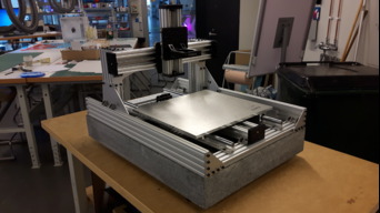
  1. linmag

    linmag Well-Known
    Builder

    Joined:
    Nov 1, 2017
    Messages:
    30
    Likes Received:
    39
    linmag published a new build:

    Read more about this build...
     
  2. amm ann

    amm ann New
    Builder

    Joined:
    Aug 11, 2017
    Messages:
    3
    Likes Received:
    0
    Keep me posted
    I'm also planning to build one same as yours
    thanks
    miney
     
  3. linmag

    linmag Well-Known
    Builder

    Joined:
    Nov 1, 2017
    Messages:
    30
    Likes Received:
    39
    Sure will, I will mainly be building this during wednesday evenings, so hopefully there will be a weekly update.
     
  4. amm ann

    amm ann New
    Builder

    Joined:
    Aug 11, 2017
    Messages:
    3
    Likes Received:
    0
    No problem Thanks
     
  5. linmag

    linmag Well-Known
    Builder

    Joined:
    Nov 1, 2017
    Messages:
    30
    Likes Received:
    39
    Yesterday I buildt the frame and parts of the X-axis to see how my modification of gantry uprights would work out.
    It was fun and fast to build everything, this kit is easy to put together. I think I've spent 3 hours in total so far and the mechanical part from the kit is almost completed. The fact that all my extrusions came in exact lengths helped to speed things up. Everything seems to be of really good quality, which makes me very happy
    I only needed to file down the "tabs" from the casted angles, otherwise it was like a Lego kit.
     

    Attached Files:

    #5 linmag, Feb 8, 2018
    Last edited by a moderator: Mar 7, 2018
  6. linmag

    linmag Well-Known
    Builder

    Joined:
    Nov 1, 2017
    Messages:
    30
    Likes Received:
    39
    My first idea was to have the XL gantry plates for X and Z axis, where the Z C-beam is flipped, but after building most of the machine I’m having second thougts. I want the X axis sitting as low as possibly for rigidity, and with the original setup the spindle and tool can be lifted above the bottom of the Z C-beam (compared with flipped Z C-beam, the tool will always protrude below the bottom of the Z C-beam, making me to need taller gantry for the same thickness of material to cut). Therefore the original setup seems better.

    Have not decided yet, but leaning towards the original Z setup.
     
  7. linmag

    linmag Well-Known
    Builder

    Joined:
    Nov 1, 2017
    Messages:
    30
    Likes Received:
    39
    Yesterday I completed the original build, and tested the looks with 700 mm SBR16 rails. Since I would like to have an enclosure for the machine I decided to order two new side pieces in the length of 750 mm, and use the original sides as new supports inbetween the sides. And by limiting the Y axis travel to 370 mm (to fit within the enclosure) I could aswell use my spare XL gantry plate in the Y axis.
    Hopefully the new aluminum extrusions will arrive before next wednesday.
     

    Attached Files:

  8. linmag

    linmag Well-Known
    Builder

    Joined:
    Nov 1, 2017
    Messages:
    30
    Likes Received:
    39
    This week there is not that much of an update since I'm still witning for my new 750 mm extrusions. Meanwhile I have talk to people more experienced than me, and they have talked me into to just use the nut block in the Y axis. It would be more difficult to set up three linear guides (C-beam and two linear rails without binding) and without any real need.

    Other than that, I have been 3D printing a dust shoe and spacers to fit Makita with the Open builds router mount.
    The dust shoe I found here on Open builds (Scotty Orr - https://openbuilds.com/threads/makita-rt0701c-dust-shoe.10418/, and https://openbuilds.com/projectresources/spindle-mount-adapter-for-makita-rt0701c.268/)
    [​IMG]

    I also laser cut a test piece of the work table in the size 370 x 370 mm to get a visual of the end result. On the picture it is not raised to fit above stepper motor as if should be in the end .
    [​IMG]
     
    Mark Carew likes this.
  9. linmag

    linmag Well-Known
    Builder

    Joined:
    Nov 1, 2017
    Messages:
    30
    Likes Received:
    39
    No uppdate this week since I’m still waiting for my last pieces.
     
  10. Prometheus

    Builder

    Joined:
    Mar 21, 2015
    Messages:
    17
    Likes Received:
    0
    @linmag , Where were the Y side rails and sliders purchased? They seem to be robust.
     
  11. linmag

    linmag Well-Known
    Builder

    Joined:
    Nov 1, 2017
    Messages:
    30
    Likes Received:
    39
    #11 linmag, Mar 1, 2018
    Last edited: Mar 29, 2018
  12. linmag

    linmag Well-Known
    Builder

    Joined:
    Nov 1, 2017
    Messages:
    30
    Likes Received:
    39
    The 750 mm extrusions finally arrived, and I have modified the frame to new dimensions.
    Next up will be to look into attaching the SBR16 rail and the moving bed.
    [​IMG]
     
    GrayUK and spirre like this.
  13. linmag

    linmag Well-Known
    Builder

    Joined:
    Nov 1, 2017
    Messages:
    30
    Likes Received:
    39
    I would like to add some weight to the machine (always good with weight). Has anyone tried to bolt the machine to a granite slab? Or a really heavy work bench?
     
  14. linmag

    linmag Well-Known
    Builder

    Joined:
    Nov 1, 2017
    Messages:
    30
    Likes Received:
    39
    So this week I started with the SBR16 rail and discovered that one of them were really bent (like 1.5 mm). Got really frustrated that I havent check this before... However after removing the rod from the support I could see thet the rod was straight, and the support bent. First I contacted the seller and we will see what happends with my complaint (bought it from China at low price). Secondly I used some brute force to try to straighten the support by clamping it in opposite direction. First with 6 mm shim, but it was not enough. Then with 12 mm, and finally with 18 mm shim did the trick. And by varying the position of the clamps it seems that I got it fairly straight of the length of the rail. After mounting the rod back everything looks pretty good, this could be good enough.
    Next week I can look into fastening them to the frame.

    Picture with the most extreme clamping :)
    [​IMG]
     
  15. Gary Caruso

    Gary Caruso OpenBuilds Volunteer
    Staff Member Moderator Builder

    Joined:
    May 19, 2016
    Messages:
    1,183
    Likes Received:
    530
    How would this help?
     
  16. linmag

    linmag Well-Known
    Builder

    Joined:
    Nov 1, 2017
    Messages:
    30
    Likes Received:
    39
    Reduce vibrations
     
  17. linmag

    linmag Well-Known
    Builder

    Joined:
    Nov 1, 2017
    Messages:
    30
    Likes Received:
    39
    Have not buildt that much lately, except for drilling new holes in the SBR16 rail and bolted it to my machine. I also adjusted the position of the gantry to get the router bit at the centre. (The back of the gantry uprights is 143,5 mm from the back end of the 750 mm extrusion.)

    But I have found a nearby company that are selling ganite kitchen slabs. And they could make me a granite slab of size 760x550 mm with holes to bolt my machine firmly to the slab. The granite slab will be sitting on three feets so the (possibly) not flat surface below will not be able to introduce deflction to the machine.

    [​IMG]
    [​IMG]
     
    #17 linmag, Mar 29, 2018
    Last edited: Mar 29, 2018
    GrayUK and spirre like this.
  18. linmag

    linmag Well-Known
    Builder

    Joined:
    Nov 1, 2017
    Messages:
    30
    Likes Received:
    39
    My granite slab has arrived. Size 760x550 mm and 100 mm thick, with an approximate weight of 70 kg, this thing is solid. On the picture the machine is just sitting on top of the slab, still need to fasten bolts so that I can fasten it, and also get three feets for it.
    [​IMG]
     
  19. GrayUK

    GrayUK Openbuilds Team Elder
    Staff Member Moderator Builder

    Joined:
    May 5, 2014
    Messages:
    1,668
    Likes Received:
    627
    Looking Good linmag, however, the words, sledgehammer and nut, come to mind. :D
    Your not taking any chances then. :D:rolleyes:
    That definitely isn't going to warp!! :thumbsup::thumbsup::thumbsup:
     
  20. linmag

    linmag Well-Known
    Builder

    Joined:
    Nov 1, 2017
    Messages:
    30
    Likes Received:
    39
    I know. Actually, I was a bit surprised when I got it that thick. We talked about a kitchen desk slab, but I guess they liked the idea to build a CNC and upped the spec.
     
  21. linmag

    linmag Well-Known
    Builder

    Joined:
    Nov 1, 2017
    Messages:
    30
    Likes Received:
    39
    Feels like the stone is telling me to build a more serious machine
     
  22. GrayUK

    GrayUK Openbuilds Team Elder
    Staff Member Moderator Builder

    Joined:
    May 5, 2014
    Messages:
    1,668
    Likes Received:
    627
    I think you have a pretty serious, and good looking, machine there anyway. :thumbsup:
    My next machine is going to be very similar to yours, except I will use Linear rails on the X and Z axis' as well.
    I want to eliminate wheels altogether, as I feel they are a weak point on a solid construction and rails are much easier to set up. :D
    Can't wait for the first cut video. :)
    May The Chips Fly For You!! :D
    Well done. :thumbsup::thumbsup:
     
  23. MaryD

    MaryD OpenBuilds Team

    Joined:
    Apr 13, 2016
    Messages:
    649
    Likes Received:
    639

    Things just got serious alright. :jawdrop: That is an awesome piece of granite. Bit too big for the spoiler board that I was imagining. :ROFL:
     
  24. linmag

    linmag Well-Known
    Builder

    Joined:
    Nov 1, 2017
    Messages:
    30
    Likes Received:
    39
    Before I started this build I have been thinking about welding a steel frame and using linear rail. But the one thing keeping me from getting started was that I did not have a solution on how to get all axis perpendicular and all rails per axis in the same plane due to warping when welding.

    I settled for a C-beam kit to get going quick, and to stop to just build my steel frame machine in my head. But, as you GrayUK, I have thought a lot about changing to linear rail on all axis. But decided not to, since I’m trying to keep cost down. I could always upgrade X and Z axis further down the line.

    But had I known that I could score this granite slab I think I would have buildt the steel frame anyway.
    (But it will also sit nicely under the C-beam machine )
     
    GrayUK likes this.
  25. wiremonkey

    Builder

    Joined:
    Mar 23, 2017
    Messages:
    40
    Likes Received:
    12
    HOLY GRANITE!
     
  26. GrayUK

    GrayUK Openbuilds Team Elder
    Staff Member Moderator Builder

    Joined:
    May 5, 2014
    Messages:
    1,668
    Likes Received:
    627
    Hey linmag.
    How's that build of yours going????? :rolleyes:
     
  27. linmag

    linmag Well-Known
    Builder

    Joined:
    Nov 1, 2017
    Messages:
    30
    Likes Received:
    39
    Well, I got hold up with sourcing some parts (actually, I had a hard time finding rubber feets since my granite slab is soo thick).
    I'll post an update soon :)
     
    GrayUK likes this.
  28. amm ann

    amm ann New
    Builder

    Joined:
    Aug 11, 2017
    Messages:
    3
    Likes Received:
    0
    Thanks linmag,
    been reading and observing closely. Cannot wait for the first cut video.
    BTW can you give me the link to where you bought your CNC rails etc?
    thanks again.
     
  29. linmag

    linmag Well-Known
    Builder

    Joined:
    Nov 1, 2017
    Messages:
    30
    Likes Received:
    39
    Soo, here is an update. I have:
    - 3 Rubber feets bolted to the granite.
    - Glued bolts to the granite to be able to bolt down the machine to the granite.
    - Cut aluminum angles for bolting down (still need to drill holes and mount)
    - 10 mm aluminum "work table" in dimension 410x375 mm (actual working area will be about 375x375 mm). Still need to drill holes for the carriges for the SBR16 rail and the lead screw nut.
    - Changed the orginal Z-axis plate to XL gantry plate (I will still have more travel on the Z-axis than the maximum thickness of material (which will be 95 mm)).
    - WaterJet cut some extra brackets for stiffening the machine. (I got the chance to learn to use a waterjet cutter, and had to have something to practice on. So I did some extra brackets for the gantry, the frame and for stepper mounts in 3mm steel. And some mounting plates for micro limit switches in 2mm alu. I hope they will fit, since I did the drawings in a hurry. :)

    Pictures can be found in the build log.

    It will be a while to the next update, since it's summer and I'm spending my time with my family. Perhaps I will do something, and if so, I'll post an update.

    Cheers.
     
    GrayUK likes this.
  30. linmag

    linmag Well-Known
    Builder

    Joined:
    Nov 1, 2017
    Messages:
    30
    Likes Received:
    39
    Okay, so I got around to build some.
    I have painted the steel plates silver.
    And I have rebuildt the machine with the new plates, both the plates for stiffening the joints, and the plates for makeing the stepper motors to be mounted with four anchor points.
    Here is a picture of the end result - more pictures can be found under the build tab.
    [​IMG]
     
    MatthewQ likes this.

Share This Page

  1. This site uses cookies to help personalise content, tailor your experience and to keep you logged in if you register.
    By continuing to use this site, you are consenting to our use of cookies.
    Dismiss Notice