How to convert your C-beam Machine to Modesty
Below you will find a bill of materials needed to modify a C-beam Machine to Modesty, and also some information why I did some of my choices.
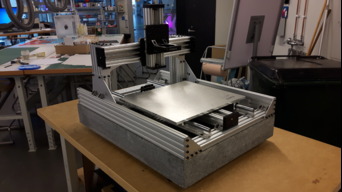
![[IMG]](https://openbuilds.com/attachments/build5_4_small-jpg.31103/)
Picture: Illustration of how to change the C-beam Machine to Modesty. The illustration is not according to scale.
BOM:
OpenBuilds:
+ C-beam Machine kit OpenBuilds C-Beam Machine
From this kit you remove:
- 4 pieces of 250 mm 20x60 V-Slot® 20x60 Linear Rail
- V-slot gantry plate - Universal V-Slot® Gantry Plate - Universal
- Build plate Build Plate
From OpenBuilds you add:
+ 2 pieces of 300 mm C-beam C-Beam® Linear Rail
+ 2 pieces of 750 mm 20x60 (or 20x80) V-Slot® 20x60 Linear Rail
+ 2 pieces of XL gantry plate XLarge C-Beam Gantry Plate
+ 14 pieces of casted corners Cast Corner Bracket
+ 28 T-nuts Tee Nuts - M5 (10 Pack)
+ 28 8mm M5 Low profile screws Low Profile Screws M5 (10 Pack)
From somewhere else:
+ 2 pieces of 700 mm SBR16 linear rail
+ 2 pieces of 250 mm HGR15 mm square rail
+ 2 pieces of 500 mm HGR15 mm square rail
+ 1 granite slab to bolt the machine to, size 760x550 mm, weight 110 kg.
+ 1 10mm aluminum plate, size 410x375 mm
+ 1 glue for the bolts in the granite slab
+ 3 rubber feets
+ 13 extra brackets for stiffening the machine (see dxf in files section)
+ 1 40 cm aluminum angle cut in 2 pieces 50 mm, 2 pieces 60 mm and 2 pieces 90 mm to make fastening to the granite slab.
Note: If you file down the tabs on the casted corners, you should use 8 mm M5 screw instead of 10 mm. If you do this you will need more 8 mm screws.
Choosen setup:
Base: I have choosen to bolt my machine to something rigid and heavy, and it will be a granite slab of the size 760x550 mm. The machine will be bolted firmly to the granite base to reduce vibrations, and the granite base will be standing on three feets (to not introduce deflection from the surface it is standing on not beeing perfectly flat).
Frame: I have changed the uprights in the gantry to two pieces of 300 mm C-beam, instead of the four pieces of 250 mm 20x60. I have also decided to extend the frame i Y direction to 750 mm (since I use 700 mm linear rail), and limit the Y travel to 370 mm. I was thinking about maximizing to 450 mm since I'm only using the nut block, but choosed to limit it to 370 mm. This will give me the opportunity to make an encosure attached to the C-beam machine frame without the table travel to hit the enclosure. I have ordered two new pieces of aluminum extrusion in 750 mm length for the sides. I will use my two extra spares of 20x60 (from the sides) to attach in between the (new) sides, and also to give the SBR16 rail a more rigid attachment.
Z axis: I have choosen to use square rail for the Z-axis. The Z travel seems to be 95 mm (not really sure yet how I will chose to do with the hight of the maching bed).
X axis: I have choosen to use square rail for the X-axis. - gives approx 375 mm of travel.
Y axis: For the Y axis I will only use the nut block (no gantry plate) and 700 mm SBR16 linear rail. The table will be raised a bit to clear the Y stepper motor, and have approx 375 mm of travel.
Control: Plan A): (5 years old) I will control it by using a RPi running bCNC -> Arduino Nano running GRBL -> TB6600 stepper drivers -> 425 oz steppers driven by 40V power.
Plan B): Will need to reconsider the options of today, especially the software/control. Perhaps a ESP32? I guess I'll also keep the TB6600 drivers and 425 OZ steppers in plan B.
Spindle: The spindle will be a Makita RT0700/0701 (10.000 - 30.000 rpm), and use a precision collet 1/8" from German company CNC_PLUS.
Build log in pictures:
Picture: First I buildt the original kit (with C-beam gantry uprights).
![[IMG]](https://openbuilds.com/attachments/80232129-a1c6-4fa1-8750-125029a54945-jpeg.31793/)
Picture: Then I rebuild with new 750 mm sides.
![[IMG]](https://openbuilds.com/attachments/82c4e425-4036-413e-868b-d9cd702dd9c1-jpeg.31831/)
Picture: Frame done.
![[IMG]](https://openbuilds.com/attachments/eecc6142-661f-4707-9a35-3a840dcf686c-jpeg.31832/)
Picture: Back view.
![[IMG]](https://openbuilds.com/attachments/5f00dbaf-ef1b-4a4c-b7a2-a9f7f361f111-jpeg.31833/)
Picture: Front view with SBR16 rail.
Picture: The frame is now completed (750 mm long i Y-direction). However the SBR16 rail and working table needs some work.
![[IMG]](https://openbuilds.com/attachments/de575cb6-007f-49e6-8b12-7334a18f62e4-jpeg.31790/)
Picture: Side view.
![[IMG]](https://openbuilds.com/attachments/4e390a0e-6217-45b4-8b08-99ca77522c4b-jpeg.31791/)
Picture: Front view.
![[IMG]](https://openbuilds.com/attachments/build7_2-jpg.32016/)
Picture: Unfortunatly one fo the SBR16 rails were bent (only support not the rod). So here I am trying to straighten the bent support, first with 6 mm shim, then 12 mm and finally...
![[IMG]](https://openbuilds.com/attachments/build7_4-jpg.32017/)
Picture: ... finally 18 mm shim did the trick. And by varying pressura points I got it straight for all the length.
![[IMG]](https://openbuilds.com/attachments/build7_5-jpg.32018/)
Picture: Flat and straight SBR16.
![[IMG]](https://openbuilds.com/attachments/build8_1-jpg.32330/)
Picture: Drilling new holes in the SBR16.
Picture: The SBR16 bolted to the machine., and position of the gantry adjusted to have the router bit at the centre of the machine.
Picture: I finally got hold of my granite slab base.
Picture: The machine placed on top of the granite slab base. 100 mm thick and with a wheight of 110 kg.
Picture: The 3 rubber feet bolted to the granite slab.
![[IMG]](https://openbuilds.com/attachments/build10_2-jpg.33784/)
Picture: Glued bolts to the granite to be able to bolt down the machine to the granite.
Cut aluminum angles for bolting down (still need to drill holes and mount).
![[IMG]](https://openbuilds.com/attachments/build10_3-jpg.33785/)
Picture: 10 mm aluminum moving bed in dimension 410x375 mm (actual working area about 375x375 mm). Need to drill holes for the carriges for the SBR16 rail and the lead screw nut. It is also barely visable in this picture that I changed the original Z-axis plate to an XL Gantry Plate.
Picture: Water Jet cut some extra brackets for stiffening the joints in the gantry and frame, and for stepper mounts - all in 3mm steel.
Picture: And I also cut out some mounting plates for micro limit switches in 2mm alu.
Picture: Rebuilding the gantry a) - two new plates mounted partly.
Picture: Rebuilding the gantry b) - all three plates mounted, as well as new stepper mount.
Picture: Rebuilding the gantry c) - new view.
Picture: Rebuilding the gantry d) - new view.
Picture: Machine overview, also note new corner plates.
Picture: The mounts to the granite slab has been drilled and bolted into place.
Picture: A new and solid table for the router to sit on has been buildt. You can also see a bed made out of Corian mounted in the picture.
Picture: Mounting of square rail.
Picture: Milling the surface flatter for the linear rail (did have some binding previously).
Picture: Mounting new aluminum plate 10mm thick.
Picture: Mounting new aluminum plate 10mm thick and new router mount.
About the build:
I chose to build the C-beam Machine since it seems to be fairly rigid and accurate, and the size fits my needs. I have been thinking about to build a CNC machine for a while, and decided that 2018 is the year it will happend.
I read about some of the C-beam builds before ordering my kit, and decided to change the uprights of the gantry to C-beam as Metalguru had done in 'Improved CBM' build. I also read about how to improve the rigidity of the moving bed, in both Metalguru's build as well as Dogmeat's 'Custom C-Beam XL' build (really neat solution). At first I thought that I could first settle for a simplier solution, and improve over time, but... I decided to go for it in the first try, hence I chooce linear rail. This since I figure that after proper alignment of all the axis I do not want to take the machine apart more than I need. I’m also thinking of a simple rubber shield to prevent the chips from ending up inside the Y axis C-beam and into the linear rail.
So I was able to change the 4 pieces of 20x60 to 2 pieces of 300mm C-beam for the uprights of the gantry in the order, and also added 2 pieces of XL gantry plates. I have also ordered 2 pieces of 700mm SBR16 rail for table support. The table will be raised a bit to clear the Y stepper motor. And in the middle of the build I added longer frame in the Y direction, and ordered two pieces of 750 mm aluminum extrusion.
My first idea was to have the XL gantry plates for X and Z axis, where the Z C-beam is flipped, but after building most of the machine I’m having second thougts. I want the X axis sitting as low as possibly for rigidity, and with the original setup the spindle and tool can be lifted above the bottom of the Z C-beam (compared with flipped Z C-beam, the tool will always protrude below the bottom of the Z C-beam, making me to need taller gantry for the same thickness of material to cut). Therefore the original setup seems better.
To give the machine a firm base to be bolted to and to reduce vibrations, I decided to either get a heavy work bench or something else. Then I got the recomendation to use a granite slab, found a nearby company making grave stones and kitchen slabs, and bought a piece. 100 mm thick with a weight of 110 kg this thing i solid.
I'll post updates here and in the discussion as I go along.
C-beam Machine - Modesty
Build in 'X/Y Table Style CNC Mill' published by linmag, Mar 18, 2024.
Modified C-beam Machine. Taller (30 cm) C-beam uprights in gantry, and longer 750 mm frame in Y direction. XL gantry plate on X (and Z?). Y will have additional 700 mm SBR16 rails as extra support and slightly raised bed to fit above stepper motor. Approx. machinable area of 370 x 370 mm.
-
-
Build Author linmag, Find all builds by linmag
-
- Loading...
-
Build Details
- Build License:
-
- CC - Attribution - CC BY
Inspired by
MetalGuru - Improved CBM -
Attached Files:
-


