Welcome to Our Community

Some features disabled for guests. Register Today.

Add more V-Slot to my Makerfarm 10" Prusa i3v

Discussion in '3D printers' started by David Bunch, Sep 30, 2019.

  1. David Bunch

    David Bunch Veteran
    Builder

    Joined:
    Oct 27, 2014
    Messages:
    624
    Likes Received:
    432
    David Bunch published a new build:

    Read more about this build...
     
    cheaplicenseshop likes this.
  2. MaryD

    MaryD OpenBuilds Team

    Joined:
    Apr 13, 2016
    Messages:
    649
    Likes Received:
    639
    How were the prints BEFORE the upgrades?
     
  3. David Bunch

    David Bunch Veteran
    Builder

    Joined:
    Oct 27, 2014
    Messages:
    624
    Likes Received:
    432
    The prints have not changed much from the upgrade. Think I did get rid of a little bit of the ringing in the prints. I also upgraded to a bigtreetech SKR V1.3 32bit board with TMC2208 on x & y & LV8729 on the Z & Extruder. The new front & back plates with the 2020 V-slot does make it a lot more sturdy & less vibration. I have some cork gaskets for the motors & will probably add one to the Y-axis motor first to see if that makes a difference.
     
    cheaplicenseshop likes this.
  4. David Bunch

    David Bunch Veteran
    Builder

    Joined:
    Oct 27, 2014
    Messages:
    624
    Likes Received:
    432
    I was looking at Makerfarm's option for upgrading the i3v to their Pegasus version which has the V-slot frame around it, but I don't really want to spend the $165 for the upgrade since I really only need the V-Slot parts which I already have. I took a look at their manual & saw an angled plastic part to connect the top V-slot to the angled V-slot support to the back like a number of machines of this similar design use. I had already sketched in 2D of doing this style support, so I started drawing this up in 2D, then put it in openscad with variables. Since I don't know what my angle will be for this, I made that variable along with some of the other widths. This connects a little different than the Pegasus & it will probably change. I was also looking at this neat V-Slot Hinge that openbuilds has. Adjustable V-Slot Hinge Here is a screen shot of that design. I need to put more of the V-slot together in openscad before printing as I might want to connect 90 degrees to what one of them is. Once I get it closer to what I want, I will put it in fusion 360 since I can smooth out the sharp edges a little easier. I have to get my Folgertech Kossel changed over to the 32bit board before I do anymore work on this.
    V2020_Ang_Connect_Rev5.jpg
     
  5. David Bunch

    David Bunch Veteran
    Builder

    Joined:
    Oct 27, 2014
    Messages:
    624
    Likes Received:
    432
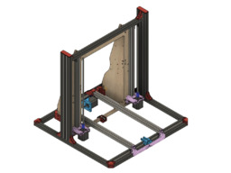
    Doesn't look like I need to add that angle bracket I showed in my previous message. I got my Kossel printer back up & running on new 32bit board, so I am getting back to this project. After Test fitting some V-Slot around the machine, think I came up with a solution with minimum changes to the design & no cutting of V-slot since 500mm fit nicely. I leave the Wood frame in place & build the frame around it. I have already added the top 2020x500mm & changed the front to a 2040x500mm. I had to raise the front belt idler tensioner up with one washer to clear the V-slot. I needed to change the back plate to use 240x250mm instead of the 2020 in order to get a 2020x500mm connected behind that, so I changed the wood connection parts & will have to use single plastic connectors for 2020 V-Slot that the Y-bed rides on. I could use standard metal corner brackets for all the V-Slot connections, but I do not have enough, so I will design some plastic one & see if that is enough to make this machine more rigid. I pieced all the parts together in fusion 360 before printing any parts to see if I missed something. Looks like it should work. The 2060 for the verticals is probably overkill, but I am using the V-Slot I have on hand. Here is a screen shot.
    i3v_PerimeterFrame.jpg
     
  6. David Bunch

    David Bunch Veteran
    Builder

    Joined:
    Oct 27, 2014
    Messages:
    624
    Likes Received:
    432
    While waiting on some prints I designed this specialized corner part that will go between the Front & Side bottoms. I will only use one of the M5 end holes. Not sure there is enough clearance for both screws. Fusion 360 makes this easy. I can put a design together a lot faster with this software rather than my previous workflow of Draftsight for 2D & openscad for final 3D. I still use the latter 2 softwares for some things.
    V2020_90_Front.jpg
     
    #6 David Bunch, Oct 9, 2019
    Last edited: Oct 10, 2019
  7. David Bunch

    David Bunch Veteran
    Builder

    Joined:
    Oct 27, 2014
    Messages:
    624
    Likes Received:
    432
    Here is another cute corner I made for the back. My printer jammed on printing my 2nd wood connector on the back, so I have to fix that before I can print again or I might try printing them on my Delta. This connector requires 2 t-nuts & one screw is threaded into end of v-slot.
    V2020_90_Back.jpg
     
  8. David Bunch

    David Bunch Veteran
    Builder

    Joined:
    Oct 27, 2014
    Messages:
    624
    Likes Received:
    432
    I cleared my extruder jam which wasn't too bad. I printed one of the smaller corners to test before printing a 2 hour print. The backplate (1st image) that connects the 2 y-axis V-slot that the build plate rides on I was going to make separate parts since I changed this V-Slot from a single 2020 to a 2040,2020 combo, but it does make it a lot easier to put together with both sides connected. This morning I came up with an idea to keep it one part & also make it the connection plate between the 2040x250mm & the 2020x500m V-slot. Looks like that will be a 3 hour print. I will print it on the angled side so it requires no support. Using this to connect to the 2020x500mm also saves me 2 screws & t-nuts since I was going to use a simple joining plate to connect these 2 V-Slots. I count 26 T-nuts for this upgrade. Think I have all the parts for my upgrade into Fusion 360. I discovered one problem when putting the parts in the assembly & that was the P/S side Wood connector was going to interfere with the new Backplate connector. I could have shifted the back 2040x250mm a little more towards that bracket, but that would have made the other side a longer reach. I ended up cutting a little recess cave for that part to slide in. This looks like it should not affect the strength of that connection. You can see this recess in the 1st image. I also updated the build icon the 2nd attached image. This upgrade currently uses the following V-Slot:
    1-2040x500mm Front
    1-2040x250mm Y-axis Back
    4-2020x500mm Far Back, Bottom Sides & Top
    2-2060x500mm Vertical Sides
    Y_Back_Solid10_V2020_Connect.jpg i3v_PerimeterFrame_V2.jpg
     
  9. David Bunch

    David Bunch Veteran
    Builder

    Joined:
    Oct 27, 2014
    Messages:
    624
    Likes Received:
    432
    I was playing with making the corner parts more parametric in fusion 360 using more variables & tying down the dimensions. I added the fusion 360 file for this, in the files area as Corner_60mm v2.f3d along with Corner_30mm.stl, Corner_60mm.stl & Corner_30mm.stl files in case someone wants to play with this design some. If you change any of the variables & making it shorter than 43mm Len or Ht you should change the Side_Rad & Side_Offset first to keep the geometry from going wacky. This files uses 2 holes, but if you want to use just 1 or add another, just change it in the 2 affected sketches & extrude them again along the timeline history. The other variables to change as I mentioned in previous sentence are Len & Ht. The Ht variable I have set to Len, but that can be changed to a different dimension if desired. The Thk variable is the thickness of plastic where M5 screw goes thru. M5 variable is diameter of M5 screw Hole & there are a few other miscellaneous variables you can play around with. The 30mm plastic corner I printed seems like it should suit my needs, but I may try the other sizes later. Here are 3 images that show those 3 sizes compared to the black angle metal corner which you can buy. I test fit 2-30mm corners on & it feels pretty sturdy after tightening screws all the way down.

    Corner_30mm.jpg Corner_60mm.jpg Corner_90mm.jpg

    While test fitting one side, a 2020 base & 2060 vertical on the side I noticed a potential interference problem with the X-axis motor assembly or it will be a very small clearance. After placing that same part on the other side to look for problems there, looks like I can just shift the frame more towards the x-motor side since I have plenty of clearance on that side & there is nothing tied to that frame that won't let me shift it that way.

    The more I look at this design, the more I find something I can change. Looking at what is still connected to the wood, it is only the motor mounts & the 2- 2020 Z-axis V-Slot. I was looking at how to connect those to the side vertical 2060x500mm V-slot & realized it is 500mm across the width of that middle section to connect to both 2060. The only problem I just noticed is the y-axis 2020's are only 30.7mm above the bottom frame. I wanted to use a 2040 across there, but 2020 would work. I could make the y-axis end connectors higher up to clear that & be able to use 2040, but using the 2020 sounds simpler & probably more stable. I will think about that after completing my current upgrade version. I could still use the 2040 or any other 20xx, but lay it down so the 20mm is the height.
     
    #9 David Bunch, Oct 11, 2019
    Last edited: Oct 11, 2019
  10. David Bunch

    David Bunch Veteran
    Builder

    Joined:
    Oct 27, 2014
    Messages:
    624
    Likes Received:
    432
    I got it all put together today & it feels a lot more sturdy. It fits well & test cube print has less ringing in it. The only part that does not fit well were the front corners & I thought might be a problem. It is about 17mm extra space. I will just design a corner to fit the space later. It is only a cosmetic issue for now. Here are some photos. I needed 2 more T-nuts so I used a couple of drop in T-nuts that I had. You can never have enough T-Nuts. I shifted the frame 15mm towards the X motor from my original dimensions & I have exactly 15mm clearance on that motor. All & all I am happy with this upgrade. I started working on a Z motor mount in order to get rid of wood all together, but will leave it alone for now. I could probably print higher now by changing the 400mm lead screws & 2020 verticals to 500mm, but I very seldom wish I could print taller. I do sometimes wish I had a 12" print bed.
    IMG_9165_900x600.jpg IMG_9166_800x600.jpg IMG_9163_800x600.jpg
     
  11. David Bunch

    David Bunch Veteran
    Builder

    Joined:
    Oct 27, 2014
    Messages:
    624
    Likes Received:
    432
    Now that I have the external frame pretty much the way I want, I am looking at other things to improve on this printer. I have been having some extruder issues, so I started working on designing a X-carriage with the pancake motor mounted against the plate as I have seen other designs do. This will allow me to change it from a Titan to a BMG to see if that is better. I have a drag chain currently connected to the front of the extruder & snaking out along the Y-axis. At the time that was the easiest way to do it without redoing the X-carriage. Now that I am redoing this. I am connecting it to the top. I connected all the affected parts into the fusion 360 assembly, so looks like it should work. I initially had the drag chain centered on the 2020 top X-axis, but moved it 2mm in to give a little more clearance on the M8 Lead screw. I am using the openbuilds 500mm length drag chain for this. Here are 2 screen shots of what the design currently looks like. One from the Front & one from the Back.
    Titan_BMG_ExtruderMount_Front.jpg Titan_BMG_ExtruderMount_Back.jpg
    I ordered that book that openbuilds mentioned recently, "Designing 3D Printers" & it should be here today. The price dropped a little over $9 for that book since I looked at it a week or so ago. Thanks openbuilds for pointing out this book.
     
  12. David Bunch

    David Bunch Veteran
    Builder

    Joined:
    Oct 27, 2014
    Messages:
    624
    Likes Received:
    432
    I have been working on cleaning up my shed this week so I can cut some aluminum plate on my Sphinx CNC to replace the wood/plastic parts on the X-axis parts on my 3d printer. I plan to use trochoidal milling in Estlcam for this. I have not cut aluminum before so this will be a new experience for me. I have a couple of 1/8" single flute spiral upcut mills I plan to try 1st. Here are the profiles I made & they are based on plastic parts I have already used on the machine, so they should work. I did change the hole diameter of the holes to a little smaller than I did for the plastic since the metal should be a lot better tolerances on these. I have some 1/8" & 1/4" T6 6061 aluminum sheets to use. From what I have seen on other machines, the 1/8" should be sufficient for these so I will use that 1st. The 1/8" sheets are 12"x24", so I will need to cut them in half before using them. I could cut them on my table saw since I have the correct blade for that, but I think that will be too messy. I will see if I can cut it in half on the CNC. I was originally thinking I could use a hack saw, but a friend reminded that it would be too short for that 12" cut.
    Alum_X-Axis_Plates.jpg
    I added a back plate for the X-carriage this week to make that carriage more sturdy. Seemed like the plastic front carriage has a tendency to flex a little, but the back plate it does not. I lost a little build space in the X-axis with this as the top back plate hits the wood X-Axis motor mount, but I will get that back when I move to aluminum for that carriage.
    IMG_9227_800x600.jpg
    It was good that I changed that carriage as I noticed some fraying on the hotend heater cable. This happened over the course of a few months because I had not used any covering where the wires went into the cable chain. I have since fixed that & won't make that mistake again. I ordered a replacement E3D V6 hotend in case I need to change that out, but I realized I could just tape that wire with kapton tape. I have temporarily removed the cable chain until I finish taking the rest of the wood off the machine.
    IMG_9228_800x600.jpg IMG_9230_800x600.jpg
    In preparation of taking all the wood off this machine, I mounted the Electronics to the back of the 2060 vertical I have on that side. I will make it look a bit nicer after getting the wood out of the way. I didn't move the P/S off of it yet & may just leave that resting on the table while I figure out a spot for it on the new upgrade.
    IMG_9233_800x600.jpg
    I have always put the hotend fan attached directly to 12v & was getting frustrated in trying to get the P/S 12v wires & those 2 wires to go in that same hole. It had worked before, but was being difficult this time. I had read of way to hook this up differently a while back but did not pursue it at the time. After some google searching, I found a way to connect that works great for me. I have it hooked up to the E1 heater as per a comment in this thread. SKR 1.3 Fan Setup : ender3

    #define E0_AUTO_FAN_PIN FAN1_PIN
    #define EXTRUDER_AUTO_FAN_TEMPERATURE 40 //This is usually 50, but I lowered it a little
    IMG_9235_800x600.jpg
    I still have to get used the printer being on now when the hotend is cool since it very quiet without that fan.
     
    Peter Van Der Walt likes this.
  13. David Bunch

    David Bunch Veteran
    Builder

    Joined:
    Oct 27, 2014
    Messages:
    624
    Likes Received:
    432
    I am printing the Z-axis motor mounts today which is the last parts I need to actually print to take the wood frame out of the mix. Those mounts do not go all the way to the bottom of the 2020 verticals, so I made printed a couple of spacers so they are both set at the same height. The most vibration I am feeling on the printer which is not much is on the verticals. After I have the wood frame out, I will look into putting a 2020x250mm v-slot on each side towards the back. I will have to design a special angled connector for that. I also realized that after I take the wood frame out, I only need a 2020x500 or 2040x500 in the back & that should allow me to put 500mm lengths around the base all lined up on the corners with no special connectors. This is really working out well so far. Next time I order from openbuilds I will get some metal corners as they should make the frame stronger with not that much extra cost. I will see how my angled 2020's in the back work first.
     
    Peter Van Der Walt likes this.
  14. David Bunch

    David Bunch Veteran
    Builder

    Joined:
    Oct 27, 2014
    Messages:
    624
    Likes Received:
    432
    After spending too much time filing the plastic on a Z-axis motor mount to fit the vertical 2020 v-slot, I did some more test prints of a smaller part. I made it a .3mm clearance around the V-Slot. I still might have to file it just a little to fit, but should work. Originally I was only having the part connected on 2 sides of the V-slot & then thought I would add a 3rd inside edge with one M5 hole. I may only use just one M5 on each side after I see how it feels. I also added a 1mm round at each sharp inside corner since my 3d printer does not give a sharp corner so will be less to file. In the slicer I am using variable layer height to cut down on print time with .2mm where horizontal holes are & .3mm for the rest with 50% gyroid & 4 perimeters. I was also thinking that 3rd side connection to the v-slot would distribute any vibration over a larger area. I also pondered having it connect all around, but thought that was too much. I also made sure I had enough clearance to put a M5 screw on the inside where the motor is close to it by making that wall 4mm thick instead of the 6mm I used for other 2 side wall connections to the V-Slot. The screws I have would have fit with 6mm wall there, but decided to go with 4mm. Here is what it looks like in the Prusa slicer. These are coming out to be about 2 hour prints each.
    Z_MotorMount_LtRt.jpg
     
    Peter Van Der Walt likes this.
  15. David Bunch

    David Bunch Veteran
    Builder

    Joined:
    Oct 27, 2014
    Messages:
    624
    Likes Received:
    432
    I got both z mounts printed yesterday & while looking at them this morning they didn't look perpendicular to the V-Slot. I think they are way too off to work after test fitting them. At first I thought the first layer had just pulled up on the edges. After looking at my printer for problems, I found 3. One screw on the titan extruder was loose. That was an easy fix. Eccentric wheel on wooden x-axis motor mount was loose. That was an easy fix. The eccentric wheel on x-axis plastic idler was loose & I couldn't get that one to adjust completely. It might be good enough to get the print I need, but I figured this is just forcing me to make the metal plates sooner than I was going to. I needed make the plates I had a little shorter so it would be easier to clamp on my CNC. Since I did not want to have aluminum shavings all over the shed, I took the wood frame dust cover I made for my sphinx CNC & put it around my Kobalt 7" sliding miter saw with 20"x30" foam core on the outside of frame except the front to cut from. Dollar store has that foam core for $1 each. I used painters tape to tape the foam core in place. I cut one of the 1/8"x12"x24" down to about 4-6"x12" pieces, the 1/4"x12"x12" in half & the other 1/8"x12"x24" into 2-12"x12" pieces. That saw has a 7" cut width, so I just flipped it over to cut the rest of it. Also I have a blade on their that cuts copper or aluminum. This dust cover worked quite well. I had very little debris outside that frame. Here are some photos.

    IMG_9259_800x600.jpg IMG_9262_800x600.jpg IMG_9267_800x600.jpg IMG_9268_800x600.jpg
    Since I knew the C-beam was square, I put that between the 2 Z mount parts to see how much out of square the parts were.
    I have my tool paths set in estlcam & clamped a 1/8"x6"x12" ready for cutting on my Sphinx CNC & plan to cut those 3 parts tomorrow.
     
    Peter Van Der Walt likes this.
  16. David Bunch

    David Bunch Veteran
    Builder

    Joined:
    Oct 27, 2014
    Messages:
    624
    Likes Received:
    432
    I mostly fixed my problem with the printer. I had changed the pancake motor extruder mount to come off the back of as you can see from one of previous posts. The 2 screws mounting it to the top of the carriage were just a little too long & was not giving me enough threads to secure the titan extruder. I went back to my other mount & it is working much better. My 1st attempt at cutting aluminum resulted in a broken bit after a minute or so. I could see it was going to be a problem right off the bat as the bit I was using was too long & was an 1/8" shaft mounted in a 1/8" to 1/4" adapter. I ordered a Yonico 31011-SC 1/8-Inch Dia. O Flute Upcut Spiral End Mill CNC Router Bit 1/4-Inch Shank from amazon & will try that sometime this week.

    Think I have all the parts to take the rest of the wood frame out. The Z motor mounts seemed like they still were not quite vertical, so I made a slot hole for one them which will allow me to adjust this. It is not the perfect solution, but should work.
    Z_Axis_MotorMount.jpg
    I also wanted to have the P/S mounted in about the same place, so I came up with these brackets to mount it to the vertical 2020. The 1st bracket I made 50mm long, but it would have been too short where the wire connections are, so I made it about 70mm long. I am using a Meanwell NES-350-12 PS.
    PS_Vertical_2020_Bracket.jpg
     
    Peter Van Der Walt likes this.
  17. David Bunch

    David Bunch Veteran
    Builder

    Joined:
    Oct 27, 2014
    Messages:
    624
    Likes Received:
    432
    I have been looking the machine & the model over some more before taking the wood frame out as I want to have all the parts I need once I take it apart. The 12v wires & z motor wires are going across the bottom in the middle, so I designed a wire clip to hold those in place. The 2 holes are for wire ties. I might make the channel a little bigger to get some cable tubing thru there. The wood design had a connection to the center frame at the bottom of the 2 y-axis V-slots that the build plate rides on. Not sure I need anything there, but should be easy enough to design something to fit since I have the heights from the front & back connection to go by. I need to update my model some more since it is changing with the removal of the wood frame. I am not sure that P/S connected to the back of one of Z-axis Vslots will be a problem, but I can always move it later if it is.
    V2020_WireClip1.jpg V2020_WireClips.jpg
    Here is a link to the model I used for the Meanwell PS. Mine is a NES-350-12 & this one is a NES-350-27, but the dimensions I needed for reference seemed to be the same. Free CAD Designs, Files & 3D Models | The GrabCAD Community Library
     
    Peter Van Der Walt likes this.
  18. David Bunch

    David Bunch Veteran
    Builder

    Joined:
    Oct 27, 2014
    Messages:
    624
    Likes Received:
    432
    This Y-axis to bottom X middle V-slot connection turned out to be quite easy to design. Here is what I came up with & a 30 minute print for each one. I will use 2-M5 screws with T-nuts to attach it to the bottom V-Slot. The top part just rides underneath the Y-axis. I could make that top part connection like the wire clip connection in previous post, but I think this will work just as well & is simpler.

    Y2020_X2020_MidConnector.jpg
     
    Peter Van Der Walt likes this.
  19. David Bunch

    David Bunch Veteran
    Builder

    Joined:
    Oct 27, 2014
    Messages:
    624
    Likes Received:
    432
    I was thinking of taking the wood frame out today, but have a few prints I would like to do before doing this. I did see one problem of how I was going to join the vertical Z-axis v-slots to the new bottom 2020. There is not enough room to put corner brackets in since the motor mount is too low, although there does look like there is room to move those motors up enough for them. I had ordered some joining plates from Zyltech last week with their 20% off Halloween special which solved that problem. I had ordered 4 T-Brackets that work perfect as shown in the photo. I also ordered some other plates & corners to see how good they were. The 90Deg & T aluminum joining plates are a little thinner (3.6mm) than openbuilds (6mm), but should be sufficient for my use. The 4 hole T bracket attached to the 2-2020's is 2mm steel. I will not need all those parts shown in the photo, but bought the other parts for spares for another possible 3D printer.
    IMG_9272_800x600.jpg
    I am also going to change the Y-axis idler pulley to openbuilds larger one, Smooth Idler Pulley Wheel to give more clearance of the belt below the Build plate. I have to redesign the plastic front holder, so I will do that before taking it apart. I have not gotten around to cutting the x-axis aluminum plates yet which is good since I decided to change the way I was going to do the carriage. I might wait to do that after I take the wood out of the picture to see if I want to change anything else with those plates.
     
  20. David Bunch

    David Bunch Veteran
    Builder

    Joined:
    Oct 27, 2014
    Messages:
    624
    Likes Received:
    432
    The puzzle continues. I removed the 2 wood side back panels today. I decided a day or so ago that I wasn't going to remove the main frame with the latest upgrade as I didn't have time to do all that today. I did run into one problem with the aluminum Y bed plate was going to hit the motor mount. I was able to use the previous y-axis v-slot mounts to get around the problem for now. I changed the motor mount design to get rid of the extra height which was only used for reinforcement. Should be strong enough without it or at least long enough for me to print replacement part y-axis mounts with the higher height. The aluminum corners from zyltech I had to add a washer to the 10mm screw so it was not too long. 8mm seemed like it would be too short. That was an easy workaround. The 12v wires were long enough to mount the P/S to the side 2060. I might add another plastic part to connect it to the bottom of PS to make it stronger connection or change the location of it. I printed the final PS mounts in PETG since the PS gets warm, but probably was not too warm for PLA+. Test print after changes came out about the same as last one. The larger y-axis idler pulley will not work after all as it moves the lower loop of the belt too low for this design. I will change the Y-bed belt clamp to a shorter design I found & redid to match this machine. I kind of want to cut some of the metal out of the 3mm y-bed to cut down the weight of that, but need to get more comfortable with cutting aluminum first. Think I can take out about 1/2 the weight of that. I need to update my 3d model some before going to the next step.
    IMG_9275_800x600.jpg IMG_9293_800x600.jpg IMG_9294_800x600.jpg IMG_9313_800x600.jpg IMG_9314_800x600.jpg IMG_9318_800x600.jpg IMG_9321_800x600.jpg
     
    Peter Van Der Walt likes this.
  21. David Bunch

    David Bunch Veteran
    Builder

    Joined:
    Oct 27, 2014
    Messages:
    624
    Likes Received:
    432
    My 2nd test on cutting aluminum was pretty good. I did some hole size tests & cut a small 16mmx35mm plate. The eccentric hole size was tight, but the M5 hole was perfect. The M3 holes I had to size to 4.0mm to get the Trochoidal milling to work with the 1/8" endmill. I purchased some better hearing protection since it seemed like the ear muffs I had did not seem to be cutting out enough of that aluminum cutting noise.

    I started putting this 3d printer modal together in openscad. I still find openscad easier to use when adjusting variables than with fusion 360. I wanted to see what it looked like by extending the x-axis V-slots beyond the Z-axis verticals as I want to get them the correct length before cutting them. I also realized I could take out the Z-axis 2020's & use the 2060's there. Since I do not want to cut any v-slot yet, I looked at overlapping the bottom x-axis v-slot on the bottom or the top. After looking it, seems like overlapping on the bottom is better especially since I can't add the middle 2020 if I overlap them on the top. The 2nd screen shot is my current assembly plan. The overlay should be just short term. I will gain 6" of desk space after I cut those to the correct lengths.
    MF_i3v10_Assembly_Rev0.jpg MF_i3v10_Assembly_Rev1.jpg
    I also realized while putting the models of the x-axis motor mount & x idler that those plates will now be 3.175mm & not the 6mm wood & plastic that are currently there. That throws off the location of the Z-axis M8 lead screws. I can either make the Z-axis motor mounts not extend as far out or just change the smaller plastic parts that hold the lead screw brass nut on the top x-axis v-slot to extend out 2.825mm further. Think I will go with the simpler solution & change those brass nut holders.
    IMG_5465_800x600.jpg
    I also redesigned the rear y-axis motor mount & front y-axis belt tensioner. The motor mount I made 5mm thicker since I took out that top angle support to make the motor mount lower & recessed the M3 motor mount holes so I could use the same length screws. I initially printed this motor mount with the 6mm thickness & with a 11mm thick mount it is much stronger. I used 4 perimeters & 50% gyroid infill to print motor mount. I wonder if it will absorb more vibrations with the thicker mount? The front y-axis idler & belt tensioner I relocated to mount vertically on the v-slot & raised it up 3mm for better belt clearance. I mostly changed this y-axis idler so I could print the front & back y-axis v-slot mounts with the same orientation. I think printing them in 2 different orientations was causing my assembly to be off a little. If there is any error in height difference it will be the same for the front & back now. It shouldn't be more than 0.1 to 0.2mm off.
    Y_ThickMotorMount.jpg BeltTensionSlider_Base.jpg Y_Front_Mount_2020.jpg Y_Back_Mount_2040.jpg
     
    Peter Van Der Walt likes this.
  22. David Bunch

    David Bunch Veteran
    Builder

    Joined:
    Oct 27, 2014
    Messages:
    624
    Likes Received:
    432
    I had to file out the M5 & Eccentric holes a little until they were a good fit and also filed off the edges smooth on the x-axis idler plate. That only took about 10 minutes. I ordered a Onsrud 63-610 endmill that a few folks on here seem to like & will be more conservative in my cutting & just do conventional cutting with some lubrication this time.

    Here is what that X-axis idler plate looks like in the assembly. It fits really nice. Since this is 1/8" thick aluminum & not the 6mm thick as the original, I decided to 3d print a 2.8mm plastic shim to combine with it in case I decide to go that way.
    IMG_9327_800x600.jpg
     
  23. David Bunch

    David Bunch Veteran
    Builder

    Joined:
    Oct 27, 2014
    Messages:
    624
    Likes Received:
    432
    I have been looking at redesigning the x idler part on this 3d printer for a while & decided to look at making it similar to the Y-axis idler adjustment. Looks like it should work better than what I had before. I made the adjustment part be able to go 8mm travel. I could go more, but thought keeping it as short as possible would be best. Here are screen shots of the 2 part plastic design. I am using a toothed pulley for the idler on both the x & y axis, but showed a simple pulley in the design.
    X-Axis_IdlerTensionerAssembled_V2.jpg X-Axis_IdlerTensioner_V2.jpg
     
    Peter Van Der Walt likes this.
  24. David Bunch

    David Bunch Veteran
    Builder

    Joined:
    Oct 27, 2014
    Messages:
    624
    Likes Received:
    432
    I might have found the problem with my z motor mounts not coming out quite square. While making a jig to get the offset between 8mm Z-axis leadscrew & vertical 2020, I realized the leadscrew was not parallel with the 2020. When I placed that jig at the top of motor mount coupler it was right on, but above the Leadscrew brass nut it was about 0.5 to 1.0mm of play. The original design used M6 threaded rod & I changed it to Leadscrew a couple of years ago & used someone else's design, but modified it a little leaving the key dimensions the same. I measure the angle being about 0.3 - 0.6 degrees off from being parallel. I might have to print a tall part for a before & after to see what kind of difference this makes in the print.
    Z_OffsetJig.jpg
    I made the part that holds the brass leadscrew nut have slots for the M5 t-nut mounted holes. That should give me the adjustment I need to get that leadscrew the correct offset. I also designed the toolpaths to cut this part out of aluminum to see if that is better than the plastic part.
    LeadScrewNutHolder.jpg
     
  25. David Bunch

    David Bunch Veteran
    Builder

    Joined:
    Oct 27, 2014
    Messages:
    624
    Likes Received:
    432
    I spent a good deal of yesterday working on this. It was a nice indoor job to work on while it was raining. After getting the X-Axis assembly finally back on, I realized I could not get the hotend low enough to hit the bed before touching the Motor couplers. So I had to change the overlap layout & have the X-axis front & back V-slot on top of the sides. This gave me enough space. I did not take a picture of that layout. I also wanted to run the X motor wires thru the back channel of the X-axis v-slot which I have been wanting to do for awhile. I realized I needed a wire tie hole on the motor mount. I wasn't going to bother with that just now, but then it turned out I needed to take X-axis assembly back off & remove the plastic front & back shims for the Aluminum X-axis Motor Plate & X-axis idler plate because I needed more clearance for the 8mm Leadscrew. I had used the plastic shims to make up the difference between the 3.175mm aluminum plate & the original 6mm parts. I will drill 1 or 2 small holes in the Aluminum Motor plate for the zip tie. I didn't take many photos yesterday, but here is what some of the work looked like. I am adding some cork dampers to the X & Y axis & putting them underneath the Z motors where they rest of the bottom side V-slots. I had to take middle bottom 2020 out when I reversed the overlap. I have a couple of 250mmx2040 I might see if they can be scissored there.
    IMG_9347_800x600.jpg IMG_9349_800x600.jpg IMG_9348_800x600.jpg
     
  26. David Bunch

    David Bunch Veteran
    Builder

    Joined:
    Oct 27, 2014
    Messages:
    624
    Likes Received:
    432
    I finished this part of the upgrade today. I won't say final since there is always something else that I might change. The thing I missed was that I should have checked the X carriage movement before cutting the belt for my new idler pulley. I really need to move the X motor mount side another 25mm to get the full use of the 10" bed since I rarely print something that large. I can live with that for now. Think my Z height is around 285mm now which used to be around 250mm. I will wait to test & calibrate it until tomorrow. I am tired of looking at this weekend. Here are some photos.
    IMG_9353_800x600.jpg IMG_9355_800x600.jpg IMG_9356_800x600.jpg IMG_9358_800x600.jpg IMG_9360_800x600.jpg
     
    Peter Van Der Walt likes this.
  27. David Bunch

    David Bunch Veteran
    Builder

    Joined:
    Oct 27, 2014
    Messages:
    624
    Likes Received:
    432
    Everything worked after putting it back together again. I had to adjust the Lead Screw Nuts a little, but that turned out to be easy. After spending a half hour or so this morning adjusting & leveling the bed, the test cube looks a little better. It seems a little quieter. I am printing a new X-Carriage today that uses 4 wheels & making it 2 part in case I decide to cut the base out of Aluminum later. Will see if that improves the prints more. The only other major thing to try after this is to cut some of aluminum 3mm bed to make it lighter. I attached an image of 2-250mm x 2040 slid together for the mid support. They will connect to the back 2 slots of the V2060 verticals. It is amazing what you can do with stock v-slot without having to cut any. I might change those brown plastic parts to have a V-slot connection to Y-axis V2020's riding on them to make it a solid connection. Looks like that should work good if I need to add that. The test cube in red is the new one. I also added a screen shot of what the 4 wheel x-carriage will look like.
    IMG_9362_800x600.jpg IMG_9365_800x600.jpg TitanScrewOnX-Carriage.jpg
     
    Peter Van Der Walt likes this.
  28. David Bunch

    David Bunch Veteran
    Builder

    Joined:
    Oct 27, 2014
    Messages:
    624
    Likes Received:
    432
    I decided to add an angle support to the back of the machine which does make it more stable. While doing this, I noticed I did not have the Side angle brackets in the back most slot of the 2060 V-slot when I should have had it in the middle since I could not put an angle bracket in the front because of the way I did the Z motor mounts. This hardly affected a short print like the 20mm cube, but probably would be more noticeable on taller prints. I moved it to the center slots while adding this angle back brace. It was quite noticeable more sturdy when I pulled on the 2060 at the top with the 2 different mounts in place. The 2 photos here will give a better idea of what I mean.
    IMG_9368_800x600.jpg IMG_9369_800x600.jpg
    I initially designed the back angle 2020 mounts to use 500mm lengths, but then realized I could use the 452mm lengths from the original Z-axis which were already tapped on each end. That will make it simpler for anyone else doing this upgrade. The top & bottom 2020 plastic brackets fit perfectly. Fusion 360 does take a lot of the headaches out of getting these parts to fit. This one fit 1st time without any reprints. I used 2-M5x10mm screws with T-nuts to mount to rear side of 2060 vertical & back side of rear 2040. 2-M5x12mm screws were used to mount into the tapped ends. I probably will change the PS & Electronics mount, but the ones I am using work ok for now. I don't have a good photo of it all together yet.
    MF_AngleBackSupport.jpg IMG_9367_800x600.jpg
    After getting this back together again, one of my Z motors was not working & I found one of my crimp connections came loose. Rather than recrimp it now, I swapped it with a spare motor. I think any future nema17's I but will have a plug connection & I can just buy the wires with the correct connections on them already.

    This should be the last of the structural changes to this upgrade. I am now looking at cutting an aluminum X-carriage. I want to design it so it will use my current Titan extruder & add the hole patterns to upgrade to an e3D Hemera extruder in the future. I am still getting some vertical waves in the test cube & the X-carriage is the next thing on my list to change.
     
    Peter Van Der Walt likes this.
  29. David Bunch

    David Bunch Veteran
    Builder

    Joined:
    Oct 27, 2014
    Messages:
    624
    Likes Received:
    432
    I took my machine out of its cubby hole to take some better pictures of it put together & decided to add the 2 - 2040x250mm extrusions shown 2 posts back mostly because I wanted to use that to route the wiring that goes thru that area. It was a little bit of pain getting a couple of the screws started in the T-nuts. One of the challenges of retrofitting. I also noticed my machine was little out of square, but not as much as I originally thought. The 2 outside 2020x500mm V-slots are 2mm different lengths. I do wish openbuilds would be more consistent with their cut lengths. Anyway, I used the front flush sides to adjust the dimensions & it seems to be quite close now. I did break one of the back plastic parts that holds the Y-axis 2020's, so I cut off & replaced it with a spare single mount. Think I would make them single if I redid this again with a slot hole for the T-nut mount so I could adjust it so the sides would be flush at the back. The sides extend beyond 3-4mm, but that is also related to them not being 500mm in length. I have my toolpaths about worked out for cutting the X carriage so I might get that done sometime this week. Here are some pictures of my work from yesterday.
    IMG_9377_800x600.jpg IMG_9378_800x600.jpg IMG_9382_800x600.jpg IMG_9383_800x600.jpg
     
  30. David Bunch

    David Bunch Veteran
    Builder

    Joined:
    Oct 27, 2014
    Messages:
    624
    Likes Received:
    432
    I got the X-carriage cut yesterday out of 1/4" 6061 Aluminum. I made a couple of minor errors, but does not cause any problems with its functionality. Mostly the problem was I changed my mind about the outside cut profile to make it a little smaller since it was aluminum this part did not need as much space around the Wheel holes. I had forgotten that EstlCam moves origin automatically to lower left, so it was off by a little less than 2mm since I had a 3mm cut there at origin to mark it. Anyway it only looks a little asymmetrical. That is all part of the learning experience. I added 4 extra holes to the plate for possibly changing to the new E3D Hemera later.

    While installing it tonight thought I had the eccentric holes wrong as I could not get the wheels to tighten all the way. I got my calipers out & it was 59mm between outside dimensions of the X-axis 2020's & should have been 60mm. After thinking about it a few minutes, I decided to loosen the M5 screws holding the T-nuts in place on the X motor plate & Idler plate & placed a short 2020 between them. Pulled them together & tightened them one side at a time. Worked great. That carriage feels really solid on there now. The plastic carriage never felt that tight. I am hoping to get it calibrated & run a test cube tonight & see if it made a difference. The aluminum plate by itself weighs exactly 2oz. Here are some photos.
    IMG_9420_800x600.jpg IMG_9421_800x600.jpg IMG_9422_800x600.jpg
     

Share This Page

  1. This site uses cookies to help personalise content, tailor your experience and to keep you logged in if you register.
    By continuing to use this site, you are consenting to our use of cookies.
    Dismiss Notice