
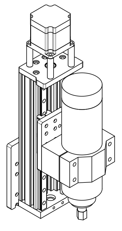
I am modifying the z-axis my Sphinx to improve the working clearance. This design should give me about 165mm of travel and 125mm of clearance from my current waste board location.
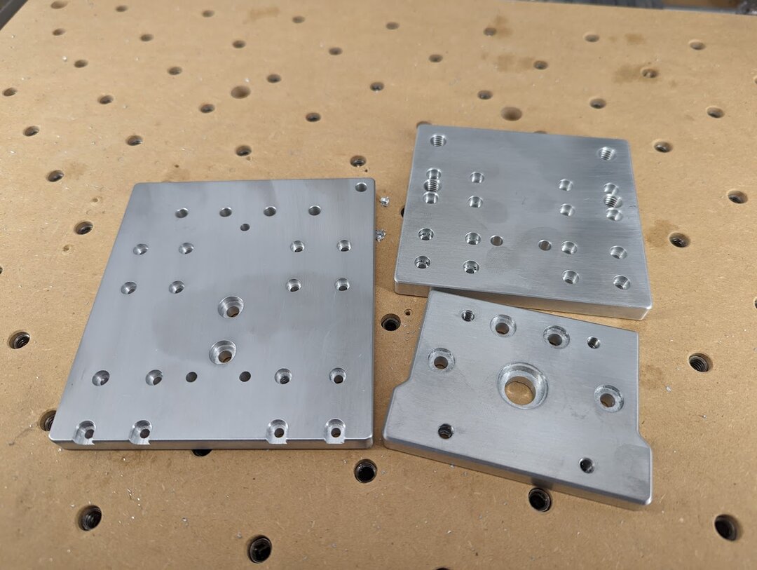
I had some scrap mic 6 cast plate from another build and thought I would use a bit of it for the three plates I had to make. This material is very flat and has a nice ground finish but it does not machine as well as 6061.
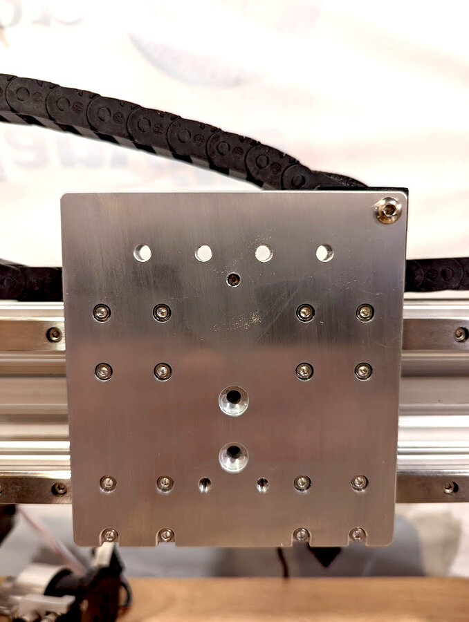
Here is the x-axis as I am test fitting it to the x-axis beam.
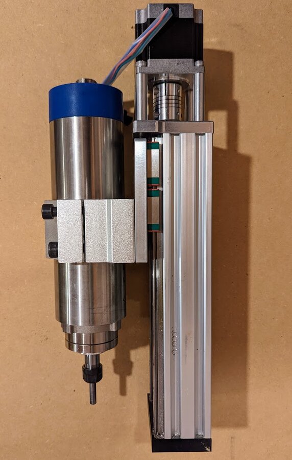
Here is a test fit of the z-axis plate to the z-axis c-beam and spindle clamp.
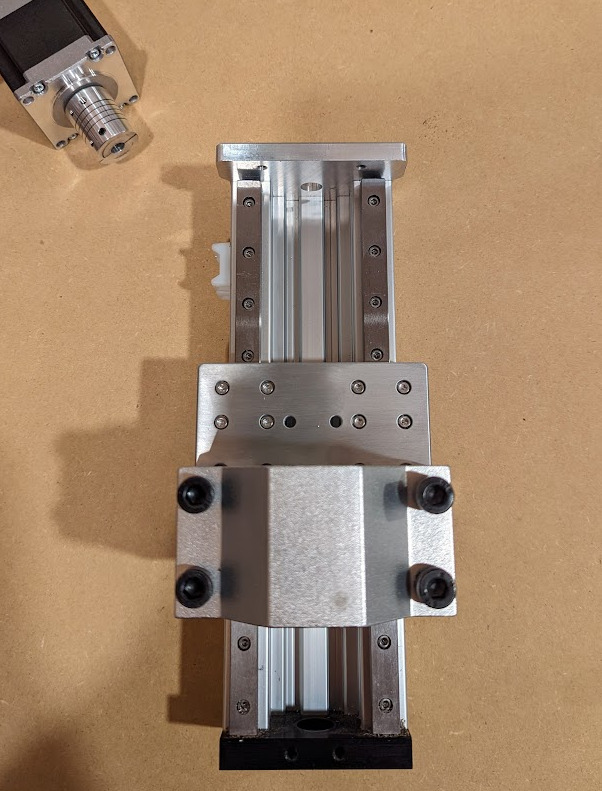
Here's a side view of the z-axis test fit.
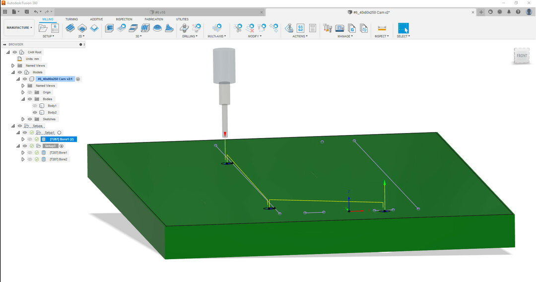
The z-axis c-beam gets thru bolted to the x-axis plate. I decided to mill the holes with my cnc so they would have a nice counterbore. Here is what the process of locating the extrusion on the cnc and milling the holes looked like. First the CAM for milling the 1/4" holes for locating pins in the waste board. Note the origin is located in the front center of where the extrusion will be placed and the holes are on a sketch that aligns with the edges for the extrusion.
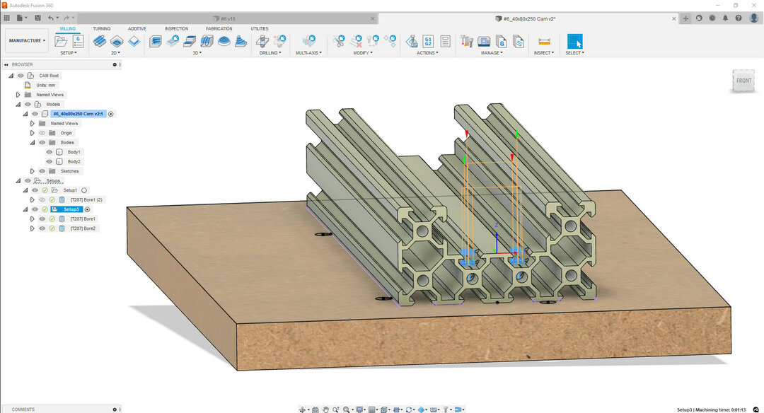
The CAM for counterboring and drilling the extrusion. Note the origin is directly above the origin of the waste board CAM and at the height of the face to be milled.
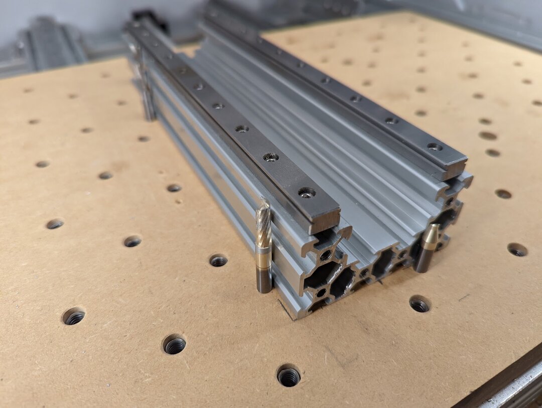
Here is the extrusion on the drilled waste board with "Locating Pins". For this I was able to zero the x,y,z on the waste board surface in a arbitrary spot. Then I reset the z for the second operation on the surface of the extrusion.
Here is a video of the c-beam being milled.
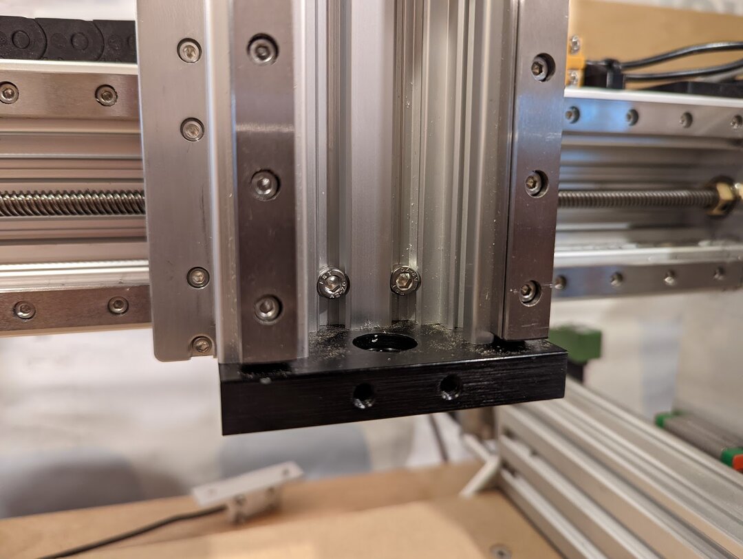
Here is the bolted connection to the backplate. Counterboring this only removed a tiny bit of material and it feels super rigid attached this way.
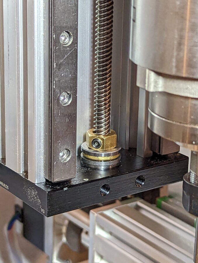
I installed thrust bearings and tension nuts to eliminate and unwanted movement in the lead screw.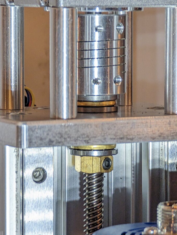
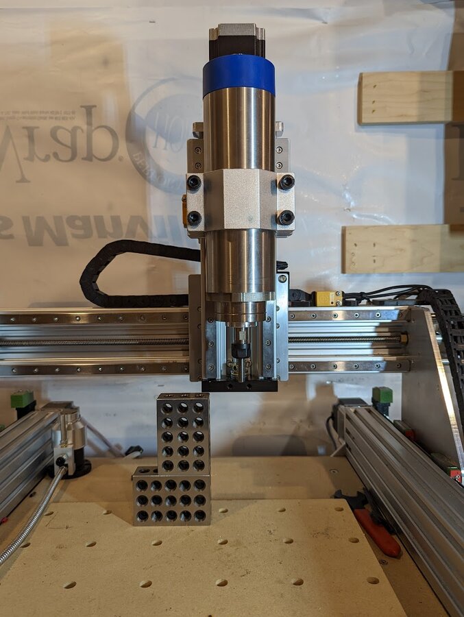
Here is a photo of the finished z-axis mounted on the machine.
Here is a link to a quick video of the z-axis moving
I am happy with the clearance that have now, it will be a lot easer to use a vice or work on thicker projects.

Z-Axis Upgrade For My Sphinx
Build in 'CNC ROUTER BUILDS' published by that-jim, Jul 5, 2023.
Z-Axis Upgrade For My Sphinx
-
-
Build Author that-jim, Find all builds by that-jim
-
- Loading...
-
Build Details
- Build License:
-
- CC - Attribution - CC BY
-
Attached Files: