
My machine is a combination of the following;
Based on Sphinx 55 by Kyo Shinohara link
Inspired by Sorin Iliesu build link
Custom plates from Chris Laidlaw - Blue OX link
For the rails I used the following;
6 - 500mm MGN12 linear rails
2 – 250mm MGN12 linear rails
16 – MGN12H guide blocks
To attach the rails I used;
58 10mm M3 scoket head for mgn12 blocksOpenbuilds has great instructions for the Sphinx 55, so I thought I would just document the things that I did differently to add the MGN12 linear rails.
6 8mm M3 scoket head for x/z-axis plate mgn12 blocks
140 8mm M3 scoket head for mgn12 rail to c-beams
140 M3 t-nut for attaching rails
8 34mm M5 scoket head for anti backlash blocks with spacers
24 20mm M5 button head for plate to end of extrusion ie plate to end of c-beam
8 30mm M5 button head for thicker plate end connection on z axis
16 10mm M5 button head for 6mm plate to t-nut/slot connection
My 500mm rails were just a bit long I had to grind of about 1mm to make them fit between the end-plates on the c-beams.

I used the slide in style t-nuts for the rails, I did not trust the twist in style with so many to fiddle with.

To attach and align the rails I made a small alignment jig that I attached to the c-beams to get the first rail of a pair of aligned to the c-beam. I worked my way front to back snugging the jig down then setting the rails against it and tightening down the rail bolts.

With the first rail aligned to the c-beam, I then checked the rails with an indicator. However using the jig was enough to get the first rails straight, so using the indicator may not be necessary. Once I had the first rail straight and fixed in place I loosely installed the second with the guide blocks and end-plate. That way I could slide the end-plate to align the bearings and then sung everything up.

The front plate on the y axis c-beam will allow the side rail blocks to slide right off the front, for now I installed a few longer screw and nuts for a stop. I know that I will have to work out a better solution than this when I start to run the machine.

I found that I was not happy with the standard locking collars and decided to look for something that fit a little more snugly. I found 5/16 double split shaft collars on ebay and they fit the openbuilds rod very well. Here is a link. I also placed a thrust bearing between the flexible coupling and the c-beam end plate. My theory is that this arrangement will help eliminate unwanted movement.


The stock limit switch locations were not compatible with my linear rail build. After a bit of thought I decided that inductive limit switches would be better with the locations that I had to work with. I cut an aluminum angle bracket for the z limit and mounted it to the z axis c-beam.


The x-axis limit switch is mounted to a 3d printed bracket that attaches to the x-axis c-beam.

The y-axis limit switch is mounted to a 3d printed bracket that attaches to the y-axis motor stand.


I am up and running now so I am calling this build complete. All-though I still have quite a few things I want to do, like build and sound/dust enclosure with a box for all of the wiring and electronics.


Here are a few of the first things I have cut with the machine.
A set of front c-beam plates to prevent the y-axis from traveling to far forward.


A set of 'nuts' to make adjusting the tension on the x-axis motor easier.


And a set of spindle mount brackets to strengthen the spindle mount and make adjusting it easier. Here are links to the files for this BRACKET and CAM FILE


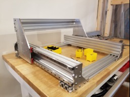
LINEAR RAIL SPHINX 55 (Blue OX plates)
Build in 'Cartesian Style CNC' published by that-jim, Feb 19, 2023.
Machine based on Sphinx 55 built with linear rails.
-
-
Build Author that-jim, Find all builds by that-jim
-
- Loading...
-
Build Details
- Build License:
-
- CC - Attribution - CC BY
Reason for this Build
I wanted a small rigid machine for cutting aluminum.Inspired by
-
Attached Files:


