
Building my "OOZNEST 1000mm x 750mm WORKBEE" cnc
Welcome to this lengthy and hopefully informative thread on how I (with a little help from Openbuilds forum members) went about building this great cnc machine.
Garage Cleared.... and I'm about to embark on my journey down this Desktop CNC path. Join me (a total CNC Greenhorne) as I stumble and muddle my way through this quagmire of mechanical mayhem and sobering software hurdles......
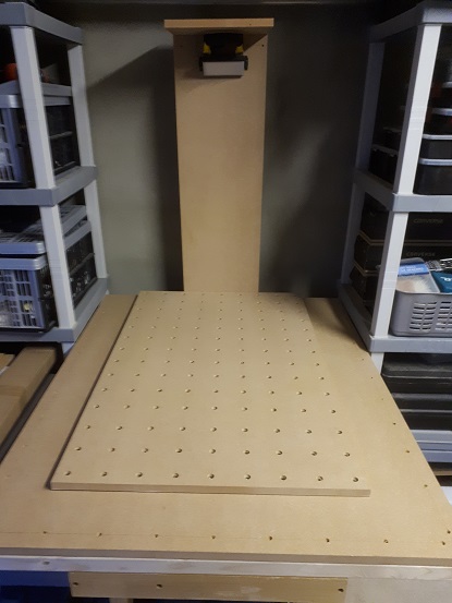
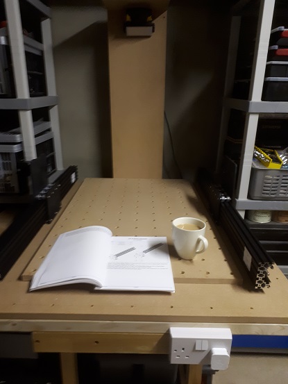
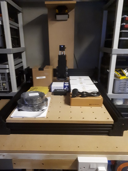
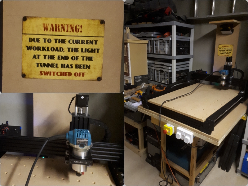
Today (as I wait for my second parcel to arrive due to Parcelforce UK delivering one and not the other, even though they were both collected from source and at the same time) I have made something resembling a "bench" on which to site my Workbee. Not having a huge amount of room to play with, a completely new wooden structure was out of the question so I fashioned a new table top and mounted it on a pre-existing workbench, all leveled and attached with sturdy brackets. I then rigged up a light source and the basis for cable and vacuum pipe management. Attached to the front I've included a double electrical socket for the lighting and the dust extractor, I wish to add an emergency stop button as we progress.
I cant wait to get started building this machine..hopefully it will be a smooth ride. How many of these blinkin wheels are there lol.
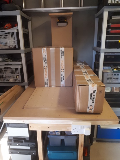
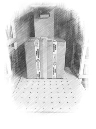
My bench and the Ooznest delivery
UNBOXING - Setting the beast free.
Ok..Lets get to it...
From the outside the boxes seem good and strong, fit for purpose and nicely bound with sturdy bonded tape, followed up with secondary Ooznest branded packaging tape. A nice touch in my book.
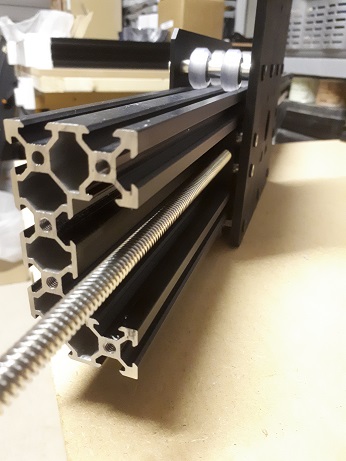
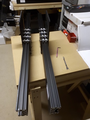
Upon opening the slimmer, elongated parcel first (1200mm x 210mm x 230mm) we have the majority of the rails and screw-threads apart from the smaller Z axis C-Beam and threaded screw (see image below) Each part is easily identifiable via well laid out labeling stickers, for a novice like me this is a treat.
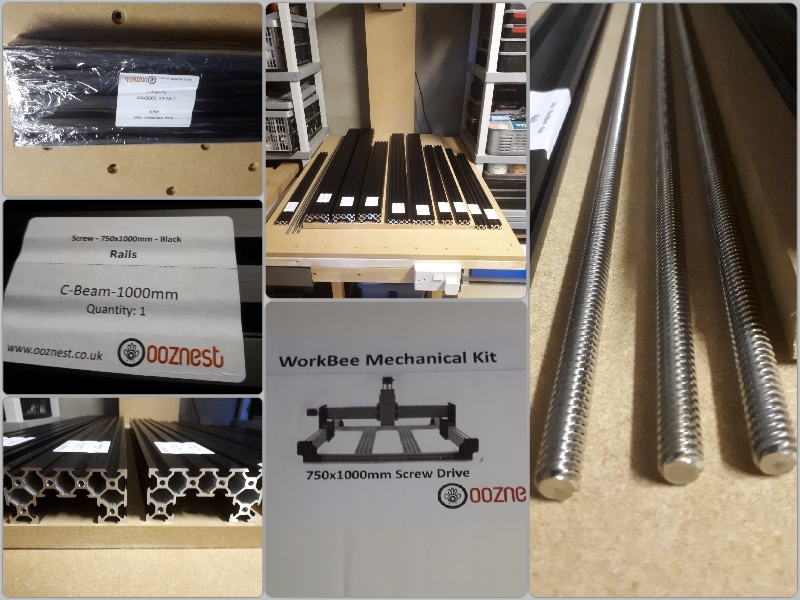
The rails and mechanical build kit
The second, 480mm square box was jammed to the rafters with all the other nuts and bolts to get this baby animated, Wheels, Drag Chains, Electrical and Software, it's all in there awaiting some bright spark with a screwdriver to bring it all to life (well at-least I have a screwdriver)
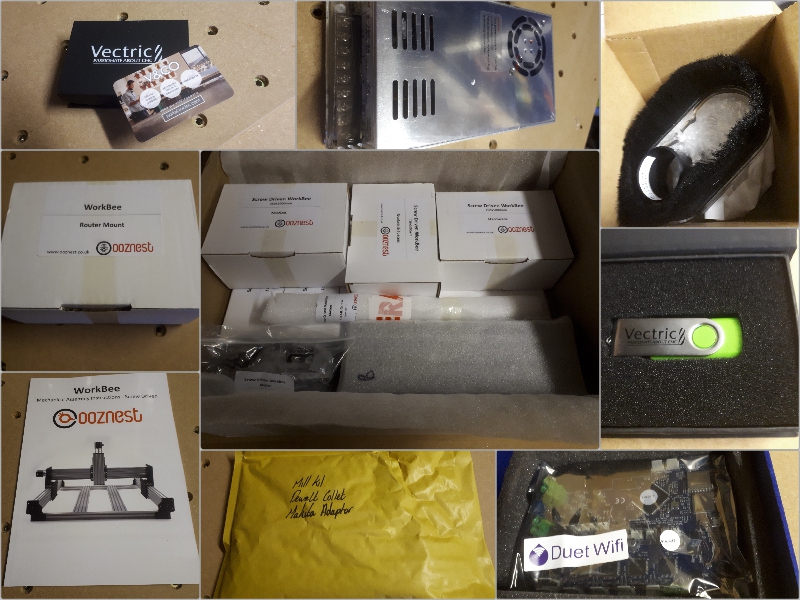
The Nerve Centre in a box
Pt1 - MECHANICAL BUILD PROCESS - Somebody pass the spanner..
Wheels (allow 11/2 - 2hrs) The first task that I needed to perform according to this extremely well presented manual was the wheel construction, all 48 of them....... this was a pretty laborious and time consuming process as each of the wheels and their parts were individually packaged in small Griploc bags. Almost 2 hrs later and with a substantial pile of Griploc bags, we're all done
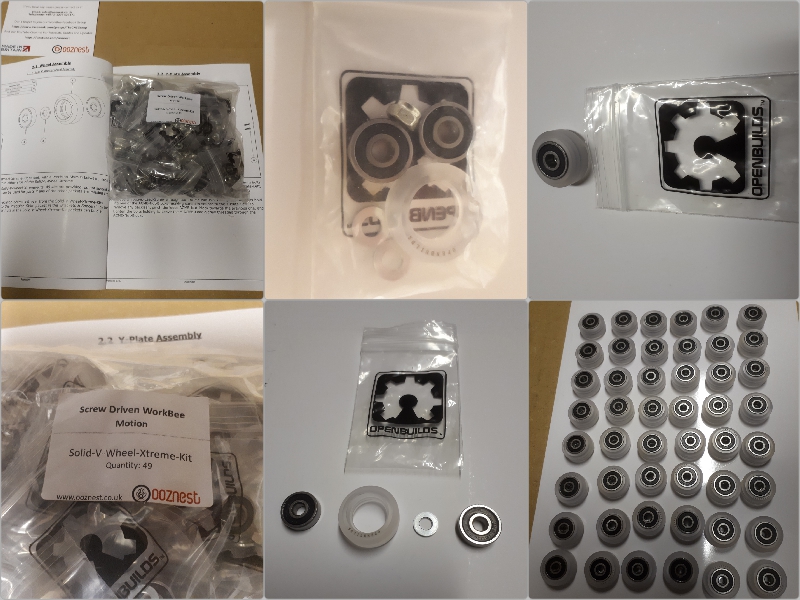
Constructing the wheels
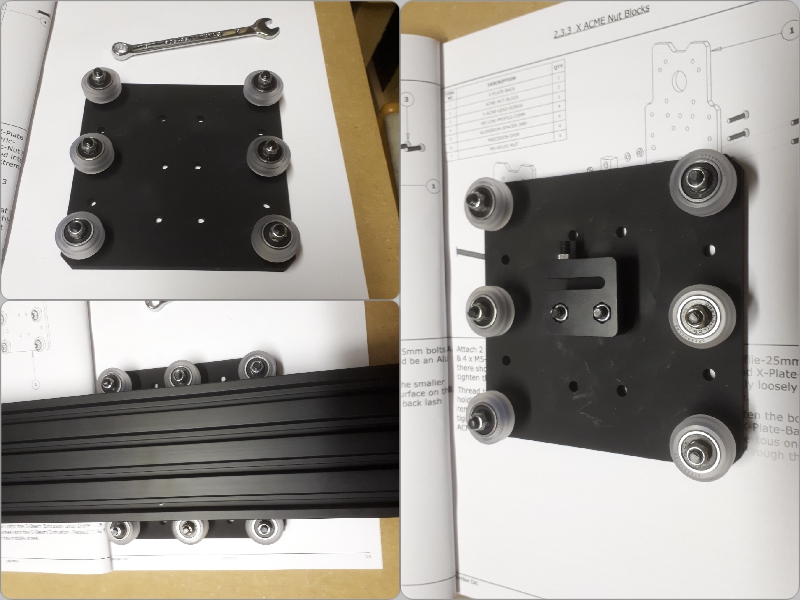
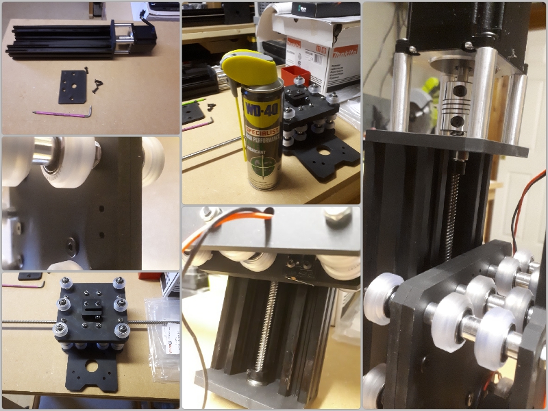
Plate Assembly (allow 11/2 - 2hrs) This evening I thought I'd give the Plate Assemblies my upmost attention, everything went according to plan, with me rigidly adhering to both manual and video for guidance...The only thing I hadn't bargained for... or could ever know...being a newbie to building these machines... was "How Tight is too Tight" I've got all my wheels running on a length of "C-Beam" individually tightening the centric spacers as I went along (all the wheels are touching and rolling) but they seemed a little stiff. Will they be ok, not sure said the demons in my head....Likewise with the Lead Screw passing through the nut blocks (again this seemed fairly stiff to manually turn) should I loosen this off.... again....I'm not sure...At this point I requested help from the forum members (I dont want to get this wrong). Waiting on replies to my plight before progressing onto the next stage...Great satisfaction to see some wheels attached though
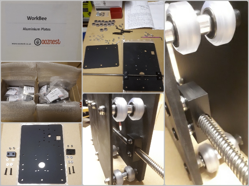
Plate Assembly started, but already we need some help...
This evening finds me attaching one of the NEMA 23 Stepper Motors to the Left "Y" Plate assembly which I completed yesterday. After which I proceeded to make-up the Right "Y" Plate assembly, everything went pretty much according to plan with no hiccups, again the Ooznest Manual coupled with the the Online Videos helped tremendously.
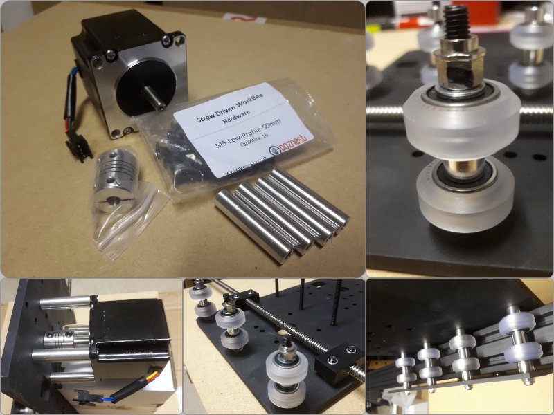
Stepper Motor and Right "Y" Plate Assembly
After a short while I now have two "Y" axis plates running freely on "C" Beam profiles. If I'm honest its been a pretty productive evening, taking my time...Yeah...ROME wasn't built in a day
Left and Right "Y" axis plates
Enough of me standing about admiring what I'd achieved thus far, there is lots more to be done, Quickly moving on to the "X" carriage assembly which again was pretty straightforward, To finish off this evenings proceedings I attached the Anti Backlash Nut to the above plate...So if some kind soul would like to explain the finer points of Backlash (and how it relates to everything) in plain speak then feel free to educate me in my thread.
"X" Carriage Assembly including the Anti Backlash Nut
I've been contemplating whilst still focusing on building this CNC kit, and a thought did enter my mind on the topic of aesthetics.
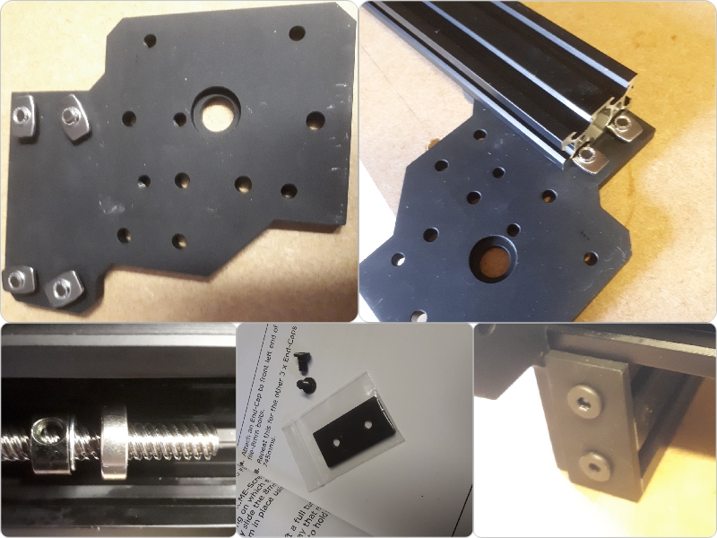
When I purchased my Workbee from Ooznest I opted for the Black coloured Anodised extrusion for all the rails, plates and hardware etc. There are no decals of any sort on the plates as I have seen on the Openbuilds - Stateside version (see image below)
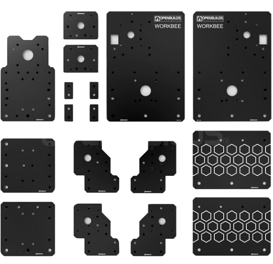
Openbuilds "Workbee" Plates
It's just a small point and I know its not about what the machine looks like that counts more of rather what its capabilities are in the workshop. Perhaps they are not to everyone's taste but I happen to consider this a nice aesthetically pleasing touch especially for the black version and quite possibly would help the novice with quick glance plate orientation, not to mention good advertising for an onlooker. maybe something for Ooznest to consider for the future. Anyway I for one would love a set of snazzy retro fix stickers for mine at some point . So if anyone out there is listening
Working my way through a few more pages of the manual this evening and the last of the "X" Plate assembly before working on the gantry's..I can only describe the going as "slow & fiddly", it could have been a lot easier if my Hex Key set wasn't festooned with colour coded sleeves which negated access to tightening up the front of the "X" Plate to the rear...anyway with a few improvisations I eventually got the job done.
Various stages of the extensive "X" Plate Assembly
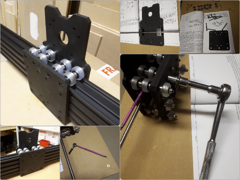
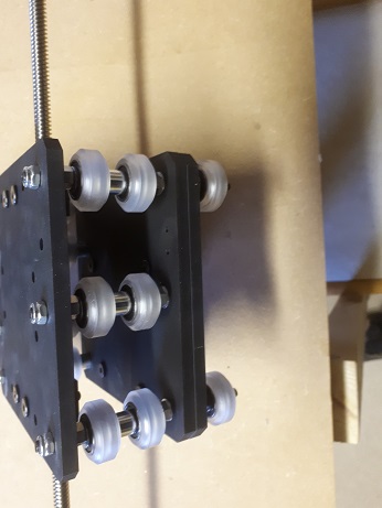
That done, I once again adjusted the eccentric spacers so as all the wheels turned equally along a length of "C" Beam with little force. Next I attached a 250 mm length of "C" Beam to the "X" Plate Assembly and proceeded to screw on the End Mount Motor and the End Mount Bottom Plates to this...I have to confess, at this point, I did make the mistake of putting these on upside down (DOH!)...I should have known really as only one side has recessed holes for the screws to seat in...anyway you live and learn....Once I had these plates correctly orientated I mounted a NEMA 23 Stepper Motor to its designated position at the top of this short profile.
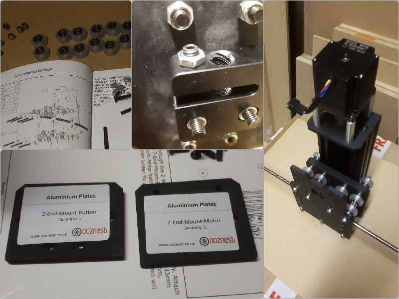
Stepper Motor attached to "Z" Extrusion
Tomorrow I hope to fit the "Z" Acme Screw to its Axis and tidy up the stepper motor assembly, then get cracking on the actual gantry construction. It's looking good thus far..
Well I knew I was going to have a "Bad Day" sooner or later and I never want to see another "Z" Limit Switch in my life again...ever.
This has got to be the bane of Workbee builds the world over, Its a necessary item granted but its so bloody inaccessible if you don't fit it at this particular point in the build...I didn't, and like a great number of builders before me paid the price of having to back track, disassemble a few things and then screw the darn thing into position. not to mention bending a few wires so that an extrusion could safely pass over the top of it....then removing a connector so that I could route the wire properly to the outside of the machine...Not a great day, and it would have been a whole lot worse if @Alex Chambers wasn't about to keep me right.
So for the poor folks that come after me and like me got into a muddle here are some images of how this was all corrected.
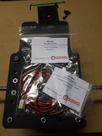
This is where the little switch resides you see the two little holes at the bottom of the assembly (yes right in there)
Here are the parts, (they can give you a headache so please read the manual carefully and dont over tighten those little bolts.
And when you have completed the job you should end up with something like this...
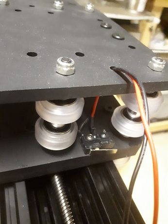
But the problem now will be how to route the wire through the little hole to the outside of the plate opposite when there is a large white connector block attached...Well it's gonna have to come off I'm afraid...again @Alex Chambers advice proved invaluable so I'll use his very quote here...
I felt all of the above needed to be included as to perhaps help others escape the predicament I found myself in this evening,
Apart from this slight glitch in proceedings, everything else went according to plan
Don't forget your PTFE Silicone lubrication for those lead screws
The Weekend starts HERE...
"Where are you going" she said......"Downstairs to the garage" says I......"Sure its only seven in the morning" she exclaims...."Aye, I have a new girl awaiting me, Goodbye my love" I quipped Hahahaha
Probably should have stayed in bed
First things first - Stick the kettle on!
Well that was earlier on, and it's nigh gone 4.30pm and I have just finished up the Mechanical side of this venture..Chuffed to bits I am, but its been a long day and not without a few silly mistakes along the way....How many of you who build these things have done something completely left of centre hahahaha..Half the time was taken up backtracking and squaring up again...Me and the Ooznest Manual fell out and went our separate ways on several occasions I can tell you (but we're all good now) lol
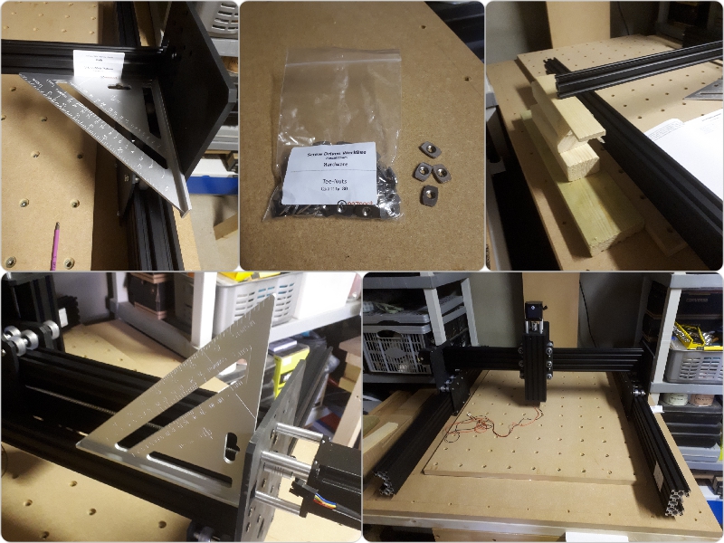
Framing and Squaring up
Today was always going to be about building the framework, joining all the gantries and axis together and getting over the line as far as the Mechanical Build was concerned..First off I worked on the X gantry by adding a length of "V" Slot (750 mm) and the "X" Carriage to the RH side, then joined them to the LH side. adding some corner braces for good measure...."Don'f forget to add the Tee Nuts Guys"
Adding some Corner Braces...Yeah my eyes are getting worse lol
With that job done and dusted I moved onto the Corner Plates and connecting the "Y" Stepper Motors to the Lead Screws...This was a pretty laborious job, (perhaps I needed smaller fingers) lol...I found the Locking collars a little on the tight side...I managed to get them on in the end but it was a struggle at times...The little things are sent to haunt us...
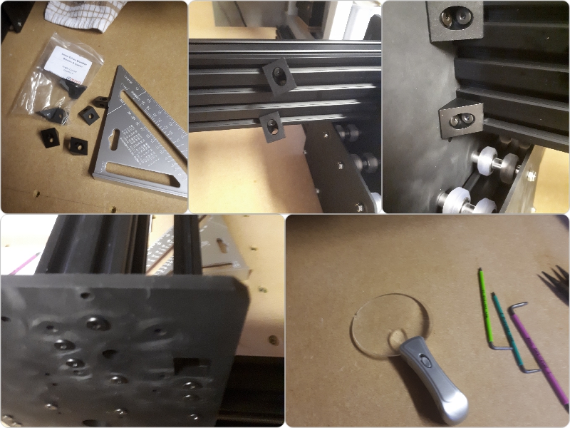
* Point to note instead of threading "T Nuts" along the rails and try to physically line these up to accept a small bolt, It can sometimes be easier if you attach the bolt and the nut the part first (if the situation allows) and slide them onto the rails first before alignment and tightening...
Corners and Covers
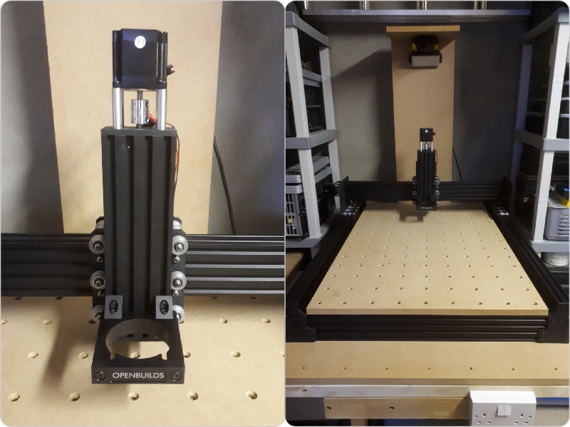
To complete the build I went ahead and added the spindle bracket with the nice Openbuilds script on it....(see images below)
Finally the manual has congratulated me. After many an hour of frustration and downright stupidity on my part I have made it to the end of this exciting chapter of my quest (and I thought this was supposed to be the easy sector)
Well that's it for the Mechanical build, I suppose you wanna see some pics
BOOM! - I'm outta here - It's Tea-Time
Life's a DRAG....
Yes folks...today finds me working on the Drag Chain assemblies, after the obligatory cuppa coffee to get me going on a morning lol
I need to have a bit of a clear-out, so many little Griploc bags and cardboard boxes strewn about the place...I'll keep the boxes though, they're handy for screws etc but the bags need to go lol.
Not many boxes left
As you can see from the above image I have fairly whittled down the parts list, there is not many left to go, but its all techie stuff from here on in...I've built and configured a fair few computers in my time so I wonder how I will cope with this lot.
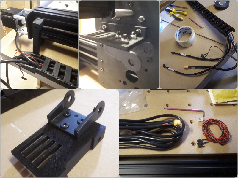
I spent most of the morning making up the mounts and threading wires through the "X" and "Y" axis Drag Chains it was a fairly straightforward affair.
As you can see from the image below I made up the "Y" axis first as per the Online Manual..
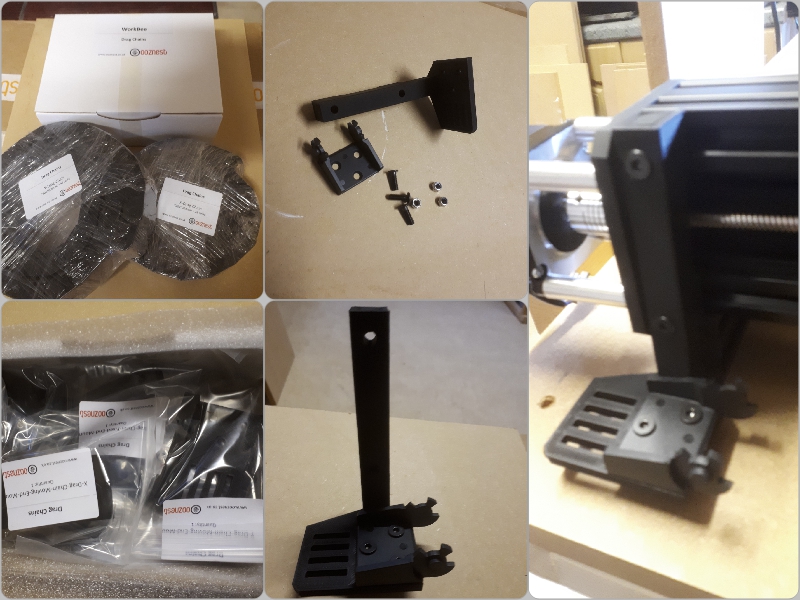
"Y" axis Drag Chain mounts
Ooznest have chosen to move everything online now so I didn't get a hard-copy manual for the Electronics side of things...no biggie ...as here is the link for the Dragchain section.
https://ooznest.co.uk/wp-content/uploads/2018/12/WorkBee-Drag-Chain-Assembly-Duet.pdf
As you can see from the images below (still on the "Y" axis chain) I went ahead and fitted the mounts as instructed...NB* To be honest with you all... it's a pretty hard task to join a Drag Chain to those plastic mounts when the chain is fully loaded with cables and they are attached to the machine, they are rather stiff to couple up and being plastic I was afraid of breaking the lugs off the sides....So I removed both mounts from the machine (noting the orientation) and joined them to the chain first, then I went ahead and attached the whole thing back onto the machine...so much easier than struggling and running the risk of breaking a delicate part. If you find your struggling like me, then give this method a go.
"Y" axis Chain fully loaded
As you can see, a lot of wiring passes through the "Y" axis.... its pretty packed in there..I threaded a steel bar through the centre of the chain, labeled all the wires and their correct rotation (male or female mount end) I then taped the wires together and onto the bar and proceeded to carefully draw everything through the chain whilst pulling the bar from the opposite end....It worked a treat.
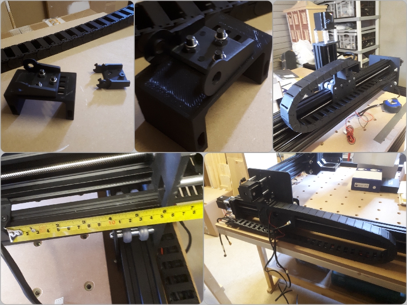
The "X" axis mounts and finished Drive Chain sector.
Now onto the Nitty Gritty......Wish me Luck!
Whilst I had little time to devote to the WORKBEE this evening due to family commitments...(I would have really liked to get the wires all routed) So with what little time I had I decided to put the Power Supply Unit together seeing as its only a small chapter.
Building the PSU
https://ooznest.co.uk/wp-content/uploads/2018/11/WorkBee-Power-Supply-Assembly.pdf
As this part of the build is only a half dozen pages or so in length, I thought...rather than do nothing for the next hour I'll bypass the wire tidying section and concentrate on the PSU
There are not many parts to this and if you've wired a plug you'll accomplish this with ease. There are a few little gripes however....
First job was to attach the XT60 Male connector to the PSU cover via 2 very tiny screws...These screws are inserted through a slot in the cover and into a clamp type affair inside to hold the XT60 plug flush with the front of the unit...Again if I'm being honest this clamp is not going to take a lot of pressure via the screwdriver before IMO it would break...What I did was to push a little scrap of wood under the clamp box so as I could apply a little more pressure to drive the screws home and secure the plug.
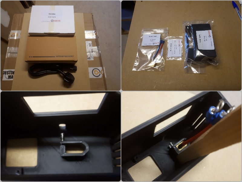
A little piece of scrap wood under the clamping box makes life a whole lot easier and helps prevent breakage whist fastening the screws from above.
Moving along I then wired up the mains supply switch and the LED Volt Meter and secured them into the PSU Cover.
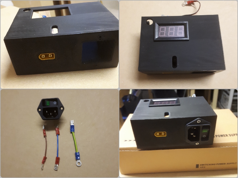
PSU Cover ready to attach to the body
Now for the fiddly bit...it is well documented that you have to get this cover and all its wires pretty darn close to the main connectors on the body in order to wire this baby up and join them both together...Adhering to the wiring diagrams in the online manual I managed to complete the task....this took a while though, so with a few choice words later and checking that my switch (on the side of the unit) was set to my countries correct supply voltage, I was ready to turn on the juice......The unit sprung into life with the cooling fan whirring away the readout initially showed up as 24.5..So I let it settle for a minute or two and then adjusted it down to 24 exactly....
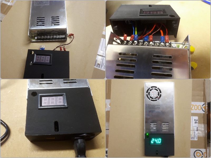
24 is Good
.Job Done!
SNAGS and Remedial work
I experienced only one major snag during the mechanical build process and I guess I may as well catalog it as others may come across something similar.
When I assembled my machine I squared everything up and all was good until I happened to pull on the ends of the Lead Screw at the front...The RH side was nice and taught whereas the LH side seemed a tad loose (Please refer to video footage below)
On conferring with @Alex Chambers and Ryan at Ooznest (many thanks guys) it was decided that I should unfasten totally the LH side end plate...Then undo the lock nut on the screw thread and push the 8mm shim and the bearing a little closer to the end by roughly 1mm, (putting more pre-load on the bearing) then fasten up the lock nut pushed tight to the shim/bearing and re assemble the end plate...it worked like a dream...so if anyone is having problems such as I had, then give this a go....
Pt2 - ELECTRONIC BUILD PROCESS - screwdriver please..
(Duet II WiFi Controller)
This evening I plugged in my Duet controller board into the computer via USB cable. I previously downloaded the drivers and installed those..I have the new Firmware ver. also at hand ready to flash and I also downloaded YAT as per instructions. but my computer wont install the program...Its only an old recommissioned laptop drawn to be used for this job alone 32bit running WIN8.1....so I'll have to get busy on the forums to see if there is a way around this stumbling block.
Talk among yourselves this may take some time
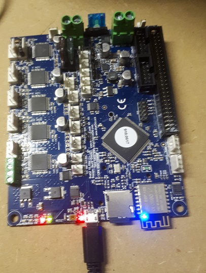
The DUET Control Board
Ok I have resolved the above the issue with my 32bit computer not initializing the YAT program needed to commission the WiFi version of the Duet Controller Board....If your following the Online Manual walkthrough and click on the instructions for this type of setup you'll be asked to install YAT at some point....The link took me directly to a 64bit version, which is no good for my chipset...Undeterred I clicked on the FILES button on the same page and lo and behold I was taken to another page with various options including a 32bit version...I needed to install Ver 2.0 32bit and also the .NET Framework option...This worked and I could carry on my merry way...So for anyone still running a 32bit version of Windows all is not lost.
This evening with my Duet board connected to my laptop via USB, I managed to get it connected to my WiFi network..it did take a bit of time as I systematically went through each process, reading and re-reading the online manual making sure I got this correct. When I got the thumbs up from the software I disconnected the Duet from the computer and proceeded to mount it to the machine gantry....As you can see from the
images I have made all the connection to the board except the Power Cable. I would like also to add a dedicated Emergency Stop button to the system and wire it up whilst I'm in the vicinity...All that's left to do before commissioning the board is to tidy up all the wiring and fit the fans...A nice vented, 3d printed cover for the controller wouldn't go amiss)...
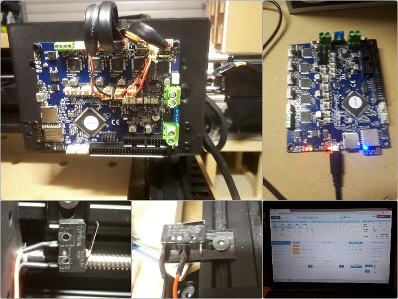
A little cable management needed and we're almost done round here
I made some forward steps today, and from a newbie perspective it's jolly satisfying... Probably not been the quickest build in the world..I made some silly mistakes here and there, which was to be expected I suppose but I've loved every minute of it...
As many will have gathered by now via my cries for help on my thread..I'd been having problems with what I thought was squaring and alignment, I battled for days trying this and trying that, one step forward and 3 steps back...It all turned out to be electrical issues, motor cable wiring to be specific...the only motor that was performing was the X axis, the other 3 needed attention (they sounded like a bag of spanners as they grinded up the tracks). They all needed re crimping and threaded into their connectors before fastening to the Duet Controller once more...to be totally honest I had to do this a few times before I worked out the best way to crimp properly...
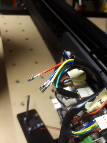
Bad Wiring
It all became a bit disheartening in the end and progress was very slow, maybe I was just unlucky...
But you know what maybe it was meant to be...I had to learn, and what better way than to be in amongst it trying to find a solution...I tightened and un-tightened eccentric spacers in a vain effort to get this sorted. I knew the X axis was smooth and quiet so at least I had something to use as a comparison...
It had to be the wiring, I had eliminated everything else and was at the end of my leash on this, at times I walked away, vowing never to return, but return I did....
So I stripped everything on those wires crimped all the new ends and carefully threaded them back into the connector block before reconnecting to the DUET...One at at time I tested...first the Z axis "BINGO" we were in business....success...the problem with the Y axis just had to be the same....Sure enough this was the case
I'm not overly impressed with this side of the build, I could have done without all that lost time, but again I'm a lot wiser for it...Perhaps Ooznest can address this wire problem is some way especially for newbies such as myself.
One last point was to take care when reattaching the fan assembly they are rather close to the new wires that had just been reinserted into the DUET...IMHO the standoff's could have done with being 10mm or so longer, that little bit of extra room wouldn't go amiss
All sorted now and I'm impressed with the smoothness of the machine...so onto the next hurdle lol providing for all the ancillaries pieces such as dust extraction and cable management...and fastening the machine down. Lots still to do before my first cut....but I'm glad to get past that huge wiring problem.
Noise levels not too bad
Today I bought an Emergency Stop button with a view to wiring this into the system for added security if anything goes awry.
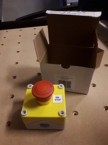
Emergency Stop Button from Screwfix
TOP TIP:-
On the topic of Drag Chains...(for those not in the know)...You don't have to thread wires from one end to another of the chain via pulling rods, string etc etc.... Just OPEN the Drag Chain segments up....all those little flat straps will open up and all you have to do is lay your wires in there and snap them back shut...all that is needed is a small flat headed screwdriver just stick it in the side below the v shape of the flap edge on the outside face and twist... the flap will pop open, when you've laid your wires inside then snap them back shut with your fingers....its easier to do this in increments...Just thought I'd share this little hint
LIFE AFTER THE MANUALS - where do we go from here
Now that I've done all I can do Mechanically and Electronically except for tweaking and adding a few optional extras here and there its time to tidy up, secure the machine to the workbench and fit my Homemade Spoiler Board. https://openbuilds.com/threads/spoilerboard-help.13599/
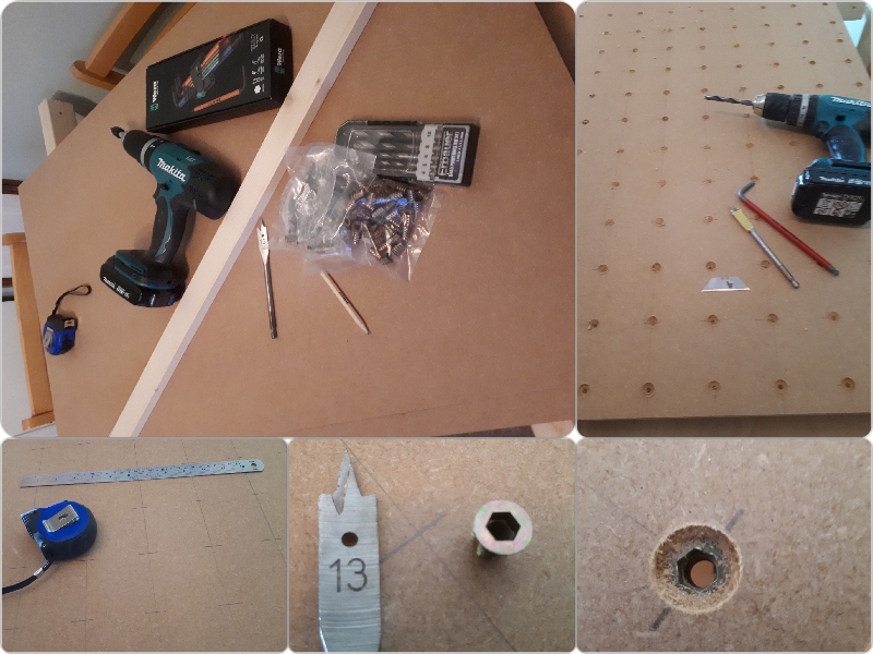
Today I got to fasten everything down to the workbench, I wanted to have the least amount of movement as possible. With some spare materials lying around to help me achieve this. Stud wall battens left over from another job were called into commission as my strengtheners and fastening media, so I set about cutting a sub frame of sorts.
Timber frame cut to specific sizes via plans I keep only in my head
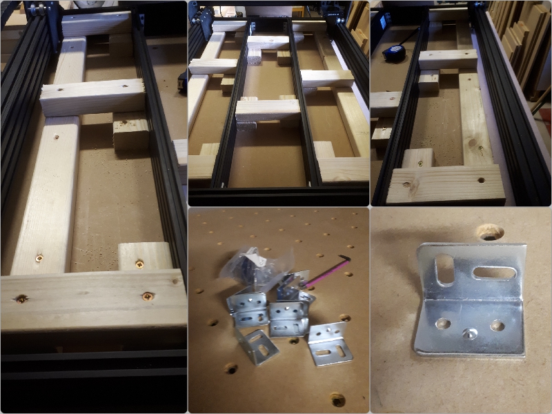
When the timbers were cut and screwed down tight in a kind of grid pattern, it was time to attach some metal brackets to the "V" rails...I bought these from Screwfix very cheaply and they fit the bill..They were just the correct height to attach to the V rail sitting on top of a timber batten.
Fastening bracket plates to the V rails
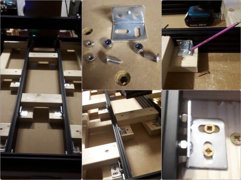
The next stage was to find a way to fasten this altogether...I had a shed load of drop in T Nuts left over from the mechanical build..these were invaluable...I also found a fair few M5 machine screws lying around but they were too long...I needed washers...nah that wasn't going to work....then I found a box of M6 lock nuts into which an M5 machine screw fits perfectly...This gave me enough standoff to use all these spare parts to join both materials together...Finally I screwed the other side of the bracket plate down into the timber...This made for a very very secure fixing...this baby aint going nowhere...
Spoiler board attached
All that was left to do now was to screw down the Spoiler Board through some of the D Nut holes that are outside the main machining area.
This may all seem like a little overkill but there is absolutely no movement in this machine base, which is what I wanted to achieve...
With all this behind me, I decided to try the Makita (with its adaptor) in the "Z" axis.
Then jogged her around a little and she is still running smoothly...a good day was had by all.....
As folks will be aware I have been having a few issues with the Duet and IP addresses...It's still not sorted but I can get a session in so long as I don't power off (or it loses settings) Its probably down to the way this home network is set up so I'm going to get a specialist IT guy to have a look for me. If I have to pay then so be it.
So, for now, Onward we go.
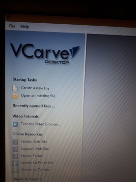
This evening I installed the Vetric software, its only the basic desktop version and has limitations (in workspace dims) as expected, but I'm learning and I plan to upgrade at a later date as all the Vectric software's GUI are basically the same just the higher up the tree you go the more functionality you get. A lot of folks are using Fusion but I felt that it may be too steep at this moment in time.
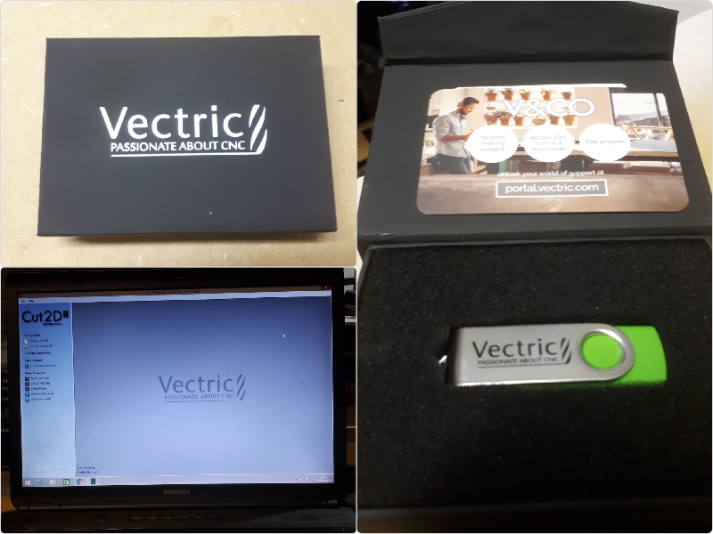
Software installed and registered
We are fast approaching the time for me to cut into the spoiler board., Let us break something
Knowing what I know now I probably wouldn't have purchased the Starter End Mill Set (£100) On hindsight I should have put the money into the PRO version of the software...Think of the number of bits I could have bought for a hundred beer tokens. But Hindsight is a wonderful thing
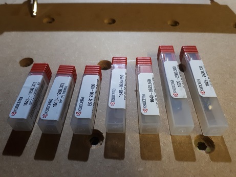
Endmill Starter Set
I have just taken delivery of my new Whiteside Spoilerboard milling bit. It was a little pricey if I'm honest but it was a present so how could I resist.
Within the Vectric software, I have set up a new specialist bit within the database and named it "25.4mm Surfacing Bit" then entered in all its parameters.
I'm hoping against hope to complete this task over the weekend. It should effectively speed things up a little, I only wish my brain would do the same
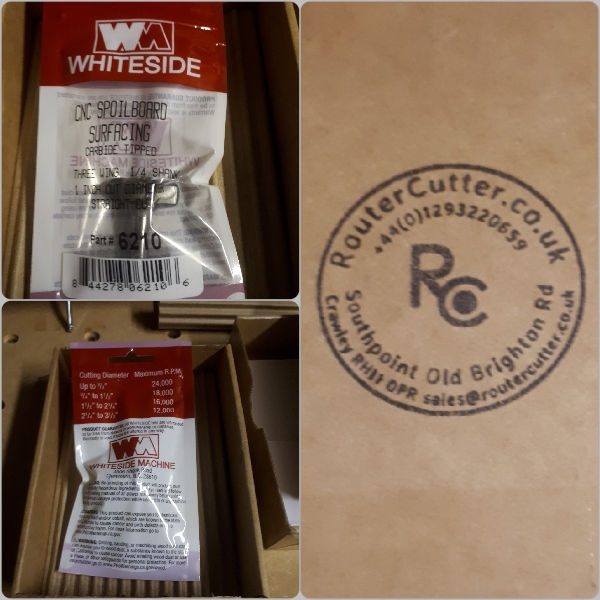
CNC Surfacing Bit
Well, it has been a long trip for me, but today the light shone and we finally got to see the light at the end of the tunnel...I managed to run a couple of pocket passes in the Spoilerboard (it still needs another couple of passes to complete as was expected). The details of the settings I used are in the accompanying thread.
Along the way, I've made some blunders but with excellent forum help, I managed to muddle through and actually get to cut something. The plan tomorrow is to finish the surface board and perhaps make something (that remains to be seen lol), For now, I'm content for the first time in weeks. A glass of red wouldn't go amiss...Cheers!
An overhead view of an 0.5mm pocket pass
A word on PPE - For your own protection
With dust being a factor as in all workshops. You may have a pretty good extraction unit but it's a good idea to arm yourself with a few basic extra protection items such as Safety Glasses, Ear Defenders and a supply of good quality dust masks. Especially when working with the likes of MDF a dust mast is virtually an essential must have. All common sense I know but I just thought I'd give it a mention. These machines coupled with Vac's etc also generate a lot of noise so again provide good protection for your ears. I prefer headset types over the plugs. Eye protection is self-evident with spinning parts fragments of material can leave the machine at a fair rate of knots so do yourself a favour and fit a pair of specs.
Dust is a factor and it gets everywhere unless your machine is encased. Mine is not at the minute, but I may consider a tent type structure in the future. That said, I never liked waste or by-products getting into electronic parts of any machinery I've worked upon, I mentioned this in a discussion with a fellow forum member @Alex Chambers about how the Duet and the PSU were very susceptible to dust ingress. He then unselfishly went away and made me a clip on/off dust cover for the Duet Control Board (see images below)...Although it won't totally eliminate the problem it will serve a whole lot better than the way the Duet is presented at the moment whilst still maintaining constant air flow. He has made this part readily available for those with 3D Printers to download and make your own...Just another reason on how this forum is working for the common good.
Alex's version of a clip on Duet 3D Dust Cover
I'm so glad I invested in the 24mm specialist surfacing bit, it sure has saved a lot of time. Even with this bit each pass still took almost an hour to complete for a work area of 625x540mm. Because my MDF was unlevel it took 4 passes to complete, The upshot now is that I have a level playing field on which to make a few things and learn more about working with wood on the Workbee.
With MDF, dust is a massive problem. I kinda underestimated how much is actually generated as the machine did its stuff. I left my dust-shoe off because I wanted (out of newbie curiosity) to see what was going on, but in hindsight, I should really have put it to use. I'll know next time, the shop vac must be full of very fine MDF particles as I manually followed the cutter around with the nozzle.
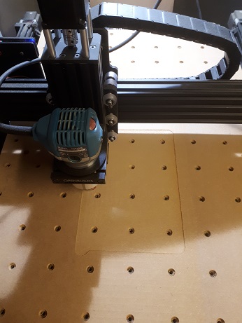
The 25mm CNC Surfacing Bit in action
PRODUCTION - Lets make something/anything
Its taken a while to get to this point whereby I can put this machine to work. It is mainly a hobby but maybe it can become something more, that remains to be seen.
I have learned a great deal along the way with lots of help from others on the forum, HELP that was informative and educational as I struggled as a novice to get to grips with all the small details of the build and using this Workbee CNC. I have to thank them all, unreservedly, for without them I wouldn't be at this juncture.
For the mainstay, I will be using this machine to mill Wood, simple pockets etc.
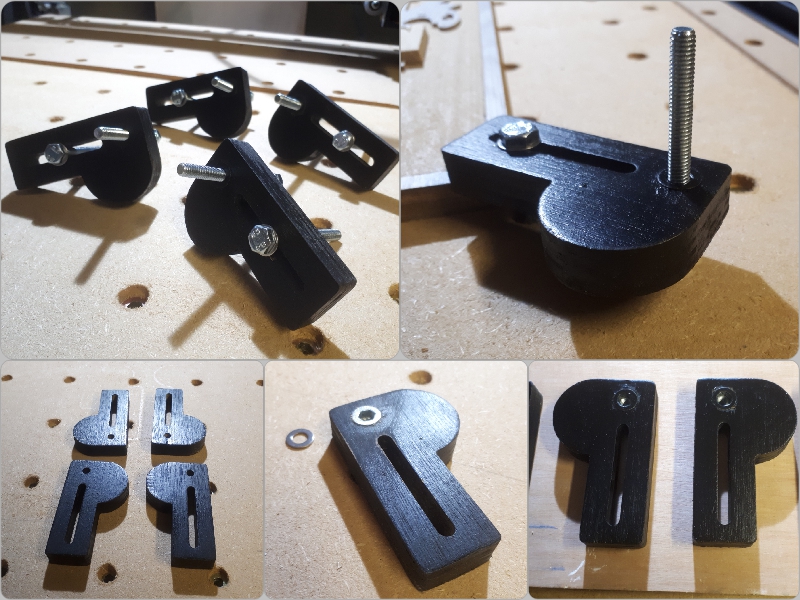
The first Job on the list, I reckoned I'd need a set of simple work-piece clamps. On perusing the "Projects" section of this forum I found a user submitted file for some "P Clamps" these looked (for all intents and purposes) to fit the bill perfectly. So I downloaded the plans and imported them into my CAD/CAM software, set up all the parameters and got down to milling. (Parameter details are in the thread)
The "DUMMY RUN"
One tip afforded me by @Alex Chambers was to always perform a "Dummy Run" of your toolpaths (with the bit clear of the workpiece) just to see that everything is running as it should be before you actually get down to cutting the piece (great advice) it will take a little longer but well worth doing.
AND, this is the result. Lovely clean cut edges with minimal post cleanup.
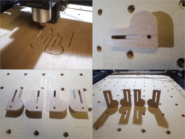
Set of 4 "P Clamps"
The machining took approx 30 mins, give or take depending on the settings. I have still to spray paint them and add the metalwork but all in all, it's been a very satisfying first job for a CNC novice.
I managed to find the time to finish the "P Clamps" today (My first CNC job on the Workbee)
After a light sand and wipe down I spray painted the first coat. added "D Nuts" to the P end for the adjustable/leveling M6 bolts to thread into. I then gave them a second coat of matt black, pushed another threaded bolt through the slot in the opposite direction, this screws down into the "D Nuts already in the spoiler-board.
I can see these being invaluable in the weeks and months ahead
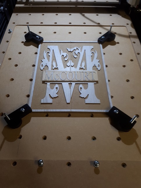
I'm really pleased the way these clamps have turned out - ever so practical
And here they are, fitted and working
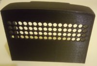
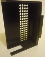
I have to express a massive "Thank You" to fellow forum member Alex Chambers who went out of his way to fabricate me a 3D printed Dust Cover for the Duet Controller board. This duly arrived in the post today and I must say it looks fantastic and very much needed with the amount of dust created especially by MDF. A great addon for anyone experiencing the same. Plenty of ventilation holes for the cooling fans and a side slot for connectability. An all round, aesthetically pleasing professional looking part. It's unobtrusive and fits like a glove onto the Controller board back-plate. I am very pleased with this, and I think he has made the file available to download for anyone with a 3D printer. (Thanks again Alex, appreciated)
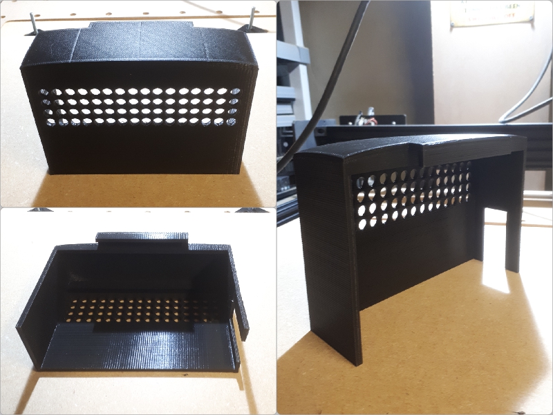
The 3D printed DustCover for the Duet Controller Board, made by Alex Chambers
After making a few little projects with my original Vectric CUT2D software, (as seen in accompanying thread) I found that it was probably inhibiting me slightly so I have decided to upgrade to V-Carve Desktop which should enable a little 3D work.
I would like to include this for folks thinking about purchasing CAD/CAM software. If you are going to follow the "Paying For" route then do a little homework first, I didn't, and opted for a lesser less expensive package and wished I'd gone for the package that really suited my needs going forward. Lesson Learnt....
The BEE and ME
Build in 'Cartesian Style CNC' published by Colin Mccourt, Apr 2, 2019.
I have always wanted to work with CNC machinery...a few years back I got my chance to learn some basics at the Double Glazing Company where I was employed (very basic I might add) before the firm folded and I was made redundant...I wanted to continue learning and when I came across this site which push affordable machines I thought I'd give it a go. So I purchased a !000mmx750mm Screw Driven Workbee from Ooznest and I'm about to embark on my quest as many have done before me...Wish me Luck!
-
-
Build Author Colin Mccourt, Find all builds by Colin Mccourt
-
- Loading...
-
Build Details
- Build License:
-
- CC - Attribution - CC BY
Reason for this Build
Mainly for Signage, And for shapes and parts for various projects that would take ages on the Scrollsaw. -
Attached Files:


