
I have been looking at buying an openbuilds machine to cut aluminum for awhile and waited for the Black Friday sale before purchasing. I went back & forth between the MiniMill, C-Beam & the Sphinx. I liked the MiniMill for being small, but thought I would need a little larger parts than what that could do. Also the MiniMill & C-Beam I did not like the exposed leadscrews on the inside. This sphinx looks like it is the perfect size and appeal to me. I considered going with the larger Sphinx because it was not that much more in price, but decided on this since it fits in my workspace easier. My wife liked the Sphinx name better, so it was easier to sell her on this build. When openbuilds came out with that new Lead 1010 machine I was really tempted to buy that & just replace my MPCNC machine, but it was just a little too big for my 20'x10' shed. My MPCNC fits on a 3'x4' table in the center of the shed. I have already watched the build videos for this machine & did buy the wiring kit to make my life easier.
To get a head start on my build, I have been playing with the electronics enclosure. I really like the simple open design of that case, but for my situation I wanted a little more protection of the electronics, so I started designing a 3d printed plastic case. I started off just making a shield for the top and a thin solid plate where the bottom attaches. I figured the top of that case is the most vulnerable for debris getting in. After a few design changes, I just made a new top & bottom that should work well. After a test fit of the parts in this design, I will upload the files to thingiverse. I use openscad for the design & made the hole offsets & key dimensions easily modified with changing variables.
I also want to make an enclosure for this machine to keep the aluminum cuts from going everywhere, but that will not happen right away. I am planning to use a Bosch Colt for the router as that is what I had for the MPCNC. I would like to get a 400w - 500w spindle at some point, but not sure which one would be a good fit for this machine yet. Anyone have suggestions for which one to get & how it hooks up with the xPRO board?
11/28/2018
FedEx delivered the package today and took me over 2 hours to check the quantities of all the parts against the invoice. I could not believe how they got the exact quantity of all the parts except I had one extra M5 locknut. Tomorrow I plan to start the build. I had ordered a couple of other things with this order, so I had only the parts for Sphinx 55 build on the scale. I was also pleasantly surprised to see the power case kit included. That should make the wiring even easier & more clean.
11/29/2018 3:32am
After a 7 hour print of the case, I discovered there was a layer shift near the bottom of the part. It is only the 2nd time I have printed this part, so 3rd time will be the charm. It is along my y-axis on my Makerfarm i3v, so will adjust the eccentrics on those wheels as that seems to be the culprit & reprint it today. I am weighing the assembly at each step in case I want to know the weights at some point.
11/29/2018
After looking at part of the build video again today, I realized I needed to tap the holes in the 2060 extrusion or use the self tapping screws as the video does. I missed that before. I wanted to tap the holes rather than use the self tapping screws in case I want to connect something else there later. I never tapped holes before, so did some more research before trying this. I cleaned up the aluminum extrusions today & started working on an idea to make a 3d printed cover plate for the 2060's instead.

11/30/2018
After getting up early this morning & trying another idea for a cover, I came up with a design I really like. I do not really need to tap the 2060's, but wanted to do this since I had not done this before. I only tapped the center holes which is all I will need to keep the 1 cover on if the press fit does not hold up over time. I bought a M5 tap from the local ACE store, but my keyless chuck drill slipped on it. I remembered Rick's idea from the Delta-Six thread awhile back & his method of using a 3/16" and that worked quite well.


After drilling it, I used a Stainless Steel M5x40mm screw to thread it. Before taking the extrusion inside, the loose metal needed to come off. So off I went to ACE hardware, but they had sold all 6 pipe cleaners they had yesterday to a lady that was using them for holiday decorations. While thinking of where else I might find them, Dollar Tree came to mind & low & behold they did and they were 12" and only a $1.
Before going home I also stopped at the UPS store to recycle those nice Box stiffening corners that openbuilds put on my well packaged shipment. The guy there really lit up when he saw them & was happy to take them.
For the Tap holder guide, I used V-Slot Tap Holders by makerparts but modified a little & also used his profile as a template for the outer V-Slot connection cover.
I uploaded a couple of STL files of the covers which is an earlier version. The latest version can be found V-Slot Clip-On Endcap Covers by GeoDave which handles all the V-slot sizes. I like to use the Octagram Spiral pattern for top/bottom infill as it looks kind of cool with the right plastic. It is not quite as obvious with this color. BTW, this blue plastic is eSun Light Blue PLA+. Here is a photo of what they look like.


11/30/2018 Evening
I went through Steps 1 & 2 in the build video today. I put regular Tee nuts in for the drop Tee nuts used with the spoiler board brackets. I also added a couple of extra Tee nuts on each side in case I want to mount the P/S or something there. In the last photo you can see that I put a plastic cap on each of those extra Tee Nuts to keep them from rattling. The frame went together pretty good & did not have to redo anything yet. I also have one of those magnetizing devices, so I used it on the ball driver when a couple of the Tee Nuts were hiding behind a bracket. Think he mentions magnetizing it sometime in that video. Here is a link to what I use. Wiha 40010 Magnetizer or Demagnetizer


12/4/2018
I finalized my clip on V-slot cover design and uploaded it to thingiverse V-Slot Clip-On Endcap Covers. This design should work with all the V-slot extrusions. I only tested it with 2020, 2040 & 2060. I went from Step 3 thru step 9 of the build video. Some the bearings did not go in with press fit & had to persuade them with a rubber hammer on wood. The larger wheels needed a bigger hammer, so I sandwiched the wheels between wood before pressing them completely in place with the hammer.


12/7/2018
I swapped both 2060's I had put together a few days ago to the other 2060's I had that were exact same 501mm length. I should have checked these a little more carefully before initially putting it together, but that is just part of the DIY experience. I apparently damaged one of mini-wheel bearings when seating them in place with the rubber hammer as one of them sounds rough and a little tight when spinning it with my hand. I ordered a couple spare wheels, so will not get anymore done on this until they arrive next week. Consequently, I would not recommend using my method of seating those wheels or at least buy a couple of extra in case you mess one up. Not sure how else I could have gotten them seated all the way in. Maybe next time I will just try screwing an M5 screw in with a plate behind it to see if that works better. At any rate, I only messed up 1 in 36 wheels, so that is pretty good. I uploaded a Remix of M5 Tap for all types of V-Slot design today. I printed a simple template with lines for the hole spacing 1/3 of the way down the 2080's for the spoiler board connection.

12/8/2018
While waiting on my other parts to arrive, thought I would design another cosmetic cover plate to cover the 2 front Y-Plates. Only 3 of the M5 holes will be exposed and will need those screws to be 5mm longer, M5x20mm. I initially made the M8 lead screw hole exposed, but thought it might be good to cover that also. Here is a screen capture of what the front & back of that cover looks like.

12/14/2018
Finally got back to this after working on some other projects & being without power for a couple of days. I got the Z-axis done & was playing with making a jig to insert all the screws at once. In the end, the simplest way I found to put them on was adding one screw & t-nut at a time while that line of screws was at the edge of the V-slot. I also changed those 8 M5x10mm screws to M5x12mm screws as those 10mm's did not seem like that grabbed much of the T-nut. It was fun making the jig even though. If I could not have added one screw at a time, the jig would have been better to use. I used a pair of small vice grips on the end of the lead screws to screw them in. They were a little tight to thread by hand. I was not concerned about possibly scarring the end of the lead screw since it would not be threaded on anything. After using on each screw, it did not look like it harmed it any.


12/17/2018
After initially putting the 4-3mm shims on one side of the X-axis C-Beam, I realized I could make a plastic cover for them with the same thickness of the shims & make it look a little cleaner as well as keeping debris out of that exposed end of the C-Beam. The T-nuts with brown shims are there instead of the drop in tee nuts. The brown shims keep them from rattling until that part of the build. I initially tried putting all the 3mm shims into the plastic cover at once & used a index card as a slip sheet, but turned out to be simpler to add one shim at a time, while sliding that cover down into position. The shims stayed on easier that way.


When installing the couplings, I used an X-Acto knife that has an 8mm handle & put that on temporarily to put the coupling on the motor shaft without it going past where the lead screw will go. This worked pretty good. I had remembered from another project that the X-Acto knife had an 8mm handle.

I finished the mechanical part of the build today except for adding the spoiler board. I put the machine on a scale to see the weight of it so far & it is a little less than 29lbs.


12/20/2018
I put together the powercase & designed a couple of brackets to put it on the left side of the machine since it is too big to fit horizontally on the back with the electronics there. It is currently about 24mm away from the Sphinx Y plate. I spent a bit of time making the bracket design in openscad quite customizable to connect to the V-Slot with varying offsets & sizes. You can find the source and STL file expamples: V-Slot Brackets for Meanwell 24v PS With or Without PowerCase You could get it to work with other wider P/S also with some changes to variables. I want to put the spoiler board in before doing anymore with the electronics portion of this build. After I build an enclosure for this, I will probably put the electronics & PS on the outside of the enclosure, but this keeps it all together for now.

12/21/2018
I need a day without rain before getting the spoiler board which I will probably get Lowes to cut it rather than drag my table saw out of the shed to cut it. I measure 19-11/16"x16-1/2" for the size.
1/3/2019
Finished up the wiring today & powered it on for the 1st time with no problems. My limits after homing are X330, Y310 & Z85. I can get another 10mm+ in the Y fairly easy by adding a short 2020x250mm extrusion to back to set back the electronics case. That 2020 drag chain support would hit the case if I let it go further than 310mm the way it is now.
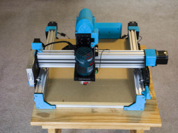
Sphinx 55 with 3D Printed Addons
Build in 'Cartesian Style CNC' published by David Bunch, Feb 3, 2019.
This is a build log of the Openbuilds Sphinx 55 with some 3D printed parts for the electronics and probably other parts as they come up.
-
-
Build Author David Bunch, Find all builds by David Bunch
-
- Loading...
-
Build Details
- Build License:
-
- CC - Attribution - CC BY
Reason for this Build
To cut aluminum plate -
-
Attached Files:


