
OX Tale - the story of my OX build
Garage cleared. OX plates and V-slot received from @plexer and RoboCutters.co.uk. Other parts on order from OpenBuilds Part Store.
Job 1: build a workbench!
Update: 21 April 2015
Workbench complete - I used timber and ply from eBay and an old door that was taking up garage space. The design was from one of Matthias Wandel's excellent woodworking videos on YouTube.

OX parts arrived from OpenBuilds. Then, I finalised the list of mods I'm going to make to the base design - so of course I need to order more parts now
But I have managed to laser cut the dust guards at Fab Lab London.
- Double belts on X and Y axes
- Extra Z axis idler as suggested here by @dddman
- Extra wheels on Z axis
- Acrylic Y axis dust guards based on this design by @Robert Hummel

Update: 23 April 2015
V-slot cut to length (most of it). Not happy with the squareness of the cuts (despite taking time to set up my mitre saw with aluminium cutting blade), so I'll be getting some exercise with the file and abrasive paper!
Holes drilled and tapped in the X beams for the stiffening screws. It's been years since I used a tap, but managed to do all 13 without problems (I hope). Used four brackets to help align the beams during assembly.


Update: 2 May 2015
Over the past week, I got the V-slot squared up and the X beam screwed and Loctited together. Today, I started on the Y plates. Trial assembly with the acrylic guards worked well, and I have now fitted the stepper motors.


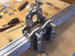
Update: 3 May 2015
I have assembled the Z plate with extra wheels. Needed longer screws for fitting the Acme due to the thicker plate, so hacksawed some 25mm ones down to 20mm. The Z rail runs smoothly and there is a good amount of adjustment in the eccentrics.
Fitting the wheels etc to the X plate has been trickier. First, I needed to ream out the holes for the eccentrics a little to get them bedded down properly and able to rotate. Then, after assembly, I realised that I was suffering from "tight X plate" as described in this thread. The assembly was a VERY snug fit on the X beam. So I opened up the top mounting holes to 6mm and now I have adjustment play in the eccentrics and a much better fit.


Update: 9 December 2015
Well, that was a big gap! Life got in the way and I hit a couple of problems with the build that took a while to sort out. But things are now getting going again.
The main problem was when I added the Z stepper screw rod to the carriage. The OD of the screw rod was too big for the ID of the bearings I had bought. I tried to force one on - big mistake. Solution was to carefully reduce the diameter of the rod using abrasive paper on the areas where the bearings fit, avoiding any damage to the central part that goes into the block. All assembled now and moves smoothly when turned by hand.

I have also tested out the stepper motors and power supply with the controller boards, using an Arduino to generate some test step inputs. All good.
Update: 10 December 2015
A good day today. I installed the Z stepper motor, fitted the carriage on the X beam and attached the Y plates. Earlier in the year, I had tapped the ends of the X beam and back brace, so assembly today was quick.
The back brace is 20x40 in the 3D model of the OX but it is 20x60 in the OX Calculator, so I had ordered 20x60. It fits ok, and means I can run cables inside the V-slot instead of along the top V.


Update: 13 December 2015
I've finished the main assembly. The gantry is rolling smoothly on the side rails. End rails and centre support in place.
I had forgotten to install the extra Z idler - now added.


Update: 14 December 2015
The double Y belts are now in. I was inspired by the build description and 3D-printed end caps of @Prauk and the videos by @Martin.Barfoed. In the end, I didn't use adhesive between the bottom belt and the rail, relying on the end caps to keep everything in place.
Next, I need to work out how to fix the double belts on the X axis. My Y plates don't have mounting for the type of clip that @Martin.Barfoed showed in his video. So I may end up cutting the bottom belt 20mm short at each end, sticking it down centred in the rail, thus leaving a space where there is just a single thickness of top belt which I can fix with T nuts in the standard way.


Update: 27 December 2015
In the end, I decided to fit the X belts using just tension. The metal part from an electric terminal strip was a snug fit on the belts. But I wasn't happy with the look, so decided to order the tensioner blocks made by @Chris Laidlaw. They arrived very quickly and worked well. The only addition I made to them was putting in a piece of acrylic sheet as packing to keep the stacked double belt in place when the clamping piece was tightened down. Photo explains better than words
Then, first movement! I tested the stepper motors and belt drive (slow speed over a short distance) using the drivers and power supply I've bought but with some test code on an Arduino controlling them. It was a big relief to see all four motors in action.
Now, onto the proper cabling and electronics.


Update: 7 January 2016
Happy New Year!
More progress over the holidays. Finally fitted the guards inside the Y plates. Bought some drag chain and fitted the X axis one. And I've worked out how I will fit the Y axis one.
Bit the bullet and worked out in detail how to fit limit switches. Designed some acrylic mounting plates to hold the switches in the correct place. X and Y axes were relatively simple. Z axis was a challenge. I eventually worked out that an acrylic plate fitted inside the rear Z axis plate would position two switches so that the top one is operated by the end plate of the Z screw, while the bottom one will be operated by a "striker" that I will fit to the back of the Z V slot.
I had the mounting plates laser cut and fitted them today. Not wired up yet, and I still need to make and fit the Z axis striker. But I'll cross that bridge tomorrow


PS In fact, I decided to cross it today. I measured up for making a small folded metal bracket and then looked into my junk box to see if I had anything similar that might do the job. I found a plastic cable clip (see photo) and realised that cutting off part of it would give me a curvy part that was about the right size. Quickly fitted it to the V slot and turned the Z axis by hand. Success: the screw head and striker just cleared the acme block, and the curved part of the striker operated the limit switch.
If the screw head and striker had fouled the acme block, plan B was to mount a striker lower on the V slot with a longer arm pointing up at the limit switch. But plan A was good enough!


Update: 13 January 2016
Another week, another milestone! Cabling complete to stepper motors and limit switches. Drag chains installed.
Next step, fit connectors to the cables and start designing the layout of the electrical equipment / electronics that will go in a second hand 19" cabinet that I picked up a while ago.


Update: 31 October 2016
It's been a long time since my last update, but I've made good progress. Electronics and wiring complete. Spindle mount and extractor hood bought and fitted on the Z plate.
Next step: commissioning.


Update: 3 November 2016
I ran g-code successfully today
Over the last couple of days, I downloaded and configured grbl and ran some basic tests using bCNC. Jogging each axis worked, but I found that both the X and Y directions were reversed - quick fix by changing a grbl setting. Limit switches all worked and I'm able to do homing.
My calculations of steps/mm for the steppers, belts, pulleys and acme screw worked out pretty close to correct, although I will need to calibrate. I've increased speed and acceleration from the default grbl settings.
So all that was left to do was create a test piece in FreeCAD and generate some g-code. In my first go, I forgot about setting the feed rate, so (literally) got nowhere fast
But then, this happened ...
Update: 6 November 2016
Next job is to build a bed. After looking at the OX CNC build videos and lots of others on YouTube, I was inspired by CNCJ, Marius and Bjorn (see videos below).
My bed will be 18mm MDF with a grid of M6 threaded inserts on a 75mm grid. On top of this, there will be a 25mm MDF spoilboard with "pass through" holes so that clamps can bolt directly to the bed. The clamps will be CNCed from some maple (I think) - my first proper project
For working on thicker work pieces, I will be able to unbolt the spoilboard and work directly on the bed or on a thinner spoilboard.
I've bought the MDF and am waiting for the hardware to arrive. I tried the bed in place and it makes the OX look even more like a proper router. I didn't want to pay for a large sheet of 25mm MDF only to use a small portion, so I am making the spoilboard from two layers of 12mm MDF (available in smaller sheets). I glued, screwed and clamped it earlier and will see how it looks tomorrow.


)
Update: 18 November 2016
Lots of progress in the last couple of weeks. Bed and spoil board made and installed. Power and dust collection (nearly) sorted out. Laptop running bCNC and making the OX do sensible things. X, Y and X axes calibrated. Just about to make first test cuts prior to levelling the spoil board.
For the bed, I started by cutting the MDF to size and adding two side rails of plywood to match the height of the centre OX rail and provide support. Then I drilled out the grid of clamping holes. Started by using Pythagoras to mark out an X and Y construction line and a parallel X line at the other end of the board. I had made a drilling template from a thin strip of hardwood with holes at 75mm spacing. I drilled small holes and pinned the template in place along the construction lines, then used the template to drill out the intermediate holes. This let me use the template to drill each column of clamping holes.
Next, I drilled out the pilot holes to take the captive nuts with some clearance. Then turned the bed over and got the hammer out! Before fitting the bed, I checked if I could get a clamping bolt into each nut. I'm glad I did this - a few of the nuts had moved sideways in their holes when I hit them. So I had to flip the bed over again and move them. I fixed the bed in place using screws into T nuts in the end rails.
Making the spoil board followed similar steps. Cut to size, mark out construction lines, use the template to drill the grid of clearance holes for the clamping bolts. To fix the spoil board to the bed, I decided to use some of the clamping holes with shorter, recessed bolts. This loses some clamping points but seemed easier than making a separate set of fixing holes in the spoil board and bed.
I had deliberately chosen quite a thick spoil board, to minimise the distance to the spindle for the parts I plan to make. When I fitted it on the bed, I realised there was a bad side effect of this - not enough clearance under the spindle to insert some of my longer shanked cutters into the collet. So I cut a couple of centimetres off the "home" end of the spoil board to give me some clearance.
For power to the spindle, I worked out a position on my garage ceiling to take the shortened cable from the Kress. I just need to finish the wiring from the socket to a fused switch that will be my spindle estop until I integrate it with my main estop. For dust extraction, I have found a hose that will connect to the dust hood. In the short term, I will use my shop vac and dust collector and jury rig the hose to a support from the ceiling. Longer term, I plan a new dust collector with proper hose connection to the hood.
Before calibrating, I remembered that I had never levelled the work bench on which the OX stands. I checked the OX frame in X and Y directions and discovered 1-2mm of twist in both directions thanks to the floor! So, I've put some thin plywood shims under the bench legs and now everything is straight and level.
I've just calibrated all three axes - the grbl settings needed small changes. I think I may have backlash in the Y axis. I'm waiting to get hold of a dial gauge to make some proper measurements. To calibrate the Z axis, I realised I would need that Z plate that I have been meaning to make for a while. I found a piece of aluminium sheet in my spares box and soldered up a cable. I think I can improve on it (it is not as flat as proper gauge plate would be) but it seemed to give repeatable results when I was doing the calibration.
So ... after all that, I need to finish the spindle power cabling and then I can surface my spoil board. I will try a test piece first, to check the programming and experiment with feeds and speeds. Fingers crossed ...


Update: 19 November 2016
First test cuts today: they worked, the OX isn't broken and I haven't hurt myself!
I'm testing how to do spoil board surfacing by cutting small (170mm x 170mm) patches on scrap MDF. I found this website to generate the gcode: G-code generator for Milling a flat surface on the method of "Zigzag" with the main tool movement along the axis Y.
Lessons learned? 1. MDF generates a lot of dust, even when following the cutter with a hand held vacuum nozzle. 2. Always remember to zero ALL the axes after moving the tool into position.
Sorted out the first problem by fitting my dust hood (bought from the excellent Chris Laidlaw, don't think I've posted a photo of it, I will do soon). Great to watch the mini cyclone inside it.
The only thing which is not perfect is the finished surface after the cut. I'm getting tool marks but only at one end of the cut area. I've opened a forum thread about it (Marks when levelling spoilboard) in case anyone can help.
Overall, I'm really happy. I'm getting neat edges on the pockets and (mostly) good surface finish, and the cutter is running cool.
Update: 21 November 2016
More testing on the surface mark problem (see thread link above). Still getting the tool marks on some patterns but much better results switching to a CW spiral. So I was about to get started on surfacing the spoilboard when Glenn recommended I look at tramming to make sure that the spindle is perpendicular to the plane of the X and Y axes of the machine. Hadn't come across this before, so I'm researching how to do it.
I've also measured the backlash in the X and Y axes. This was done with a cheap, no name dial indicator, so I'm going to track down a better one and repeat them. I'm happy with the X axis: backlash of about 0.15mm (0.006"). But the Y axis is worse: 0.30mm (0.012"). The belts feel tight, I'll check the lock nuts on the pulleys, but after that not sure what to try next.
Update: 29 January 2017
Lots of progress over the last couple of months.
With improvements made to the backlash problem (see Marks when levelling spoilboard), I've been researching tramming and have made a tramming arm. 18mm plywood, an 8mm bolt to fit in spindle collet and a slot cut in the end to take the mounting lug of the dial indicator. Just need to get round to using it.
The dust hood works well, but the skirt is a little too stiff for my liking, even having cut slits in it. So I have bought the materials to replace it with one made from 1.5mm neoprene sheet.
Based on the examples I mentioned in my 6 November 2016 update, I've made some bolt-down clamps and stops. Great for getting experience in using the OX and the clamps work well.
Lastly, I have made an alternative thinner spoil board (9mm MDF) for when I have taller items to machine. Cutting the holes and counterbores using the OX was much easier than drillng the original one by hand. The hold-down bolts are M6 furniture fittings with 2.5mm thick head, so they still leave a few mm clearance for surfacing the board and any little accidents! While machining the board, I held it down to the existing spoil board using the masking tape and superglue technique. Worked a treat.
So, I think I will declare the build phase finished, although I'm sure I will constantly tweaking and improving it. This is my last post in this thread; future updates will be "as and when" in the relevant forum. Thanks for watching


OX Tale
Build in 'Cartesian Style CNC' published by Hackscribble, Jan 29, 2017.
1000mm x 750mm OX with some planned enhancements. My first venture into CNC.
-
-
Build Author Hackscribble, Find all builds by Hackscribble
-
- Loading...
-
Build Details
- Build License:
-
- CC - Attribution Share Alike - CC BY SA