Hey, thought I'd post my build log of this really great machine. This is is basically a stock LEAD machine 1010. The instructional videos were used for assembly.
I'm new to the CNC routing process, but I have built and owned a 3d printer some years ago which has helped me take the plunge.
You should be able to click the images to zoom in. Enjoy!
It came packaged well

Getting it unpackaged and laid out


Got the Y axis assembled

Assembled the base frame

Attached the Y rails to the base

Installed the gantry and Z axis

NEMA 32 high torque motors!

Inserting the Y axis leadscrews

All leadscrews in

Put the router on for mock-up

Starting wiring it up


Got the 3/4" MDF spoilerboard cut and installed

Power supply connected, all that's left to do is connect and jog it around!!


I 3d printed this Sharpie holder to start with as I didn't have tools to cut stuff with just yet.


Sharpie attached! I 3d printed the mini gantry plate from openbuilds, downloaded the L brackets from thingiverse, and drew up the rectangular piece that bolts to the router mount. I got the idea from this Openbuilds project: Pen Holder V1.0 and then improvised so I didn't need to use the wheels but rather 90 degree L brackets.
The sharpie just lays in the v groove and two rubber bands hold it on. Big thanks to the maker this thing works great!


This is the only picture I have for some reason but it works great, have done some pretty detailed drawings with it.

Finally got a cut done, this was a 1/4" cheap-o harbour freight bit that was obviously way to big for the piece. Nonetheless, the first cut is done!

Got some T-slots cut in the spoilerboard and cut out come P clamps from Openbuilds (thanks to the author!!)
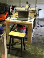
Also built a dedicated table to hold the router. I was really glad to get it off the worktable it was sitting on.

We've done a number of cuts so far, MDF, oak, pine, cedar. It's working great, I need to upload some pics of some of the results.
In terms of clamping the material down, I cut some of these P clamps from " P " Cnc Clamps Big thank you to the maker!
I'm looking to do more of a compression clamp than having a clamp sit on top of the stock and clamp downwards. I'm using these P clamps cut from 3/4" birch plywood. There is a bolt with it's head in the t-slot that I cut in the spoilerboard which I run through the P clamp and tighten down with a nut on top. I made my t-slots in such a way that the bolt I am using can slide into the track and have it's head locked into place so it cannot spin while tightening.
I found the P shape gives decent clamping options. It's not the best but so far I've gotten decent results until I can look into upgrading my setup.
I started working on a dust shoe and tried to print one out, 18h print, came out and checked on it around hour 8 and this is what I got. The hotend is trashed. Could be worse, at least I can upgrade it now!


I keep buttoning up stuff, doing some cable management.

Side view

Got the power supply and controller back here. The Logic Supply IOT power strip has the router plugged into a normally off port. I wired the + up to SPL on my board and the - to ground. Thanks valleskon!

Wires mostly good to go and all labeled.

I had this 4U PC server case laying around and thought it would be perfect for a CNC computer case. Got it up and running and need to build a rack for it underneath the table for it to mount in.

Update 1
I had this button lying around that I was given from a vendor. It was a USB device that you would plug into your PC and when you hit the button, a website opened up or some such nonsense. Anyway, I went ahead and made a stop switch out of it by opening it up and soldering my wires directly to the switch.

Works great for my application!
I got the PC shelf built and it's been living in it's new home for a few weeks now.

Here's some of the stuff I've cut so far, this machine works great, even in my unskilled hands!


Up next:
- Monitor Stand
- Touchplate
OpenBuilds LEAD Machine 1010 40" x 40"
Build in 'Cartesian Style CNC' published by Natesbox, Jan 13, 2019.
Openbuilds LEAD machine 1010 build
-
-
Build Author Natesbox, Find all builds by Natesbox
-
- Loading...


