Welcome to Our Community

Some features disabled for guests. Register Today.

Yet another Sphinx

Discussion in 'CNC Mills/Routers' started by Kevon Ritter, Feb 20, 2017.
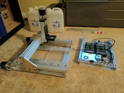
  1. Kevon Ritter

    Kevon Ritter Veteran
    Builder

    Joined:
    Apr 30, 2015
    Messages:
    597
    Likes Received:
    292
    snokid and Paul Stoller like this.
  2. Kevon Ritter

    Kevon Ritter Veteran
    Builder

    Joined:
    Apr 30, 2015
    Messages:
    597
    Likes Received:
    292
    Slow progress as I'm busy with life, but that won't stop me from keeping it clean. It might be a little hard to tell, but my control box is quite a bit smaller than Kyo's. The down side is that the button layout in the other picture actually does not work. There just isn't enough space. I will either have to bring them closer together or create a separate button panel.

    One thing about the aviation plugs is that you can not separate them from your work piece once wired. To circumvent that inconvenience, I have each plug a short length of wire with a 2mm bullet at the end. The wiring is all black, but the heat shrink is color coded.
     

    Attached Files:

    Kyo and Chris Laidlaw like this.
  3. Kevon Ritter

    Kevon Ritter Veteran
    Builder

    Joined:
    Apr 30, 2015
    Messages:
    597
    Likes Received:
    292
    I still have to get power to the drivers. After this, I have to test to see if the Phoenix outputs 5v on the enable pin or if it's at a full 24v.
     

    Attached Files:

  4. Kevon Ritter

    Kevon Ritter Veteran
    Builder

    Joined:
    Apr 30, 2015
    Messages:
    597
    Likes Received:
    292
    It's alive!!!
     

    Attached Files:

  5. Kevon Ritter

    Kevon Ritter Veteran
    Builder

    Joined:
    Apr 30, 2015
    Messages:
    597
    Likes Received:
    292
    I'll hopefully be finished with the rest of the wiring today.
     

    Attached Files:

    Kyo likes this.
  6. Darathy

    Darathy New
    Builder

    Joined:
    Jul 12, 2016
    Messages:
    74
    Likes Received:
    21
    Looks really neat! :)
     
  7. ashish B

    ashish B New
    Builder

    Joined:
    Feb 18, 2017
    Messages:
    58
    Likes Received:
    5
    What spindle are you planning to use ?
     
  8. Kevon Ritter

    Kevon Ritter Veteran
    Builder

    Joined:
    Apr 30, 2015
    Messages:
    597
    Likes Received:
    292
    Thank you!

    Just a Bosch Colt 1hp for now, but would like a 1.5kW as soon as the first few parts get made.
     
  9. ashish B

    ashish B New
    Builder

    Joined:
    Feb 18, 2017
    Messages:
    58
    Likes Received:
    5
    Nice clean setup. Please share the wiring topology once complete. Definitely helpful for 1st timers like me
     
  10. Kevon Ritter

    Kevon Ritter Veteran
    Builder

    Joined:
    Apr 30, 2015
    Messages:
    597
    Likes Received:
    292
    Will do. I'm still in the "hoping everything is correct" phase.
     
    ashish B likes this.
  11. ashish B

    ashish B New
    Builder

    Joined:
    Feb 18, 2017
    Messages:
    58
    Likes Received:
    5
    May I ask what are those connectors called (round with 4 pin) and how motor side cable looks ? Really neat idea
     
  12. Kevon Ritter

    Kevon Ritter Veteran
    Builder

    Joined:
    Apr 30, 2015
    Messages:
    597
    Likes Received:
    292
    I'm using 16mm aviation plugs. You can get them in a few different mounting diameters. I believe the 16mm ranges from 2 to 12 pins. I'll get some better pics for you in my next update.
     
    ashish B likes this.
  13. Giarc

    Giarc OpenBuilds Team
    Staff Member Moderator Builder Resident Builder

    Joined:
    Jan 24, 2015
    Messages:
    2,892
    Likes Received:
    1,609
    They are relatively inexpensive on Amazon.com: aviation connector
     
  14. Kevon Ritter

    Kevon Ritter Veteran
    Builder

    Joined:
    Apr 30, 2015
    Messages:
    597
    Likes Received:
    292
    Everything has power now. Technically, the machine should be able to run, provided everything is hooked up correctly.

    The steppers will only keep about 2" of their original wiring. I won't do any clipping until the chains are mounted.

    The supporting parts for the cable chains are already designed. I just didn't have the time to cut them out. They will be made from 1/4" acrylic.

    I also designed a stand, but more on that when the time comes.
     

    Attached Files:

  15. Kevon Ritter

    Kevon Ritter Veteran
    Builder

    Joined:
    Apr 30, 2015
    Messages:
    597
    Likes Received:
    292
    The cable chain supports are completed which means that I can now start snipping x and z stepper wires.

    I'm still fighting with the computer side. That isn't my strong point. Even though the CBeam guide says 200, 100 steps/mm seems to be the right number based off of short travel tests.
     

    Attached Files:

    Darathy likes this.
  16. Darathy

    Darathy New
    Builder

    Joined:
    Jul 12, 2016
    Messages:
    74
    Likes Received:
    21
    this sphinx will look really nice! Heres a calculator to help you set stepps RepRapCalculator

    just measure how much travel each axis does compared to what you sent and put it in there.
     
  17. Rodm

    Rodm Well-Known
    Builder

    Joined:
    Jan 3, 2017
    Messages:
    121
    Likes Received:
    42
    nice looking build! Can you post a link for the plugs you used for motor wires?
     
  18. Kevon Ritter

    Kevon Ritter Veteran
    Builder

    Joined:
    Apr 30, 2015
    Messages:
    597
    Likes Received:
    292
    Thanks, that will come in handy later.

    This is exactly what I got. But the search terms "aviation plug 4 pin" will give you what you need. I may get a 12 pin depending on how I choose to do my physical interface.
     
  19. Rodm

    Rodm Well-Known
    Builder

    Joined:
    Jan 3, 2017
    Messages:
    121
    Likes Received:
    42
    thanks, I did not recognize them without the metal shrouds pulled up.
     
  20. Kevon Ritter

    Kevon Ritter Veteran
    Builder

    Joined:
    Apr 30, 2015
    Messages:
    597
    Likes Received:
    292
    digital issues... I used to get an error on startup, but now everything seems to be starting normally. My settings are completed unavailable now though.

    Phoenix Controller with DQ542MA Drivers, Windows 10 64bit, GRBL Panel, GRBL 1.1
     

    Attached Files:

  21. Kevon Ritter

    Kevon Ritter Veteran
    Builder

    Joined:
    Apr 30, 2015
    Messages:
    597
    Likes Received:
    292
    After busting my brains on this thing, I've come to the conclusion that my X axis driver is the problem itself. The other three drivers are functioning correctly.

    If anyone is curious to know how I troubleshot the system, here is what I did.
    1) Did a crap ton of wire checking.
    2) I started at the controller. I swapped inputs for different drivers. That told me that the X output does work correctly.
    3) I checked the each enable pin at the controller, the power block, and the screw terminal for the driver.
    4) I then checked the pull and direction for power and they all checked out fine.
    5) The driver is receiving the full 24V like it should. This was check at the driver's screw terminal.
    6) I then checked both stepper coils on the driver screw terminals. This is where it goes wrong. There is no voltage from either coil. When in motion, there should be a voltage as it is an active circuit. I made sure of this by checking with the other drivers. They did create a voltage in each coil.

    That was a lot of time a work wasted... Unfortunately, I did not get them through the parts store. I just sent a message to the seller.
     
  22. GrayUK

    GrayUK Openbuilds Team Elder
    Staff Member Moderator Builder

    Joined:
    May 5, 2014
    Messages:
    1,668
    Likes Received:
    627
    Problem found. :) Lessons learnt. :( Not a complete waste of time. :D
    Gray
     
  23. Kevon Ritter

    Kevon Ritter Veteran
    Builder

    Joined:
    Apr 30, 2015
    Messages:
    597
    Likes Received:
    292
    That is true. Always stay positive!
     
  24. ashish B

    ashish B New
    Builder

    Joined:
    Feb 18, 2017
    Messages:
    58
    Likes Received:
    5
    Kyo. When I ordered the wheel kits somehow I ended up with 6mm spacers (my mistake) but the small vWheels got 1/4" spacers :(
    Would it be a problem ?
     
  25. Kevon Ritter

    Kevon Ritter Veteran
    Builder

    Joined:
    Apr 30, 2015
    Messages:
    597
    Likes Received:
    292
    I'm not Kyo, but the 1/4" should be fine. All they will do is push the plates 0.35mm away from the rails. What matters more are the 9mm spacers as they dictate the distance between the wheel centers. That is important for the gantry.


    And on another note. I've been asked the same questions multiple times. Then I get this response, "For another customer, he connect the PUL - and DIR - 4 PCS Drivers have one driver can't work, but he change the wiring way, all the drivers works." That sounds like utter nonsense to me. The seller has provided absolutely zero information during the repeat messages, but provides a vague solution with no reasoning. Maybe the "other customer" had a wiring issue the first time and didn't catch it.
     
  26. Kyo

    Kyo Veteran
    Staff Member Builder Resident Builder

    Joined:
    Feb 27, 2014
    Messages:
    673
    Likes Received:
    699
    You can use either size of the spacers (6mm or 6.35mm) as long as all the wheels use the same size (exception being the center spacers on the x-axis which need to be 9mm). For example on the Y-axis side plates we use both mini and full size v-wheels. If your mini v-wheels are using the 6.35mm (1/4") spacers the top full size v-wheels need to use 6.35mm spacers as well. The x-axis c-beam rail will change length ever so slightly depending on spacers used to ( +- 0.70mm)
     
  27. ashish B

    ashish B New
    Builder

    Joined:
    Feb 18, 2017
    Messages:
    58
    Likes Received:
    5
    Thanks gentlemen. My mini and main wheel both came with 6mm. reading your reply, looks like I am good to go ?
     
    #27 ashish B, Mar 29, 2017
    Last edited: Mar 29, 2017
  28. Kevon Ritter

    Kevon Ritter Veteran
    Builder

    Joined:
    Apr 30, 2015
    Messages:
    597
    Likes Received:
    292
    As long as everything attached to the same plate is the same, you're fine.
     
    Kyo likes this.
  29. ashish B

    ashish B New
    Builder

    Joined:
    Feb 18, 2017
    Messages:
    58
    Likes Received:
    5
    Thanks. Got it
     
    Kyo likes this.
  30. Kevon Ritter

    Kevon Ritter Veteran
    Builder

    Joined:
    Apr 30, 2015
    Messages:
    597
    Likes Received:
    292
    The new driver arrived today and the machine is running. There are some weird issues on the computer side still though. The next step is to get it squared. A 7/8" (22.225mm) planer leaves maybe a .25mm ridge.
     

    Attached Files:

Share This Page

  1. This site uses cookies to help personalise content, tailor your experience and to keep you logged in if you register.
    By continuing to use this site, you are consenting to our use of cookies.
    Dismiss Notice