Welcome to Our Community

Some features disabled for guests. Register Today.

SOLAC: Space Optimized LAser Cutter

Discussion in 'Laser Cutters' started by Lumberjack Engineering, Feb 18, 2017.
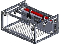
  1. Lumberjack Engineering

    Builder

    Joined:
    Nov 14, 2016
    Messages:
    24
    Likes Received:
    37
    Lumberjack Engineering published a new build:

    Read more about this build...
     
  2. Lumberjack Engineering

    Builder

    Joined:
    Nov 14, 2016
    Messages:
    24
    Likes Received:
    37
    ***Progress Update! (2/21/17)***

    Friday afternoon we cut all of the V-slot to length on the horizontal band saw. Note to future self: OpenBuilds factory cut ends are not cut square with the rest of the piece! I really should have thought to check that before we cut half the pieces - no big deal though, a quick lick on the belt sander and everything was nice and square. Not a knock against the OpenBuilds team at all, just a bad assumption on my part.

    Anyways, this Tuesday (2/21/17) afternoon we went ahead and continued the work on the frame. The attached (slightly out-of-focus!) picture shows Isaac attaching some of the 3D printed brackets. One thing that I also decided that we should do once we finish this thing and upload the files is create some form of a T-nut guide to tell you how many T-nuts go into each extrusion. The amount of times we had to pull a bracket back off to put on more T-nuts is rather embarrassing... ;)
    I think I was actually checking the CAD file to determine where the next set of T-nuts needed to go when this picture was taken. It's just a snippet from a timelapse that I had going on while we were building.

    At this point, we're almost ready to put the motors/belts/pulleys on. I think we're probably shooting for this Friday for the next build time - more updates then!
     

    Attached Files:

    Kyo likes this.
  3. Rick 2.0

    Rick 2.0 OpenBuilds Team
    Staff Member Moderator Builder Resident Builder

    Joined:
    Dec 20, 2013
    Messages:
    2,852
    Likes Received:
    1,524
    Actually that should be a note to all. These cuts are made on the fly as the material streams out of the extruder and a perfectly square cut on a moving object is somewhat improbable. This is why they are all cut slightly long, so they can squared without loss to final length. V-Slot in stick form should always be considered as "raw" material.
     
  4. Lumberjack Engineering

    Builder

    Joined:
    Nov 14, 2016
    Messages:
    24
    Likes Received:
    37
    It definitely makes sense when you think of it in terms of any sort of metal/wood raw stock that you would get, well, anywhere really. Just never crossed my mind. D'oh! As mentioned though, the belt sander squared things up right away. The exact length of each of the extrusions aren't critical, each "group" just needs to be the same.

    @JustinTime : Definitely! Half the reason I started this project page now (rather than when it was finished) is to keep a decent record of what we were doing at each step along the build process. If all goes well, this should help make it easier to write our final design report haha!
     
  5. Lumberjack Engineering

    Builder

    Joined:
    Nov 14, 2016
    Messages:
    24
    Likes Received:
    37
    ***Progress Update! (2/24/17)***

    We worked on finalizing the gantry assemblies and getting some basic linear motion going tonight. I had previously configured GRBL 1.1 on the Arduino UNO back at my apartment, but it took us longer tonight than I'd like to admit to figure out that the reason we were getting weird homing issues was because we didn't have the Z axis endstop or motor plugged in. By default, GRBL homes the Z-axis first, so it kept entering an alarm state when the Z axis homing cycle timed out. Since we didn't have the motor connected, we couldn't tell that it was trying to turn the Z motor. Once we got that sorted out, it seemed like it was behaving mostly correctly. Acceleration seemed very slow (even when set to a high number in the firmware), but we decided to call it a night before we dug into that issue.

    The attached image shows us in the process of connecting the Arduino to the various electronics. Don't worry - cable management is definitely coming soon! :ROFL:
    Not sure when the next time we'll be able to work on the construction will be - this next week should be pretty busy with tests and such before spring break.
    WP_20170224_18_52_56_Pro.jpg
     
    #5 Lumberjack Engineering, Feb 24, 2017
    Last edited: Mar 3, 2017
    Kyo and Sam Staton like this.
  6. Lumberjack Engineering

    Builder

    Joined:
    Nov 14, 2016
    Messages:
    24
    Likes Received:
    37
    ***Progress Update! (2/26/17)***

    I couldn't sleep last night, so I decided to whip up a quick design for a rotary axis for this machine. I know GRBL doesn't actually support a 4th axis, but I think I could just swap it in for the Y axis, and change my steps/mm depending on my part OD. Definitely something that's on the back-burner, but depending on how much time we have, it could happen before the end of the semester!

    Rotary_Axis.PNG
     
    MaryD and Kyo like this.
  7. Sam Staton

    Builder

    Joined:
    Nov 8, 2016
    Messages:
    3
    Likes Received:
    0
    I have been following this for a while and am VERY interested. Do you have an estimate as to when kits will be offered?

    Sam Staton
    Jacksonville, FL
     
  8. Lumberjack Engineering

    Builder

    Joined:
    Nov 14, 2016
    Messages:
    24
    Likes Received:
    37
    Wow, I'm quite flattered! I don't think that I'll be able to offer a full kit for it, but everything is pretty easy to obtain. I do plan to upload a full bill of materials once we're a little closer to completion (to make sure that we haven't missed anything...), and I also plan to include links to where you can get each item.

    If it's the 3D printed parts that you have issues getting, I could probably offer up a kit that included those parts for those that didn't have access to a 3D printer.
     
    Michael Newham likes this.
  9. Sam Staton

    Builder

    Joined:
    Nov 8, 2016
    Messages:
    3
    Likes Received:
    0
    3D printed parts are not an issue - I have a Flashforge Creator Pro. It will be the electronic parts and software issues I will be most concerned with.

    Sam
     
  10. Lumberjack Engineering

    Builder

    Joined:
    Nov 14, 2016
    Messages:
    24
    Likes Received:
    37
    Ahhh - fair enough then. I've started the process of making a pretty detailed parts list, so that should be pretty easy to follow. There's a couple things that I've ran into thus far using the combination of GRBL (for the Arduino motion control firmware) and LaserWeb (for the G-code sender / CAM) that I'll definitely make note of so that others will have a smoother time with it.
     
  11. Lumberjack Engineering

    Builder

    Joined:
    Nov 14, 2016
    Messages:
    24
    Likes Received:
    37
    ***Progress Update! (3/2/17)***

    We spent roughly four and a half hours today working on getting the majority of the Z-axis cutting table in place. We still need to run the nichrome wire (that the parts being cut will rest on) between the two 1" square aluminum pieces, but we're pretty much to the point of putting the belts on for the Z-axis. The table just uses standard 1/2" threaded rod instead of proper leadscrews - this is because the once the piece is positioned at the focal length of the beam, there's no motion with Z-axis. This means that the backlash inherent in this system shouldn't be an issue.

    The below picture was taken in the middle of a rather tedious process - running nylon locknuts roughly 12" down 4 pieces of the 1/2" threaded rod. You can't start them from the bottom - the nylon ring prevents that.
    Pro-tip: Put the locknut in the vise, then use two jam nuts and a socket to move the rod, rather than what we did, which was to put the jam nuts in the vise and spin a pair of vise grips all the way down... Not a fun process - what doofus designed this thing?!? :ROFL:
    WP_20170302_19_26_17_Pro.jpg

    We also managed to mess up the mounting screw countersink depth for the lower threaded rod mount - M5X10s wouldn't grab the T-nuts, M5X15s were too long. Whoops! That was something that we were careful about everywhere else, but these must have escaped our review. We just used one of the Bridgeports to increase the countersink depth to where it should have been, rather than wait on parts to be re-printed. I'll adjust the model to make sure that anyone that uses it in the future will be OK.
    WP_20170302_17_57_21_Pro.jpg

    The rest of the images below show the build in it's current state. Don't worry about the front top threaded rod mounts not being straight - we needed to grab a couple more bushings from Lowe's before we actually mount those. Up next is running the belt for the Z-axis, and then testing it out to see how it performs.

    EDIT: Holy moley I need to clean the lense on my phone! Sorry about the slightly-not-entirely-focused pictures. Also, that second image is messing with my brain - the upper front brackets being loose and slanted makes the entire piece of extrusion look horribly bent! I promise that we haven't driven any cars over the frame. :p

    WP_20170302_20_36_00_Pro.jpg WP_20170302_20_36_15_Pro.jpg WP_20170302_20_36_24_Pro.jpg WP_20170302_20_36_31_Pro.jpg


    Oh yeah! On a side note, I figured out why the acceleration seemed so slow with our X/Y gantries. I (incorrectly!) assumed that the GRBL acceleration/velocity settings were in mm/s & mm/s^2, as they are in Marlin. However, they're in mm/min & mm/min^2. That means that our initial acceleration settings were off by a factor of 3600! Once we corrected that, it started behaving just as expected.
     
  12. David Quayle

    Builder

    Joined:
    Oct 18, 2014
    Messages:
    5
    Likes Received:
    0
    Hi from Australia

    I'm in the middle of building a CNC router and am already planning the next build (too many project and not enough time), which will probably be a laser. I have struggled to find much good info on DIY Laser builds but yours looks promising & I'm following with interest. What laser tube are you going to use, Iv,e been looking at the SPT Laser Technology that can be purchased from china. Why did you settle on 40W, Ive been looking at 80W.

    David
     
  13. Lumberjack Engineering

    Builder

    Joined:
    Nov 14, 2016
    Messages:
    24
    Likes Received:
    37
    Hi there! I'm trying to think of some clever joke about how a laser probably runs backwards down in Australia, but I'm drawing a blank. :ROFL:
    Anyways, I went with a laser tube from ColeTech on ebay (Great deals from CNCOLETECH | eBay Stores)
    They're recommended by the Lasersaur folks (bom · nortd/lasersaur Wiki · GitHub), and I can say that I was quite happy with the tube & powersupply that I got.

    As far as why I chose to go with a 40w tube over 80w, there were a couple of reasons. The first is the size of the tube itself - a 80w tube is 1600mm in length, as compared to a 40w which is only 700. Since I'm currently in an apartment (and while still be once I graduate, at least for the first couple of years), I wanted to keep this thing relatively small. The overall width of the machine is right at 900mm, so an 80w tube would mean a large increase in size of the machine.
    The second reason (and honestly the more important one for me at the moment) is the cost. A 40w tube is half the price of an 80w tube, and is still significantly cheaper than a 50w or 60w tube. Maybe one day I'll do a SOLAC v2 with a more powerful tube.... Guess I better finish this one first though haha!
     
  14. Chris Anderson

    Builder

    Joined:
    Aug 1, 2014
    Messages:
    23
    Likes Received:
    65
    Be aware that there are plenty of 80w tubes that are 1200mm which does fit within the max length openbuilds extrusion 1500mm with more than enough room for mirrors. That being said your are right - 80w is going to cost you a lot more. To me it is worth it though to be able to cut what I want.

    BTW, really like your design concept :)
     
  15. Lumberjack Engineering

    Builder

    Joined:
    Nov 14, 2016
    Messages:
    24
    Likes Received:
    37
    That's a good point, I hadn't even thought about a 1600mm tube being longer than what OpenBuilds offers. Don't get me wrong - if I had the capital available to go for a bigger tube, I definitely would have! It's just those pesky items like making sure that I pay for school/have enough money to move to the location where my job offer is once I graduate/etc that held me back from going bigger than 40w. :ROFL:

    Thanks for all the comments guys! Loving the feedback! :)
     
  16. David Quayle

    Builder

    Joined:
    Oct 18, 2014
    Messages:
    5
    Likes Received:
    0
    It's the "Land Downunder" not "Upsidedown Land":)

    Ive stopped looking at the 80W Tube that I was looking at because I didn't notice that the postage was more than the tube:confused:

    Anyway, the Laser build is still a long way away at the speed I move, I'll just keep watching your progress & driving you crazy with questions.;)
     
  17. Lumberjack Engineering

    Builder

    Joined:
    Nov 14, 2016
    Messages:
    24
    Likes Received:
    37
    Hahaha, Sounds like a plan! Make sure you ask any questions that come up along the way. I hope to make it out to school this week (it's spring break for us) to get the Z axis moving - so keep an eye out for that!
     
    #17 Lumberjack Engineering, Mar 5, 2017
    Last edited: Mar 5, 2017
  18. Lumberjack Engineering

    Builder

    Joined:
    Nov 14, 2016
    Messages:
    24
    Likes Received:
    37
    ***Captains Log. Stardate---Erm, I mean, Progress Update! (3/8/17)***

    Well, doodles. I went out to school today to put the belts on the Z-axis, and quickly realized that the current system just isn't going to work. Hindsight is always 20/20, but I think I really should have seen this one coming. The quick MS-paint doodle below should help explain what the issue is. Essentially, in normal use GT2 belts have contact with roughly 50% of the pulley. I tried to get away with less than 25% pulley contact in the front of the Z-axis... As a result, the belt just skips over the teeth, even when I tension them as much as I can. Bah!

    GT2_Belt_Issues.jpg

    I think that there is at least two decent solutions to this issue. The first would be to go with a belt that has a more aggressive tooth pattern - maybe something like a MXL belt. Going with a belt with a larger tooth profile would mean that it would be much harder to slip on the 3D printed pulleys. However, that would require printing all new pulleys, ordering new belts, and hoping that the Z-axis motor does indeed have enough torque to spin all four leadscrews at once.

    The second solution (and what I'm going with for this project) is to reconfigure how the pulleys are driven. Rather than using one motor to drive all four leadscrews (and thus ending up with the belt skipping over the pulley teeth), we instead pair up the leadscrews and use one motor to drive each pair. This lets us keep the 50% belt/pulley contact that we need. I've attached another MS-paint sketch (telling ya guys, I should have been an artist!) to illustrate what I mean.

    GT2_Belt_Fix.jpg

    The advantage to this approach is that I only have to reprint one pulley and two of the mounts for the cutting table. Hopefully I'll be able to print those and get back out to school this Friday - stay tuned!
     
  19. Sam Staton

    Builder

    Joined:
    Nov 8, 2016
    Messages:
    3
    Likes Received:
    0
    As you said, well doodles. Life is an iterative process. That means we do it over 'till we get it right! Keep on punchin!
     
  20. Lumberjack Engineering

    Builder

    Joined:
    Nov 14, 2016
    Messages:
    24
    Likes Received:
    37
    Thanks for the responses guys! Also, OpenBuilds shared the project on their Facebook & Instagram pages today, so that made me feel pretty awesome! (Which was nice, because I've apparently come down with some form of the plague and feel pretty awful. Blech!)

    @Sam Staton : It sure is! If you're not making mistakes, you're not doing cool stuff, right?!? At least that's what I tell myself...:D

    @JustinTime : Idlers would be great, but unfortunately I don't think they could work in this situation. I wasn't able to find a closed-loop GT2 belt long enough for the Z-axis ( 2.5m+, though I've forgotten the actual measurement at this point haha.), which means that I had to improvise. I posted this picture to Instagram a while back that shows what I came up with (I think I actually found it on a RepRap forum.):
    Instagram post by @lumberjackengineering • Jan 23, 2017 at 7:01pm UTC

    This setup actually does work well - it keeps the correct tooth spacing and runs over the pulleys smoothly. The downside is that I can't (at least I think I can't) run idlers on the backside of the belt, since there's essentially a large lump where the ends meet. There could be something obvious that I'm missing though - it's definitely happened before. :ROFL:
     
  21. David Quayle

    Builder

    Joined:
    Oct 18, 2014
    Messages:
    5
    Likes Received:
    0
    I always worry about things getting out of sync with multiple motors, unless there fancy (and expensive) motors that talk to each other, hence I'm worried about the X axis on my CNC router build getting out for sync, only time will tell.
    I totally agree, if your not making mistakes your not doing anything :)
    I make so many mistakes I must be doing heaps
     
  22. Lumberjack Engineering

    Builder

    Joined:
    Nov 14, 2016
    Messages:
    24
    Likes Received:
    37
    ***Progress Update! (3/17/17)***

    Thanks for the replies guys! Sorry that I've been out of the loop - last week was spring break, but I came down with a strain of the flu, so this week has been rough between recovering from that and just the standard post-springbreak-craziness. Pretty much back to normal now, and I finally have time to sit down and bring you guys up to date.

    Isaac & I tackled the revised Z-axis Tuesday, and found out that that it still wasn't behaving quite right. It ended up being the open-loop belts that we had closed ourselves. Version 3 of the design works however, and once we make some final tweaks I'll show you guys what we settled on.

    We did run into an issue with homing however. While we could manually jog the Z-axis through LaserWeb, if we tried to initiate a homing sequence the entire thing either froze or entered an alarm state loop. It took us about 45 minutes to finally track it down to the fact that the Arduino/GRBL couldn't pulse the stepper motor drivers fast enough to move the axis at the homing speed (which turned out to be faster than the jog speed). With the 1/32 micro stepping, relatively fine pitched rods (compared to a 4 start ACME screw or similar), and the pulley reduction we've got going on, the steps/mm for the Z-axis is roughly 5900. Jog the axis at 5mm/s, no problem. Jog it at 10mm/s and everything goes wonky. This makes sense if we do some math: 5mm/s worth of speed means ((5mm)*5900(steps/mm))/sec = 29,500 pulses/sec. The GRBL homepage says that "It is able to maintain up to 30kHz of stable, jitter free control pulses." So we're right at the limit with a jog speed of 5 mm/s. Not really an issue - that's fast enough for what we're doing here, but it is something that's good to know. Once we got that figured out, all axii home correctly and behave generally as expected. Woohoo!

    In other super exciting news, we also got the laser tube installed & all the mirrors roughly aligned tonight (3/17/17). Tomorrow morning we're headed back out to school to actually run some first test cuts, so that should be awesome. Pictures/Videos/Stories to come tomorrow evening!
     
  23. Lumberjack Engineering

    Builder

    Joined:
    Nov 14, 2016
    Messages:
    24
    Likes Received:
    37
    ***Progress Update! (3/20/17)***

    ...ugh. At this point my partner and I have spent fifteen hours trying to track down the cause of some horrible EMI. The machine will run programs totally fine if the laser isn't powered, but once the laser starts firing it's only a matter of time before the Arduino pulls a hard reset. I'm working with the nice folks over at the LaserWeb community to try to fix this, but I'm totally stumped thus far. I've got a new laser power supply on the way (there goes another $80 over budget :p) to see if that fixes the issue.

    I know that we were bound to have issues at some point in this project, but I *never* saw this one coming. I guess when you're flinging 25kV around that there's bound to be some funny things that happen, but still. We've got a rough draft of the report due this week, so I'm not sure how much more trouble shooting we'll be able to do on the machine itself until this weekend... That being said, I don't know if I'll be able to step away from it that long haha! Hopefully we can get this sorted soon, and start making some cool things!
     
  24. David Quayle

    Builder

    Joined:
    Oct 18, 2014
    Messages:
    5
    Likes Received:
    0
    All I know is sometimes the problems aren't where you think they are, good luck.
     
  25. Lumberjack Engineering

    Builder

    Joined:
    Nov 14, 2016
    Messages:
    24
    Likes Received:
    37
    ***Progress Update! (3/25/17)***

    I'll just leave this here...

     
    David Quayle likes this.
  26. atrueresistance

    Builder

    Joined:
    Jul 12, 2016
    Messages:
    2
    Likes Received:
    0
    Glad to see you got it up and running. Would you be willing to share the STL/bom?

    The latest engraving looks good!
     
  27. Lumberjack Engineering

    Builder

    Joined:
    Nov 14, 2016
    Messages:
    24
    Likes Received:
    37
    Absolutely! A large point of this project is to create a well documented machine for others to recreate, so the BOM & CAD files will all be released at the end. I haven't released any yet since there's been minor tweaks along the way, but once it's finished and I know it's solid I'll update the Build section with all the relevant information.

    @JustinTime : Thanks! Beyond excited to get it working. Time to engrave everything! hahahah.
     
  28. atrueresistance

    Builder

    Joined:
    Jul 12, 2016
    Messages:
    2
    Likes Received:
    0
    I can't wait! What controller are you using? I've got a spare Carbide3d motion controller from a Shapeoko 3 that I was planning to run it with.
     
  29. David Quayle

    Builder

    Joined:
    Oct 18, 2014
    Messages:
    5
    Likes Received:
    0
    Well done,
    Can you tell me what sort of thickness/material you expect it to cut?
    How fine a detail do you expect it to be able to cut?
     
  30. Lumberjack Engineering

    Builder

    Joined:
    Nov 14, 2016
    Messages:
    24
    Likes Received:
    37
    I'm currently using a Arduino UNO running GRBL 1.1f. Not the sexiest controller out there, but it seems to work OK. I would definitely love a Smoothieboard or a Cohesion 3D controller though!

    @David Quayle : With a 40 watt laser, I should be able to max out at about 1/4" thick material. I haven't actually tried any cutting with it yet, so we'll see how it works once I get to that point.

    Anyways...


    ***Progress Update! 4/3/17***
    Nothing spectacular to report here. The past week has been filled with more troubleshooting. The best we can come up with is that the electronics lab we're working in picks up some dirty power when the AC units kick on/people fire up machinery in the shop that it's attached to. I'm honestly surprised that I've got any hair left after seemingly pulling it out the last week, but oh well.

    In slightly more exciting news, we did waterjet out the enclosure panels the other day. Image can be seen over Waterjetting the steel for the laser 1482211338520187963 • Copysta . After cutting the panels out, we washed them, bent the ones that needed to have 90° bends in them (our school's sheet metal bender is garbage...), and then painted them. We decided to go with a silver/grey hammertone color, but it's not quite as consistent as I would like. Oh well, it still looks pretty decent. I'll try to snag a picture of that sometime soon.

    I'm hoping to get the panels put on and everything mounted in it's place sometime this week, and then I'll probably take it to my parent's house to do some testing & see how it performs outside of the lab with potentially dirty power. This next week will be pretty busy (Electronics test Friday, helping host a LEGO robotics competition for area kids on Saturday, and the dry run of our final presentation the following Tuesday), but I'm hoping to make some decent progress on it.

    Oh yeah, before I go, here's a picture of the OpenBuilds logo alongside mine. The OB logo was done at 20mm/s, while my logo was done at 40mm/s. I was absolutely testing out different speeds and their effects on the contrast of the images, and I most definitely did not forget to change the OB logo to 40mm/s as well when I created the G-code via LaserWeb. :ROFL:
    OB_LJE.jpg
     
    Paul Stoller likes this.

Share This Page

  1. This site uses cookies to help personalise content, tailor your experience and to keep you logged in if you register.
    By continuing to use this site, you are consenting to our use of cookies.
    Dismiss Notice