Welcome to Our Community

Some features disabled for guests. Register Today.

Second machine

Discussion in 'CNC Mills/Routers' started by Srđan Marković, Jul 25, 2020.
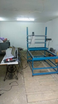
  1. Srđan Marković

    Builder

    Joined:
    Aug 18, 2018
    Messages:
    15
    Likes Received:
    66
    Srđan Marković published a new build:

    Read more about this build...
     
  2. Srđan Marković

    Builder

    Joined:
    Aug 18, 2018
    Messages:
    15
    Likes Received:
    66
    It is almost done but today I found that one bearing is bad.
     
  3. Srđan Marković

    Builder

    Joined:
    Aug 18, 2018
    Messages:
    15
    Likes Received:
    66
    3.jpg
    4.jpg

    Electronics
     
    MaryD likes this.
  4. Srđan Marković

    Builder

    Joined:
    Aug 18, 2018
    Messages:
    15
    Likes Received:
    66
  5. JustinTime

    JustinTime Veteran
    Builder

    Joined:
    Dec 18, 2013
    Messages:
    755
    Likes Received:
    252
    Very sturdy machine! :thumbsup:

    Is it going to be a Plasma cutter?
     
  6. Srđan Marković

    Builder

    Joined:
    Aug 18, 2018
    Messages:
    15
    Likes Received:
    66
    well cnc router maybe I will add plasma
     
  7. JustinTime

    JustinTime Veteran
    Builder

    Joined:
    Dec 18, 2013
    Messages:
    755
    Likes Received:
    252
    I'm curious to see the machine when it's finished. I try to see, in my mind, where the material that you are going to cut will be but I can't with the way the machine looks right now. :(
     
  8. Srđan Marković

    Builder

    Joined:
    Aug 18, 2018
    Messages:
    15
    Likes Received:
    66
    Well you can see my previous build which is 1000x600 mm outer dimension, new one will be same construction but 1500x1000mm and with stronger mechanical and electrical components

    Here is the link
    My build
    and here are some pictures from Solid Works project
    CNC1.JPG
    cnc.JPG

    it is not that color because friend who help me love blue color for AC motors

    I put waste board but I didn't take photos. This is my design. It is changeable gantry height so I can put water table under.

    It is nice because I can unscrew whole machine and put in trunk of mid size car.
     
    #8 Srđan Marković, Jul 27, 2020
    Last edited: Jul 27, 2020
    JustinTime likes this.
  9. Srđan Marković

    Builder

    Joined:
    Aug 18, 2018
    Messages:
    15
    Likes Received:
    66


    Machine was not in level and one of wheels was in the air, but it works without vibrations, that was 7000 mm per minute, maximum is 10000 mm per minute or 2000 rpm exactly as it is written in specification for this steppers. No loosing steps because I connected alarm of drivers when position is not exact, in parallel with x and y limit sensors. I tried this I blocked axis and I instantly got alarm. It was stressful for electronics, steppers, couplers and all mechanic but I had to test it, maximum is about 10Nm measured with my old mechanical torque instrument (stepper rotate on 200 rpm) and in specification sheet it is written 12.5 Nm pretty close, maybe my old torque meter is rusty or now I use 20 mm ball-screw and I made and test torque-meter on first machine with 16 mm ball screw and my friend from mechanical faculty make it work for 16 mm diameter.
    .
     
    #9 Srđan Marković, Jul 28, 2020
    Last edited: Jul 28, 2020
  10. Srđan Marković

    Builder

    Joined:
    Aug 18, 2018
    Messages:
    15
    Likes Received:
    66
    IMG_20200728_194322.jpg IMG_20200728_215946.jpg IMG_20200728_220026.jpg IMG_20200728_220038.jpg IMG_20200728_220055.jpg IMG_20200728_220109.jpg IMG-60ad00b7cea542aa44b54741b1709dd0-V.jpg IMG-c4c631ed9d25967ad25b3b1586089d39-V.jpg IMG-e81fdecb0eb2269a111fa470c081398a-V.jpg


    I made huge mistake I mount z sensor on right side and after that I saw that motor mount disabled it to work. I have to put sensors on left side. This is my son 19y he helped me mounting sensors. He is a footballer and above 180 cm tall (I am 10 cm taller) so you can see machine size. Aluminium plates on z axis are 400x200 mm. I am making one table for for electronic monitor and all this stuff as you can see in the background on photos.
     
    #10 Srđan Marković, Jul 28, 2020
    Last edited: Jul 28, 2020
  11. Srđan Marković

    Builder

    Joined:
    Aug 18, 2018
    Messages:
    15
    Likes Received:
    66
    I hope you understand construction now. I do this way because I do leveling of working table in 0.05mm. Machine levels table by itself, so I push table to zero and then drill holes for 10 mm screws one by one. Z axis push table downward in 4 points with precision it has so when I check metal construction I find 0.1 mm diversity because metal is not perfect. MDF I put has great diversity more than 0.6 mm but I will level MDF with wide tool maybe 1 mm or even 2 mm deep.

    And I have two plates for z axis, as you can see on photos,one is 200x200 mm and other is 200x400 mm. I will explain myself some other time. I want to make machine for different purposes.
     
    #11 Srđan Marković, Jul 28, 2020
    Last edited: Jul 28, 2020
  12. JustinTime

    JustinTime Veteran
    Builder

    Joined:
    Dec 18, 2013
    Messages:
    755
    Likes Received:
    252
    Yes, I understood already yesterday when you posted the other picture of the smaller machine. I just didn't realize that you are going to put the bed on another, higher, level.

    This machine is way more than a hobby machine like most of the machines built and posted here. Good show! :thumbsup::thumbsup:
     
    MaryD likes this.
  13. Srđan Marković

    Builder

    Joined:
    Aug 18, 2018
    Messages:
    15
    Likes Received:
    66
  14. Ronald Lyons

    Builder

    Joined:
    Aug 26, 2021
    Messages:
    1
    Likes Received:
    0
    This is a very nice design, I like that it's made out of square tubing which is very strong and solid, straight... and easy to weld together square. I like how you were able to save money too with the ball screw in the center of the X axis, and how you were able to mount the rails directly on top of the tubing on the X axis...

    The only question I have is, why did you decide to make the Z so tall? I would maybe like to do something similar to this but I think I would only need 4 or 5 inches of Z travel, yours looks as if it may have a full foot of Z travel!

    Very nice design, probably my favorite on the site. By moving the gantry UNDER the table you really solved a lot of problems.
     

Share This Page

  1. This site uses cookies to help personalise content, tailor your experience and to keep you logged in if you register.
    By continuing to use this site, you are consenting to our use of cookies.
    Dismiss Notice