Welcome to Our Community

Some features disabled for guests. Register Today.

Sea-OX

Discussion in 'CNC Mills/Routers' started by Steven Bloom, May 29, 2015.
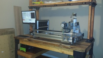
  1. Steven Bloom

    Steven Bloom Journeyman
    Builder

    Joined:
    Dec 18, 2014
    Messages:
    194
    Likes Received:
    104
  2. Mark Carew

    Mark Carew OpenBuilds Team
    Staff Member Moderator Builder Resident Builder

    Joined:
    Jun 28, 2013
    Messages:
    2,742
    Likes Received:
    2,407
  3. Steven Bloom

    Steven Bloom Journeyman
    Builder

    Joined:
    Dec 18, 2014
    Messages:
    194
    Likes Received:
    104
    Well tonight I designed and printed a prototype of my first part. The part is a "Y End Plate". You will need 4 of these for the printer. I will post the .STL file for now. I used Solidworks for the first time, its not too bad.
     

    Attached Files:

  4. Steven Bloom

    Steven Bloom Journeyman
    Builder

    Joined:
    Dec 18, 2014
    Messages:
    194
    Likes Received:
    104
    Okay, I have now proven that my Endplate will now work. I have printed out a bunch of pieces with my 3D printer and have assembled them. I now that I will also need two double corner brackets , one three hole plate and one corner connector bracket. Let me know if everyone things this will be sturdy enough for the corners.


    2015-05-30 16.26.55.jpg 2015-05-31 14.37.12.jpg 2015-05-31 14.37.28.jpg 2015-05-31 14.38.51.jpg 2015-05-31 14.39.13.jpg 2015-05-31 14.40.21.jpg
     
  5. Joe Santarsiero

    Joe Santarsiero OB addict
    Staff Member Moderator Builder

    Joined:
    Oct 30, 2014
    Messages:
    902
    Likes Received:
    196
    That's crazy. I love it. Being a designer and having to color code everthing to help convey intent, I love the fact you printed everything in different colors. Great model Steve. I think you should build and work out any further kinks now.
     
    Steven Bloom likes this.
  6. Steven Bloom

    Steven Bloom Journeyman
    Builder

    Joined:
    Dec 18, 2014
    Messages:
    194
    Likes Received:
    104
    Here is my new faceplate design for the Sea-OX. I am going clean it up a little. But you can see where I am going. By the way, A Sea-Ox is another name for a male Manatee. They are very tough and can push through anything !!

    faceplate.png
     

    Attached Files:

  7. Ronald van Arkel

    Staff Member Builder Resident Builder

    Joined:
    May 7, 2014
    Messages:
    472
    Likes Received:
    245
    There are easier ways to see if things fit with CAD programs, it's crazy indeed to print all but darn it looks cool! :thumbsup::ROFL:
     
    Steven Bloom likes this.
  8. Steven Bloom

    Steven Bloom Journeyman
    Builder

    Joined:
    Dec 18, 2014
    Messages:
    194
    Likes Received:
    104
    What program would you recommend ??

    Thanks Steven
     
  9. Ronald van Arkel

    Staff Member Builder Resident Builder

    Joined:
    May 7, 2014
    Messages:
    472
    Likes Received:
    245
    Just SketchUp Make 2015.

    I've been using different 3D programs over the last 22 years and I like SketchUp the best. Been using it since January this year. The only downside I´ve found is that you need to make some objects at a scale of 10:1 else SketchUp will crap out on you: for example making a Acme rod, you must draw it as 80mm as 8mm will give you errors with extrusions and the follow me tool. Some plugins might be needed to complement your SketchUp install, like drawhelix14, ene_uprightExtruder_v1.2.1 and a few more. DXF/DWG import and Boolean function are only part of the Pro version, that's the downside of the free SketchUp. I don't use the render functions as I only care for functional design. Lining up parts might be the biggest task you will face.

    For 2D I still use an older AutoCAD version ;).

    -Ronald
     
  10. Steven Bloom

    Steven Bloom Journeyman
    Builder

    Joined:
    Dec 18, 2014
    Messages:
    194
    Likes Received:
    104
    So tonight was a good night and I did some more design work. Here is a completed "Sea-Ox" 3D Printed plate. I will getting two of these in stainless steel. My Nema-23 motors also came in. They are capable of 24KG/CM. They should be good and strong. I also designed this part to act as a corner brace. Maybe I can get someone to sell them at their site.

    2015-06-02 23.08.51.jpg 2015-06-02 23.09.18.jpg 2015-06-02 23.22.16.jpg
     
    Joe Santarsiero and Mark Carew like this.
  11. sw3Dp

    sw3Dp New
    Builder

    Joined:
    Apr 26, 2015
    Messages:
    29
    Likes Received:
    8
    Manatee I love it, looking foreword to seeing it swim.
     
  12. Steven Bloom

    Steven Bloom Journeyman
    Builder

    Joined:
    Dec 18, 2014
    Messages:
    194
    Likes Received:
    104
    Well I had some time again to design the "Y Inside Plate". I don't know if I have everything on the plate but I will revisit it again tomorrow night. This plate should allow a "X" C-beam to mount to it and have the normal C-Beam End posts tie into it.

    Enclosed is a picture and the STL file as of now.

    yyy2.png
     

    Attached Files:

    • yyy2.STL
      File size:
      186.8 KB
      Views:
      190
    silopolis likes this.
  13. Steven Bloom

    Steven Bloom Journeyman
    Builder

    Joined:
    Dec 18, 2014
    Messages:
    194
    Likes Received:
    104
    Here is the "Y Outside Plate". I also added a picture of how the two pices would kind of line up as well. Also, the STL file is included.

    yyyb2.JPG yyyfull.png
     

    Attached Files:

  14. dddman

    dddman Journeyman
    Builder

    Joined:
    Mar 2, 2014
    Messages:
    468
    Likes Received:
    187
    I suggest that you may extend it to be near your X beam to prevent stuff to get on your wheel or add holes to be able to add a brush (hard to find)
     
  15. Steven Bloom

    Steven Bloom Journeyman
    Builder

    Joined:
    Dec 18, 2014
    Messages:
    194
    Likes Received:
    104
    Not sure what you saying by extent it near X Beam. Enclosed is a new picture. I was hoping that with this design there would be a minimum amount of dust near the wheels.

    yyyfull2.png
     
  16. dddman

    dddman Journeyman
    Builder

    Joined:
    Mar 2, 2014
    Messages:
    468
    Likes Received:
    187
    OK I understand now :) I taught that the bog plates would have been on the outside like the OX
     
  17. Steven Bloom

    Steven Bloom Journeyman
    Builder

    Joined:
    Dec 18, 2014
    Messages:
    194
    Likes Received:
    104
    I am now getting closer. Tonight I will start on the plates that will travel across the X axis and hold the Z. This part will be tough for me.

    yyyfull3.png
     
    JacquesBotha likes this.
  18. Ronald van Arkel

    Staff Member Builder Resident Builder

    Joined:
    May 7, 2014
    Messages:
    472
    Likes Received:
    245
    The 20*40mm V-Slot at the back, move it as far to the edge of the back of the side plates, put the 90º corners to the front of it; this helps a bit with sturdiness. Another tip: use 2 Acme blocks on each axis, put them apart as far as possible and put them in a distance of steps of 8 mm, hart to hart. This will reduce vibration and slack. Looking good!

    -Ronald
     
    silopolis likes this.
  19. Steven Bloom

    Steven Bloom Journeyman
    Builder

    Joined:
    Dec 18, 2014
    Messages:
    194
    Likes Received:
    104
    More Changes . Moved the V-Slot back and now can use two acme blocks per side.

    yyyfull4.png
     
  20. Steven Bloom

    Steven Bloom Journeyman
    Builder

    Joined:
    Dec 18, 2014
    Messages:
    194
    Likes Received:
    104
    I am done with work for the night but I got a chance to work on the X/Z Plates. It is starting to come together.

    yyyfull5.png
     

    Attached Files:

  21. dddman

    dddman Journeyman
    Builder

    Joined:
    Mar 2, 2014
    Messages:
    468
    Likes Received:
    187
    You'll gain some X travel if you put the big Y plates on the outside of the C-Beams, but as I said earlier, you'll have to modify a little bit your inside plates to protect your wheels/belt.
     
  22. Steven Bloom

    Steven Bloom Journeyman
    Builder

    Joined:
    Dec 18, 2014
    Messages:
    194
    Likes Received:
    104
    Actually the X is 500mm. It will still travel the same distance either way. The only way to make the trave longer is to decrease the size of the gantry that is holding the spindle or increase the X beam
     
  23. dddman

    dddman Journeyman
    Builder

    Joined:
    Mar 2, 2014
    Messages:
    468
    Likes Received:
    187
    True, you'll just optimize the footprint the other way.
     
  24. Steven Bloom

    Steven Bloom Journeyman
    Builder

    Joined:
    Dec 18, 2014
    Messages:
    194
    Likes Received:
    104
    Almost done designing the last part of the Z Axis. But I have a question ??? What is the normal amount of room betwwn the top of a wood board and the cutter. I think I can cut something up to 40mm thick.

    Is that enough room ?? I have no idea what the standard is .

    Thanks Steven

    yyyfull6.png
     
  25. Joe Santarsiero

    Joe Santarsiero OB addict
    Staff Member Moderator Builder

    Joined:
    Oct 30, 2014
    Messages:
    902
    Likes Received:
    196
    I think that depends on what you cut and what precision you expect. closer to the gantry means better precision. The further out you hang that thing in a cut the more torque that's translated to the gantry and the more doc plays a part. The other problem to consider is that bits and drills come in different lengths. So, you have to factor that in as well. 40mm is good, but do you need that much of a gap? on that note, You can throw in more or less spoil board for adjustment.
     
    #25 Joe Santarsiero, Jun 6, 2015
    Last edited: Jun 6, 2015
  26. Steven Bloom

    Steven Bloom Journeyman
    Builder

    Joined:
    Dec 18, 2014
    Messages:
    194
    Likes Received:
    104
    Ok, I now am pretty much done drawing. I might have to make the Y Plates a little higher. I don't know because I need to see home much clearance I really have. Now I need to buy some stuff.
     

    Attached Files:

  27. Steven Bloom

    Steven Bloom Journeyman
    Builder

    Joined:
    Dec 18, 2014
    Messages:
    194
    Likes Received:
    104
    Ok, did a little more cleaning up. Enclosed is a new pic and a complete zip file of the OpenSCAD rendering and all the associated .STL Files. Some of the .STL files are my design and some are .STL files that are Openbuilds.

    Thanks Steven

    Sea-OX-v1.01.png
     

    Attached Files:

  28. Steven Bloom

    Steven Bloom Journeyman
    Builder

    Joined:
    Dec 18, 2014
    Messages:
    194
    Likes Received:
    104
    I did not have any designing to do today but incase you want to see the Sea-Ox in action, just watch the movie !!!!
     

    Attached Files:

  29. Steven Bloom

    Steven Bloom Journeyman
    Builder

    Joined:
    Dec 18, 2014
    Messages:
    194
    Likes Received:
    104
    Just created my first 3 plates for the X/Z axis on my 3D printer for test purposes. They came out nice.

    20150616_082457.jpg
     
  30. Slobberknocker

    Builder

    Joined:
    Jul 5, 2015
    Messages:
    33
    Likes Received:
    16
    Are you using the 8mm lead screws. I love your design and will start building it soon. This will be my second build as I am wanting an all aluminium machine. I'm a little worried that anything less than 12mm lead screws may promote whipping under a heavy load. Thoughts?
     

Share This Page

  1. This site uses cookies to help personalise content, tailor your experience and to keep you logged in if you register.
    By continuing to use this site, you are consenting to our use of cookies.
    Dismiss Notice