Welcome to Our Community

Some features disabled for guests. Register Today.

Salmon Sphinx 1.0

Discussion in 'CNC Mills/Routers' started by Brian Popp, Apr 27, 2017.
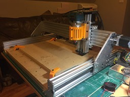
  1. Brian Popp

    Brian Popp Well-Known
    Builder

    Joined:
    Feb 27, 2017
    Messages:
    33
    Likes Received:
    57
    Brian Popp published a new build:

    Read more about this build...
     
    MikeP likes this.
  2. Davey Rance

    Builder

    Joined:
    Mar 4, 2015
    Messages:
    32
    Likes Received:
    16
    Nice Fusion Models :)
     
  3. corpore

    corpore New
    Builder

    Joined:
    Mar 31, 2017
    Messages:
    5
    Likes Received:
    1
    Hello Brian,
    ...I like the changes to the y plates. Will you be publishing the 3D files of the build? I would be very much interested (particularly in the y-plates - bec. I haven't had the time to learn the ropes of a 3D package yet).

    cheers, Fred


    ...Thanks a lot for uploading the files, it is much appreciated!
     
    #3 corpore, May 1, 2017
    Last edited: May 1, 2017
  4. Kyo

    Kyo Veteran
    Staff Member Builder Resident Builder

    Joined:
    Feb 27, 2014
    Messages:
    673
    Likes Received:
    699
    Looking good ! Your build is coming right along, you will be cutting in no time. :thumbsup:
     
  5. Brian Popp

    Brian Popp Well-Known
    Builder

    Joined:
    Feb 27, 2017
    Messages:
    33
    Likes Received:
    57
    Anybody have any ideas as to why my rig is moving so slowly?


    Max feed rate ($110/$111) is set to 1000mm/min. I didn't see anything limiting speeds in the gcode, but as you can see at the end, even non-cutting movement is slow. Amp draw is less than half an amp at 24v. I realized as I was writing this that I haven't really tweaked the amperage on the drivers (A4988).
     
  6. Gary Caruso

    Gary Caruso OpenBuilds Volunteer
    Staff Member Moderator Builder

    Joined:
    May 19, 2016
    Messages:
    1,183
    Likes Received:
    530
    post all your settings, I see many people never touch the acceleration which is set very slow stock. I have my OX HD cranked up to 700mm/sec2 and it gets up to speed fast. the way I set it is to air cut a file and turn up the acceleration until the machine is banging around, turn it down until the violence is acceptable. I know it doesn't sound scientific but really as long as you are not loosing steps you can get much more speed.
     
  7. Brian Popp

    Brian Popp Well-Known
    Builder

    Joined:
    Feb 27, 2017
    Messages:
    33
    Likes Received:
    57
    I'm using stock grbl firmware, and my settings are as follows. Really the only thing I've changed are my steps ($100-102) and the max feed rates ($110/111):

    >>> $$
    $0 = 10 (Step pulse time, microseconds)
    $1 = 25 (Step idle delay, milliseconds)
    $2 = 0 (Step pulse invert, mask)
    $3 = 0 (Step direction invert, mask)
    $4 = 0 (Invert step enable pin, boolean)
    $5 = 0 (Invert limit pins, boolean)
    $6 = 0 (Invert probe pin, boolean)
    $10 = 1 (Status report options, mask)
    $11 = 0.010 (Junction deviation, millimeters)
    $12 = 0.002 (Arc tolerance, millimeters)
    $13 = 0 (Report in inches, boolean)
    $20 = 0 (Soft limits enable, boolean)
    $21 = 0 (Hard limits enable, boolean)
    $22 = 0 (Homing cycle enable, boolean)
    $23 = 0 (Homing direction invert, mask)
    $24 = 25.000 (Homing locate feed rate, mm/min)
    $25 = 500.000 (Homing search seek rate, mm/min)
    $26 = 250 (Homing switch debounce delay, milliseconds)
    $27 = 1.000 (Homing switch pull-off distance, millimeters)
    $30 = 1000 (Maximum spindle speed, RPM)
    $31 = 0 (Minimum spindle speed, RPM)
    $32 = 0 (Laser-mode enable, boolean)
    $100 = 400.000 (X-axis travel resolution, step/mm)
    $101 = 400.000 (Y-axis travel resolution, step/mm)
    $102 = 629.920 (Z-axis travel resolution, step/mm)
    $110 = 1000.000 (X-axis maximum rate, mm/min)
    $111 = 1000.000 (Y-axis maximum rate, mm/min)
    $112 = 500.000 (Z-axis maximum rate, mm/min)
    $120 = 10.000 (X-axis acceleration, mm/sec^2)
    $121 = 10.000 (Y-axis acceleration, mm/sec^2)
    $122 = 10.000 (Z-axis acceleration, mm/sec^2)
    $130 = 200.000 (X-axis maximum travel, millimeters)
    $131 = 200.000 (Y-axis maximum travel, millimeters)
    $132 = 200.000 (Z-axis maximum travel, millimeters)


    The gcode I was printing starts out like this (exported from ArtCam):

    T1M6
    G0Z5.000
    G0X0.000Y0.000S50000M3
    G0X3.654Y-7.641Z5.000
    G1Z0.000F1000.0
    G1X3.578Y-7.615F1500.0
    X3.546Y-7.542
    Y-5.707
    X3.567Y-5.645
    X3.621Y-5.610

    Let me know if any other settings would be helpful and thanks for the help.
     
  8. Giarc

    Giarc OpenBuilds Team
    Staff Member Moderator Builder Resident Builder

    Joined:
    Jan 24, 2015
    Messages:
    2,892
    Likes Received:
    1,609
    Your acceleration may be low. Also, the movements are so small due to the size of the lines, it can never get up to 1000. Try making a big square the size of your maximum cutting area and send it at 4000 mm/min. Between 3000 and 4000 mm/min is the speed I cut most woods.
     
  9. Brian Popp

    Brian Popp Well-Known
    Builder

    Joined:
    Feb 27, 2017
    Messages:
    33
    Likes Received:
    57
    Increasing the acceleration ($120-122) made a ton of difference. It still seems a little slow, but that may just be inherent with leadscrew designs. I currently have acceleration at around 250 and was able to crank my max feed rates to 3500. Anything over that and my stepper motors start barking and not spinning. Not sure what this means? I currently have my microsteps set at 1/16, so maybe reducing that would allow me to push them faster?

     
  10. Giarc

    Giarc OpenBuilds Team
    Staff Member Moderator Builder Resident Builder

    Joined:
    Jan 24, 2015
    Messages:
    2,892
    Likes Received:
    1,609
  11. MTO

    MTO Well-Known
    Builder

    Joined:
    Dec 5, 2013
    Messages:
    35
    Likes Received:
    35
    Also, 250mm/sec2 is still kinda low. At that acceleration, it'll take about 3 seconds for the gantry to cross your table in the Y axis: 1.5 seconds to traverse 305mm accelerating up to 375mm/s, and then another 1.5 seconds deceleration. so you don't even hit 1000mm/s, let alone 3500mm/s. I dont have a recommendation, but I think I would start with something like "I want to reach top speed in 1/x'th of a second" and work out an acceleration from there. If you use 610mm/sec2, you'll traverse the entire y axis in one second, with a top speed of 305mm/s. d=u*t+0.5*a*t-squared is my ally, and a powerful ally it is. (u is initial speed, so usually, its 0)
     
  12. Anthony Bolgar

    Anthony Bolgar Journeyman
    Builder

    Joined:
    Jan 14, 2016
    Messages:
    354
    Likes Received:
    198
    How accurate is the machine using the 3D printed plates? I was wondering if I could make the build using 3D printed instead of aluminum plates.
     
  13. Brian Popp

    Brian Popp Well-Known
    Builder

    Joined:
    Feb 27, 2017
    Messages:
    33
    Likes Received:
    57
    I probably wouldn't try to launch a space shuttle with it, but it's surprisingly rigid and accurate. I haven't done any in depth testing with machining tools or anything (I'm obviously very new to this), but the few parts I've made fit perfectly. I suspect that it will eventually tear itself apart, though, so I'm very quickly trying to get all my plates cut out without putting the machine under too much stress. For this plate I used .3mm cut depth, around 250mm/min (very slow), and I think around 15-18k RPM (around 2 on my Makita router).This is 1/4" 6061 aluminum.

    [​IMG]
    [​IMG]

    I do have two problems right now that I'm trying to work through. I don't think they are plate related, but they might be. The first is that my Z axis seems to plunge inconsistently. The bed is relatively level and the gantry is level with it, but it consistently cuts deeper the further right on the X axis I go. Inevitably if I put my z axis on the top of the stock, set zero, home, and then return to zero, my cutter try to dig 1-2mm into the plate. It almost never goes back to exactly the same z position (the other two axis are spot-on).

    The other problem is that I'm getting a lot of resonance at high RPMs. I tried to cut some MDF last night and it was mind-piercing. I think this is caused by looseness in my Z axis gantry, but when I tighten the mini v-wheels down, the wheels stop rolling and instead drag. This causes a stutter since the weight of the router is putting uneven forces on the gantry plate.

    The CBeam design with the mini wheels for the z axis is kind of clever, but so far I'm not really a fan. It takes up too much space and it really seems unbalanced and has a lot of deflection. I'm definitely going to spend some time trying to improve it.. either by fixing my mistakes or redesigning it entirely.
     
    #13 Brian Popp, May 18, 2017
    Last edited: May 18, 2017
    Jack Ethan Schlein likes this.
  14. Giarc

    Giarc OpenBuilds Team
    Staff Member Moderator Builder Resident Builder

    Joined:
    Jan 24, 2015
    Messages:
    2,892
    Likes Received:
    1,609
    Is your z motor always powered when your machine is on? I had the grbl settings set where mine was not (can't remember which one of the top of my head). It would slowly lower over time.
     
  15. MTO

    MTO Well-Known
    Builder

    Joined:
    Dec 5, 2013
    Messages:
    35
    Likes Received:
    35
    He has $1 set to 25 milliseconds, so the motor will power down after 25ms. I guess it should be set to 255 so that it doesn't ever idle the z motor...

    I'm gonna check, but I wonder if GRBL 1.1 has per-axis settings.
     
  16. MTO

    MTO Well-Known
    Builder

    Joined:
    Dec 5, 2013
    Messages:
    35
    Likes Received:
    35
    On acceleration. GRBL 1.1 manuals say:
    Like the max rate setting, the simplest way to determine the values for this setting is to individually test each axis with slowly increasing values until the motor stalls. Then finalize your acceleration setting with a value 10-20% below this absolute max value. This should account for wear, friction, and mass inertia. We highly recommend that you dry test some G-code programs with your new settings before committing to them. Sometimes the loading on your machine is different when moving in all axes together.​

    on stepper idle timer:
    The stepper idle lock time is the time length Grbl will keep the steppers locked before disabling. Depending on the system, you can set this to zero and disable it. On others, you may need 25-50 milliseconds to make sure your axes come to a complete stop before disabling. This is to help account for machine motors that do not like to be left on for long periods of time without doing something. Also, keep in mind that some stepper drivers don't remember which micro step they stopped on, so when you re-enable, you may witness some 'lost' steps due to this. In this case, just keep your steppers enabled via $1=255.
    So it doesn't look like GRBL 1.1 has changed much on this front.

     
  17. Brian Popp

    Brian Popp Well-Known
    Builder

    Joined:
    Feb 27, 2017
    Messages:
    33
    Likes Received:
    57
    I tried the $1=255, but didn't notice any difference. I did a little more experimenting, and what is happening is that each time the Z axis moves up and then back down, it seems to lose between 1 and 2mm. I created a part with 10 slots, and each slot is slightly deeper than the next by about 1-2mm. I typically noticed this when the cuts went from left to right, but that was just a coincidence. Cuts along the Y axis do exactly the same thing.
     
  18. Anthony Bolgar

    Anthony Bolgar Journeyman
    Builder

    Joined:
    Jan 14, 2016
    Messages:
    354
    Likes Received:
    198
    Try it with $1=0 This will keep the Z axis powered all the time.
     
  19. Brian Popp

    Brian Popp Well-Known
    Builder

    Joined:
    Feb 27, 2017
    Messages:
    33
    Likes Received:
    57
    Looks like I was losing steps on the retract. I changed the gearing and adjusted my microsteps down and it appears to be holding the depth correctly now. The first two columns were before the change, and the last column is after:

    [​IMG]
     
    Kyo and MTO like this.
  20. Anthony Bolgar

    Anthony Bolgar Journeyman
    Builder

    Joined:
    Jan 14, 2016
    Messages:
    354
    Likes Received:
    198
    Glad you solved the issue.
     
  21. ApexPredatorEffects

    Builder

    Joined:
    Apr 20, 2017
    Messages:
    7
    Likes Received:
    2
    Hi, I'm noob to the cnc world but planning to build a sphinx like your with 1000x1000 xy axis and maybe a longer z axis too, anyway I was reading your axis description and wondering where exactly the additional rail goes, I can't exactly figure out where it is, maybe could you take pictures all around your sphinx? I suppose the rail is on the rear side isn't it?

    Thanks a Lot ^_^
     
  22. Brian Popp

    Brian Popp Well-Known
    Builder

    Joined:
    Feb 27, 2017
    Messages:
    33
    Likes Received:
    57
    No, the support rail goes underneath the X axis cbeam (slightly darker rail in the shot below):

    [​IMG]

    I joined the two together with blind joints. I honestly don't know if this extra reinforcement is even required. Those C-Beams are already pretty beefy. I'd talk to one of the guys that have built 1000mm CBeam machines and ask if they've noticed any deflection in the middle. I honestly doubt it, but for $15 bucks and no negative impact to the design, I thought it was easily worth it. It also has the added advantage of moving the wheels further apart, adding a little extra weight, and increasing the surface area where it joins to the Z axis cbeam.

    Just throwing this out there, but what might be interesting would be to move the CBeam down to where I have the 20x40, and then replace the 20x40 with a 20x60 and move it above the cbeam. This would allow you to use 3 rows of wheels instead of two and that would definitely have a positive impact on reducing z axis torquing. You could also put a 20x20 next to the bottom cbeam to allow for 9 wheels on the bottom. I'll mock that up when I get home tonight and upload some more plates if it looks like it would work out.

    By the way, I mentioned earlier that my 3d printed wheels didn't work out. That's not entirely true. I am using using 3d printed wheels (polycarbonate) for the large wheels and it seems to be working fine. You can see them above in the Z axis gantry shot.
     
    #22 Brian Popp, May 22, 2017
    Last edited: May 22, 2017
  23. Brian Popp

    Brian Popp Well-Known
    Builder

    Joined:
    Feb 27, 2017
    Messages:
    33
    Likes Received:
    57
    Justin, I beefed up the design a little bit and it's actually working much better. Aluminum would be better, but so far it's taken whatever I've thrown at it:

    [​IMG]

    I did another plate last night and got no chatter and was able to double my cutting speeds (450mm/min+). Halfway through I started boosting the feed speed to 200% and didn't seem to have any issues. I'm going to experiment a little more tonight and see how much faster I can go.

    You can see I have my router at the top and I'm having to cut way down at the bottom of the Z axis, though. When I rebuild the X/Z axis, I'm going to mount the Z axis lower so that I get more range and can mount the router further down. It would be much better if I could choke up closer to the bit.
     
    #23 Brian Popp, May 22, 2017
    Last edited: May 22, 2017
  24. ApexPredatorEffects

    Builder

    Joined:
    Apr 20, 2017
    Messages:
    7
    Likes Received:
    2
    Thanks for your explanation, I'll wait to see your 20x40 / 20x60 mod ^_^ also considering that I wish to use at l'est a 500mm z axis.

    May I ask a question, have you considered to add some sort of cover plate on the upper wheels on y axis? Something to shield from milling debris, like the ooznest OX X shaped plates
     
  25. Brian Popp

    Brian Popp Well-Known
    Builder

    Joined:
    Feb 27, 2017
    Messages:
    33
    Likes Received:
    57
    Yeah, I've got this thing in my office right now, so dust/debris management is high on my list. I'm planning on attaching some plexiglass to the cbeams left and right of the cutter. Honestly it's more about making it easier to keep clean than protecting the wheels. In my experience, stuff just falls harmlessly into the slots of the cbeam. I also plan on adding a dust shoe at some point soon.

    Just curious, why do you want a longer z axis? I never make it more than 6" up my z axis and can't imagine why I ever would.
     
  26. ApexPredatorEffects

    Builder

    Joined:
    Apr 20, 2017
    Messages:
    7
    Likes Received:
    2
    Well I have to check the right z I need but the reason is put a 15cm diecast Hammond case under it in order to drill it and/or cut part of it's side
     
  27. Brian Popp

    Brian Popp Well-Known
    Builder

    Joined:
    Feb 27, 2017
    Messages:
    33
    Likes Received:
    57
    Problem you will have with the Sphinx design (and honestly, most designs) is that the bottom of the Z axis is going to collide with any tall object you would want to cut unless it just happens to be along a 1" perimeter of the object. If you look at the shot above, that black plate at the bottom of the Z axis does not move. You *could* permanently raise the Z axis up a little bit, but it's going to make working with shorter end mills more painful (you'll have to use a tall wasteboard or vice). Either way, unless I'm missing something, with this design you will never get more clearance than the bottom of the X axis (in my case, that's around 125mm from the table).
     
  28. Rick 2.0

    Rick 2.0 OpenBuilds Team
    Staff Member Moderator Builder Resident Builder

    Joined:
    Dec 20, 2013
    Messages:
    2,852
    Likes Received:
    1,524
    You can always turn the Z-axis around and let the whole assembly move up and down. This resolves the clearance issue. It will however create a little more slop in the system due to the increased distance from the bit to the narrow spaced wheels so if you do this, consider upgrading to a plate that grips the outer edges of the c-beam like the xl gantry plate.
     
  29. ApexPredatorEffects

    Builder

    Joined:
    Apr 20, 2017
    Messages:
    7
    Likes Received:
    2
    Think outside the square, why I have to increase z when I can build a table with an hole under the sphinx and align it with the free area of the frame in order to perform what I need?
     
    GrayUK and MTO like this.
  30. Brian Popp

    Brian Popp Well-Known
    Builder

    Joined:
    Feb 27, 2017
    Messages:
    33
    Likes Received:
    57
    Thanks Rick. I'm embarrassed to say I didn't even consider that option. I'll definitely check out the XL gantry plate. I like the aesthetics of the small wheels, but I've had constant issues with slop.
     

Share This Page

  1. This site uses cookies to help personalise content, tailor your experience and to keep you logged in if you register.
    By continuing to use this site, you are consenting to our use of cookies.
    Dismiss Notice