Welcome to Our Community

Some features disabled for guests. Register Today.

Rotary Axis OX Derivitive

Discussion in 'CNC Lathes' started by dougsnash, Dec 7, 2014.

  1. dougsnash

    dougsnash New
    Builder

    Joined:
    Sep 13, 2014
    Messages:
    29
    Likes Received:
    38
    John Furjanic likes this.
  2. dougsnash

    dougsnash New
    Builder

    Joined:
    Sep 13, 2014
    Messages:
    29
    Likes Received:
    38
    Design work is continuing for my Roto-Ox CNC machine. I have the OX CNC X/Z plates modified to use 20x80 V-Slot rail and have done the preliminary design work on the gantry plates which will support the ends of the machine. While the end plates appear to be serviceable in the sketchup drawing, I am not sure about the room I have left between the face of the Z-Axis and the centerline of the A-Axis (Y-Axis adjustment). Until I can mock-up the prototype with an actual router and mount I won't be sure how much space will be required for the Y-Axis. Also, I do not like the long single slot I have left for fine tuning the Y-Axis spacing and will likely break it up into two or four shorter slots once I figure out exactly where the bolt holes need to be.
     
  3. dougsnash

    dougsnash New
    Builder

    Joined:
    Sep 13, 2014
    Messages:
    29
    Likes Received:
    38
    Most of the parts are on order. I hope to be able to start building the prototype between Christmas and New Years
     
  4. Carl Stoner

    Builder

    Joined:
    Nov 2, 2014
    Messages:
    9
    Likes Received:
    0
    I have been watching your progress, hope you get that chance to work on it more over the holidays.

    I am also building a CNC lathe (for wood) I'm planning to make use of the existing lathe, so that I can use all the features (chuck, vacuum chuck, tail stock, etc). To do this it will mount to the bed of either of my wood lathes.

    I am also using the OX X / Z plates to mount to a (crude) structure. I'm designing on the fly, expecting to learn the weak points and make changes before the final build.

    Your use of 20x80 instead of 20x60 sounds like a good idea, I'll eventually need to do that also. For now the double 20 x60 will only span about 750, so I hope it will be ok for a test build.

    Eager to follow your progress
     
  5. dougsnash

    dougsnash New
    Builder

    Joined:
    Sep 13, 2014
    Messages:
    29
    Likes Received:
    38
    Hi Carl, nice to know I'm not the only one thinking of making spindles. Now that I have the basic design laid out in Sketchup I am starting to think about adding a short stroke Y-Axis to the Roto-OX. By adding a derivative of the Z-Axis to each of the end plates I would end up with far more flexibility in what the machine would be capable of making. I might try making up a set of plates as I have them designed now and see how they work before trying to get any fancier.

    Doug M
     
  6. SlyClockWerkz

    SlyClockWerkz Well-Known
    Builder

    Joined:
    Feb 26, 2014
    Messages:
    94
    Likes Received:
    34
    Looks cool :)
    Looking forward to some pics/videos
     
  7. dougsnash

    dougsnash New
    Builder

    Joined:
    Sep 13, 2014
    Messages:
    29
    Likes Received:
    38
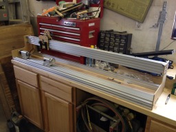
    My build is progressing. I had a few minor tuning challenges with my OX CNC which made the cutting of the sample plates a bit time consuming but now have a set of plates made to build up the prototype RotoOx. I have the X-Axis installed and the beam for the A-Axis but hit a small snag when I went to install the 20x40 stiffening rails. While the 20x80 rails are exactly 1500mm long, the three 20x40 rails vary in length by between 5-8mm oversized. Fortunately, the rail that is 8mm too long has a tap broken off in the end of it and hopefully I'll be able to extract it during the trimming process.

    My plans were to use 6.0mm hardboard for prototyping purposes so I was not wasting expensive 1/4" aluminum plate figuring things out. I figured the hardboard would work for layout but would not be up to supporting a running machine. Although I am not yet done assembling the machine, I am surprised how stiff it is becoming even being build out of inexpensive compressed sawdust. I doubt the hardboard will stand up to much abuse but at least I should be able to make the machine run a bit before upgrading to aluminum plates.

    I'll snap some pictures once I get the 20x40 rails installed you can see how it is coming together.
     
  8. mihaib

    mihaib New
    Builder

    Joined:
    Feb 24, 2014
    Messages:
    6
    Likes Received:
    2
    Nice design . Hope to see-it in action , ans some photos with machine. Can you post dxf file with the plates ?
     
  9. dougsnash

    dougsnash New
    Builder

    Joined:
    Sep 13, 2014
    Messages:
    29
    Likes Received:
    38
    Most of the mechanical assembly of the Roto-OX is complete with the exception of the Z-Axis due to some parts on backorder. I am pleasantly surprised at how stiff the machine is lengthwise even with the hardboard ends. The stepper motor for the X-Axis has some play in it so will not likely stand up to much use as is but should be solid enough to at least make a few test cuts. I will update as the build progresses. Roto-OX Under Construction.JPG
     
  10. Robert Hummel

    Robert Hummel Custom Builder
    Moderator

    Joined:
    Nov 14, 2013
    Messages:
    978
    Likes Received:
    714
    Are you just prototyping with the wood plates and then going aluminum ?
     
  11. dougsnash

    dougsnash New
    Builder

    Joined:
    Sep 13, 2014
    Messages:
    29
    Likes Received:
    38
    Yes, the wood is just for prototyping. I am hoping that the wood will stand up long enough to cut a piece or two to prove the concept of the Roto-OX but I am not expecting any more from it than that. I have the aluminum to make the plates already but my OX CNC is not working reliably enough yet to cut it. I did some tuning on the OX yesterday so maybe it will be up to cutting aluminum when I'm ready for the final plates. I want to be absolutely sure the OX can handle the 1/4" aluminum before cutting into a $100.00 plus piece of metal.
     
  12. Robert Hummel

    Robert Hummel Custom Builder
    Moderator

    Joined:
    Nov 14, 2013
    Messages:
    978
    Likes Received:
    714
    Where are you located in canada?
    I would be more then happy to help with your build my friend :)
    I see your not using my plate files or at least not the front as it looks to be the new larger plate.
    Let me know as I may just have some leftover aluminum to cut you a new set ;)
    How large are the side plates ? Width by height
     
  13. dougsnash

    dougsnash New
    Builder

    Joined:
    Sep 13, 2014
    Messages:
    29
    Likes Received:
    38
    Robert, I'm in the southwestern corner of Northwestern Ontario.

    The X and Z plates that I have cut are modified versions of the new eight wheel plated listed for the original OX. The main modification I have made to the X and Z plates was to stretch the plates twenty additional millimeters to accommodate 20x80 V-Rail for the X-Axis instead of the original 20x60 used on the OX. The prototyping I have done suggests 21mm might have been a better plan as the fit over the double 20x80 rails is a bit tight. The end plates are 295mm wide by 247mm tall but these dimensions will likely change a bit as the design matures. I have already started to mentally design a Y-Axis assembly to add to the end plates to offer true 4 axis spindle machining. The Y-Axis will use two short stroke ACME threaded assemblies to move the centre of the A-Axis fore and aft under the router bit. Since the radial capacity of the spindle assembly is only 49mm, I will only need a Y-Axis stroke of 100mm to be able to route a flat onto any portion of the work piece.

    Unfortunately, I am almost as far as I can go with this project until some more parts come back into stock at the Openbuilds Store. Mark says the stock will be replenished sometime this coming week so hopefully I'll be making chips with the Roto-Ox soon.

    Doug M
     
  14. Robert Hummel

    Robert Hummel Custom Builder
    Moderator

    Joined:
    Nov 14, 2013
    Messages:
    978
    Likes Received:
    714
    With the hole spacing already set in the original plate file no more then 20mm should be added.
    Why it seems loose I'm not sure o_O
    Have you adjusted the eccentrics all the way?
    I can mod my x plate if you like and see how it fits on some 20x80 I have here also add an extra set of holes so you can use 8 wheels
    Are you using 20x60 for the Z or 20x80?
     
  15. dougsnash

    dougsnash New
    Builder

    Joined:
    Sep 13, 2014
    Messages:
    29
    Likes Received:
    38
    It's Alive!!! Well sort of, at least.

    I did a quick and dirty installation of my new TinyG controller board yesterday and have the X-Axis working well (Mainly because I was able to re-use the tuning numbers for my OX CNC). The A-Axis will move but I have had to map it to the Y-Axis because TGFX doesn't have a jog control for the A-Axis. Still, I am able to make the X carriage move side to side and have the A-Axis spin a block of wood I have clamped in the chuck so I call that progress. There is not much information on the TinyG wiki about tuning a rotary axis so I am going to have to do some experimenting to get the A-Axis functioning as it should.

    Robert, I have adjusted the eccentrics to their minimum tension but still found the spacing around the X-Axis beams a bit tight. I can work with the tension as I have it for prototyping but would like to have some adjustment in the final version. The currently installed X/Z plates are v0.2 which included an additional 0.5mm of clearance and they are better than the v0.1 plates which fit but were way too tight. That is why I am leaning to use 1.0mm as the additional measurement from my original design to allow for some wheel tension adjustment. I think I am going to take some detailed measurements of what I physically have and modify my plates accordingly. There is no sense repeatedly tweaking the design based on guesses when I have a built assembly to measure.

    I am using 20X60 for the Z-Axis. In the picture above, if you look behind the machine you can see a piece of black 20x60 which will be used for the Z rail. I had forgotten to order 45mm bolts for the Z-Axis when I ordered the parts for this build so I cannot mount the Z-Axis wheels till my next parts order arrives. Also , the Openbuilds store is out of ACME threaded rod so I can't install the Z rail even if I did have the wheels. Supposedly more ACME rod will be arriving soon so hopefully I'll be able to finish the build up and give the machine a try.

    Thanks for following my progress.

    Doug M
     
    GrayUK, Mark Carew and Robert Hummel like this.
  16. Carl Stoner

    Builder

    Joined:
    Nov 2, 2014
    Messages:
    9
    Likes Received:
    0
    Looks great Doug. I've been working on my design also, the main differences in the final design will be that mine will mount to the bed of a regular wood lathe. Since I'm mostly a turner, I have 2 lathes, with several chucks, and other attachments. Also I have a stepper controlling the rotation, so I plan to devise some way to prevent it from being attached if the lathe motor is not disabled (belts off, or unplugged). I will also have the option to use the lathe motor instead of the stepper for spindles not needing flutes, spirals, etc.

    I have built an x-z assembly, the same as I used for my version of the OX. First I built a crude wood frame, secured to the lathe bed, with 2 triangles made from 2x4s and suspended the double 20x60 from it with home made aluminum brackets. I was able to adjust it to make a few dowels, just by jogging ( I'm have Mach3 on an old XP computer)

    All worked as planned, now I have a beautiful 16" perfectly uniform dowel. It did shake some, and showed that the wood frame, even if rebuilt from steel, is probably to large to be stable.

    Today I made a much smaller frame from scrap 1" square steel tubing, from old cheap commercial shelving. It's very compact, and with the former Z axis now horizontal. Again, a crude experiment, but I'm better at designing by making, I miss to many problems when I draw plans.

    This design looks very simple and easy to rebuild stronger. The steel was 1" square, only 1/16" wall. If I use 1/8", it should have no flex, but I now see how I could build it from 20x80 and 20x60, and believe it will be very sturdy either way.

    Mine doesn't look as nice as yours, but hopefully we will both be making round stuff soon!
     
  17. dougsnash

    dougsnash New
    Builder

    Joined:
    Sep 13, 2014
    Messages:
    29
    Likes Received:
    38
    Thanks Carl. I am a bit worried about rigidity on the horizontal 20x80 rail which has the head stock and tail stock mounted to it. The end of the rail is well supported by the endplates but I am worried the rail will flex a bit if the tailstock is mounted in the middle. I have a couple of ideas which will stiffen the horizontal 20x80 rail if vibration becomes an issue but I won't know how bad the shake will be until I get the rest of the parts assembled. I don't want to get too carried away designing solutions to a problem which may or may not be that big of a deal.
     
  18. Carl Stoner

    Builder

    Joined:
    Nov 2, 2014
    Messages:
    9
    Likes Received:
    0
    That makes sense to me Doug, the 20x80 rail that your head and tail stock are mounted to are the equivalent of the heavy rigid cast iron bed of a traditional lathe. Although I admire the elegance of engineering a machine to do more with less, it seems to me that you can add strength by using a heavy piece of scrap steel as part of the bench it sits on, and bolt the 20x80 to it. I recently found square steel tubing about 3x3 with a 1/4" wall for pennies at a scrap dealer. You could drill 5mm holes in the top, 15mm or larger opposite for access, and use t bolts to fasten the 20x80.

    A few thoughts about the need for more rigidity, using a wood lathe is like holding a saw in both hands, while a huge machine moves the 4x4 oak beam back and forth. That's why my router table weighs about 60 lbs., while my large lathe weighs 600 lbs. The cutting force of the router comes from the cutter, not the piece being cut.

    My first build had the very rigid lathe bed, but with the X-Z mounted on a large wood frame. I got enough vibration to require very slow movement of the router, and very shallow cuts. Now with a very compact (scrap) steel frame, should improve that.

    Another future concern is that even with the head and tail stock very rigid, and the X-Z very rigid, if you are turning a wood spindle, the longer and thinner it is, the more likely you will have vibration in the spindle itself. Near the center it will start to vibrate, and if you are just making a straight dowel, the center will look like fine threads.

    If you are not familiar with traditional turning, long thin spindles need support in the center. Usually a heavy frame mounted to the bed, with 3 adjustable roller skate wheels surrounding the spindle ("Spindle Steady"). Hand turning, you would shape close to it, then move it to a finished section a few inches away to finish. If we want to make spindles with our CNCs, we may need this support, and stop the cut after cutting close to it, to move the support. If we're really ambitious, we'll make a similar support that moves with the X, and wheels that adjust inward as the piece becomes smaller in diameter.

    I'm having so much fun pretending to be an engineer!
     
  19. dougsnash

    dougsnash New
    Builder

    Joined:
    Sep 13, 2014
    Messages:
    29
    Likes Received:
    38
    A progress update.

    A small order of parts arrived on Friday which has allowed me to make a bit more progress on my Roto-OX. I have installed the wheels and cut the piece of 20X60 rail for the Z-Axis. I cannot finish the Z-Axis completely because I don't have the necessary ACME threaded rod yet (on order). I also have begun piecing together the motor assemblies for the Y-Axis modification I have planned. I can see that there will be some minor modifications necessary to the end plates to make the Y-Axis assembly work but I kind of expected that from the beginning.

    A question for anyone following this build. Have any of you got any advice on how to connect an eight lead stepper motor to a four lead stepper driver? I understand both the four and six lead installations but the recycled NEMA 17 motor I am trying to use for my Z-Axis has eight wires. Essentially, two sets of leads are going to have to be connected in parallel but I have no idea how to tell which lead sets need to be paired.

    Work on the project is likely going to stall for a couple of weeks due to my work schedule but I will keep plugging away at the design.

    Doug M
     
  20. Serge E.

    Serge E. Journeyman
    Builder

    Joined:
    May 6, 2014
    Messages:
    730
    Likes Received:
    251
    This might help in figuring it out (found over at http://www.selene.co). They also have a few other pages explaining voltage, amps and torque ...

    Series Winding

    [​IMG]

    or configured as

    Parallel Winding
    [​IMG]
     
  21. SlyClockWerkz

    SlyClockWerkz Well-Known
    Builder

    Joined:
    Feb 26, 2014
    Messages:
    94
    Likes Received:
    34
    Typically you use a chart like posted above alongside a multimeter measuring for resistance across leads to narrow down which lead is which. On an 8 lead stepper you will have 4 common wires and an A a B b
    thats what my steppers are like at least
     
  22. dddman

    dddman Journeyman
    Builder

    Joined:
    Mar 2, 2014
    Messages:
    468
    Likes Received:
    187
  23. dougsnash

    dougsnash New
    Builder

    Joined:
    Sep 13, 2014
    Messages:
    29
    Likes Received:
    38
    Thanks dddman. I've read something similar someplace but don't remember exactly where so the link was useful to me. The issue I have is the motor has eight coils and four wire pairs so the connection of opposite coils is taken care of internally. I need to figure out an easy way to detect which wire is connected to which coil so I can wire every second coil together in parallel for connection to the driver output. I took the motor apart the other day to see if I could identify which wire went to which coil but due to how the wires connect to the coils, I cannot specifically see which color wire goes where.

    At the end of it, I am not beyond spending the $15.00 or so for a new NEMA 17 motor. I figured I would re-purpose this salvaged motor if possible but I'm not going to waste too much effort trying to re-invent the stepper motor to save $15.00.

    Thanks for your feedback.

    Doug M
     
  24. dougsnash

    dougsnash New
    Builder

    Joined:
    Sep 13, 2014
    Messages:
    29
    Likes Received:
    38
    For those of us who are interested in designing our own wheel plates, I have taken a few measurements of the V-Slot rails and standard wheels. I do not know if it makes any difference but I have noted the colour of the rail I measured in brackets.

    20X80 = 80.0mm (silver)
    20X60 = 59.8mm (black)
    20X40 = 40.0mm (silver)
    20X20 = 19.9mm (silver)

    The diameter of a standard black wheel (not the newer clear heavy duty one) is 23.9mm
    The distance between the top of the wheel and the edge of a v-slot rail is 21.7mm (as close as I could measure).
    By calculating the difference between the two above measurements, I get a wheel axle center point of 9.75mm from the surface of the V-Slot rail.

    Keep in mind that my shop was about 0 degrees F when I took these measurements so temperature may have had an effect on the accuracy of my measuring.
     
  25. dougsnash

    dougsnash New
    Builder

    Joined:
    Sep 13, 2014
    Messages:
    29
    Likes Received:
    38
    All I did was take the measurements, only took a couple of minutes. I'm Canadian so 0 F is almost warm in January.
     
    Thamli likes this.
  26. dougsnash

    dougsnash New
    Builder

    Joined:
    Sep 13, 2014
    Messages:
    29
    Likes Received:
    38
    A progress update:

    I have spent much of the last two months traveling for work so I haven't had much of a chance to work on the Roto-OX. The ACME threaded rods that I had on order came in and I have completed assembling the Z-Axis. I decided to spend the $10.00 or so and buy a new Z-Axis motor and have it mounted as well. Unfortunately, I haven't had a chance to run any testing on the system yet. I will let everyone know when I get a chance to wrench on the Roto-OX again.
     
    kmc likes this.
  27. Mark Carew

    Mark Carew OpenBuilds Team
    Staff Member Moderator Builder Resident Builder

    Joined:
    Jun 28, 2013
    Messages:
    2,741
    Likes Received:
    2,407
    Looking forward to it Doug, keep up the good work. :thumbsup:
     
  28. TadB

    TadB New
    Builder

    Joined:
    Apr 20, 2015
    Messages:
    3
    Likes Received:
    2
    I am looking forward to seeing video of your build I have been looking for a way to automate my jet mini lathe. I saw some one else was working along these same lines in the comments would love to see some pics of that project also.
     
  29. dougsnash

    dougsnash New
    Builder

    Joined:
    Sep 13, 2014
    Messages:
    29
    Likes Received:
    38
    Anybody have a suggestion where I can get a router mount that will fit a 89mm diameter router? The router mount is kind of the last thing I need to sort out before I can start testing my creation.
     
  30. Rick 2.0

    Rick 2.0 OpenBuilds Team
    Staff Member Moderator Builder Resident Builder

    Joined:
    Dec 20, 2013
    Messages:
    2,852
    Likes Received:
    1,524
    That's considerably bigger than most are dealing with here. Best suggestion would be to check with @Chris Laidlaw for a custom build.
     

Share This Page

  1. This site uses cookies to help personalise content, tailor your experience and to keep you logged in if you register.
    By continuing to use this site, you are consenting to our use of cookies.
    Dismiss Notice