Welcome to Our Community

Some features disabled for guests. Register Today.

RiNo Route

Discussion in 'CNC Mills/Routers' started by Steven Sampson, Sep 15, 2015.

  1. Steven Sampson

    Builder

    Joined:
    Jun 26, 2015
    Messages:
    12
    Likes Received:
    20
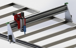
    Steven Sampson published a new build:

    Read more about this build...
     
  2. Steven Sampson

    Builder

    Joined:
    Jun 26, 2015
    Messages:
    12
    Likes Received:
    20
    That's true but I have the luxury of doing it for my job, not just my free time so I think it can be done.... As long as everything shows up. I decided on the gear reducers to take me from 42 steps/in to 257 steps/in, not for speed reasons.

    The rolling wood base is done and the table top steel is purchased and I am about to start welding.
     
  3. Steven Sampson

    Builder

    Joined:
    Jun 26, 2015
    Messages:
    12
    Likes Received:
    20
    Welded the Table Yesterday
     

    Attached Files:

  4. Ronald van Arkel

    Staff Member Builder Resident Builder

    Joined:
    May 7, 2014
    Messages:
    472
    Likes Received:
    245
    Hello Steven,

    How is your build of this large monster coming along?

    -Ronald
     
  5. Jonny Norris

    Jonny Norris Well-Known
    Builder

    Joined:
    Aug 17, 2014
    Messages:
    495
    Likes Received:
    95
    Planatary gearboxes over microstepping is definitely the way to go, increase the steps per without being detrimental to torque as you would using large amounts of microstepping.

    Mentioning your budget, you need to be a little cautious with cheap planatary gearboxes as they can suffer from excessive backlash. Something to test for before you fit them. Can I ask why just 4:1? Do you have any other ratios available to you? As you could get that ratio easily with some plain gearing or pulleys. On my 8x4 I use 20:1 on a 250kg gantry and get 6m/min (stalls at 8) with a 3nm motor.

    I'm liking the design tho, good job. however have you looked into nylon racks? A bit of an upgrade to belt and if you shop around, a fair bit cheaper than steel. R&p's would be better suited to the gearbox. And would avoid the dreaded belt stretch.
     
  6. Steven Sampson

    Builder

    Joined:
    Jun 26, 2015
    Messages:
    12
    Likes Received:
    20
    The build goes well. I have one more operation on the milling machine to bring the gantry beam down a few mm in length. after that I can assemble everything at which point I am just waiting on the stepper motors and drivers. Steppers were back ordered. I have a ton of pictures I will update very soon. I feel pretty good about the whole thing. I have had a a couple hiccups. The big one is the gantry plate warped a bit under the stress of the aluminum welding. Not the heat but the shrinkage during cool down. I have not worked around that yet. I wouldn't even be an issue but my tolerances were pretty small.

    Jonny - I chose 4:1 because the efficiency drop was so small and that was all I needed to get down to a reasonable step/inch. I'm not sure what you mean by racks... I chose belts for cost reasons. Rack and pinion is quite expensive. I'm hoping the 25mm belt will be wide enough to last a while. also i have custom made belt tensioners. Hoping that I can compensate as things move around.

    Pics soon.
     
    #6 Steven Sampson, Oct 22, 2015
    Last edited: Oct 22, 2015
  7. Jonny Norris

    Jonny Norris Well-Known
    Builder

    Joined:
    Aug 17, 2014
    Messages:
    495
    Likes Received:
    95
    here's a link to something similar to what i had in mind.. its abit more expensive than the type i was thinking of but cant for the life of me find it now, but cheaper than steel.

    Flexible Racks - Flexible Rack, 0.8 Mod (32DP)

    i think with the holders or just the clamps you can join them. not the one shown used to make a pinion there are some other accessories for these that dont seem to be listed on that site.

    Though hadn't realised it was 25mm wide belt you were using :duh: when i wrote that.

    savage news about the gantry, could you unbend it with a vice at the same time weld a thin length at 90 degrees on the reverse side to pull it back?
     
    #7 Jonny Norris, Oct 22, 2015
    Last edited: Oct 22, 2015
  8. Steven Sampson

    Builder

    Joined:
    Jun 26, 2015
    Messages:
    12
    Likes Received:
    20
    Ohhh.. Yah. I was actually staring at the belt and pulleys the other day and thought "You could almost make a rack and pinion out of this..." That's a very interesting idea. 2 meters for $81 isn't bad either.

    I've already tried one fix to the gantry. I cute it and pulled it back to give me a 1mm gap in the positive, then welded it and the shrinkage still pulled it back to 2mm leaving me with a 1mm in the opposite direction.
     
  9. Jonny Norris

    Jonny Norris Well-Known
    Builder

    Joined:
    Aug 17, 2014
    Messages:
    495
    Likes Received:
    95
    Maybe braising is the way to go if you need to repeat.

    you should be able to get over that with shims, if it's where the linear bearings are, or is it applying preload to the bearings by squashing them at all?

    I had this problem at one point, made it run rough, fortunely I designed 2mm spacers to just had to swap out for .75 shims.

    might be an idea to clamp a long straight edge, longer the better, to the plate when assembled so that its flush with one side of the plate and sticking out the other side. Measure across to opposite side of opposite plate. And repeat for same side on other plate, see if they measure square, just in case that bend is effecting the 90degree angle of plate to the axis. If so then you can work out which one is doing it just by measuring diagonally from corner of straight edge to where the end of axis meets opposite plate.

    If you want to get really accurate, clamp your vernier or dri to a bar so it's long enough instead of tape, zero for one distance, Just make sure the gaugr doesn't move on the bar.
     
  10. Steven Sampson

    Builder

    Joined:
    Jun 26, 2015
    Messages:
    12
    Likes Received:
    20
  11. Steven Sampson

    Builder

    Joined:
    Jun 26, 2015
    Messages:
    12
    Likes Received:
    20

    Here is the schematic for the router finished yesterday. The wiring is started but I'm waiting on a few things to show up.

    Any comments or suggestions are welcome.

    UPDATE: 12/14/15.. Updated Version of schematic uploaded. on error found and color coding added to axis
    UPDATE: 1/5/17 Updated Version of Schematic uploaded. Schematic corrected for actual changes made upon completion of the build. PWM spindle control not used, potentiometer used instead. USB cable removed, 12V power to Break Out Board used instead.
     
    #11 Steven Sampson, Dec 9, 2015
    Last edited: Jan 5, 2017
  12. Steven Sampson

    Builder

    Joined:
    Jun 26, 2015
    Messages:
    12
    Likes Received:
    20
  13. Rick 2.0

    Rick 2.0 OpenBuilds Team
    Staff Member Moderator Builder Resident Builder

    Joined:
    Dec 20, 2013
    Messages:
    2,889
    Likes Received:
    1,545
    Steven, can you offer an explanation of the smoothing capacitors, their purpose, and how such a thing would be sized?

    Thanks,
    Rick
     
  14. Steven Sampson

    Builder

    Joined:
    Jun 26, 2015
    Messages:
    12
    Likes Received:
    20
    Smoothing capacitors would typically be used to help in keeping a voltage at a steady state. If you think of a graph of voltage over time any dips in voltage would be seen as a wiggly line. The smoothing capacitors smooth out this line... i.e. help to keep the voltage steady, hence the name smoothing capacitor. In this case they are there to act as a sort of instantaneous battery backup. Under times of super heavy load on the motors they provide extra energy. When there is a drop in voltage they supply energy to prevent that drop. If you have a nice power supply they should not be necessary but I put them in mostly as a just in case. I have no idea if they are needed in my case but better safe than sorry. In a case where they were needed but not available the following would happen: the voltage would drop in the line which would decrease the amount of magnetism in the motors windings. This equates to a drop in the holding/moving power of the motor. In the case of an extreme drop the motor would slip a tooth and would then be off by one, or more steps for the rest of the job. In a machine with encoders, it could detect the error and fix it.

    This kind of thing is very popular in super high end car stereos. When a super heavy bass note hits, often the battery and the alternator are unable to supply the needed current and the capacitor steps in to help. As for determining their size I honestly can't remember the specifics. I just did some googling to refresh my memory and the basic is that your capacitance is the product of The maximum amount of current (all your motors at 100%) and the maximum amount of time the voltage drop will occur within, divided by the maximum allowable voltage drop. In my case if I was limited to a 1% drop or 3.6 Volts, with a maximum draw of 15 amps over a period of time of one micro second I would want a capacitance of .041 Farads. My two capacitors are only .02 Farads so honestly it should only be able to deliver 7 amps, or conversely if you maximum voltage drop was 7 then it could supply the needed current. Having any smoothing capacitors is overkill in most cases.

    At it's most basic you need 2000 uF per amp and the capacitor should be rated at at least twice the voltage of your system.

    Full wave rectifier capacitance calculation

    Sizing a power supply smoothing capacitor
     
    Rick 2.0 likes this.
  15. Rick 2.0

    Rick 2.0 OpenBuilds Team
    Staff Member Moderator Builder Resident Builder

    Joined:
    Dec 20, 2013
    Messages:
    2,889
    Likes Received:
    1,545
    Thank you for the explanation. This may solve a problem I am having getting an 18v motor to run off a stock power supply. I hook it up directly and get little more than a cough. I put a voltage reducer module which has a couple capacitors in it in line with the motor, it spins like a dream. This may solve the problem without the extra power loss. Thanks.
     
  16. Rick 2.0

    Rick 2.0 OpenBuilds Team
    Staff Member Moderator Builder Resident Builder

    Joined:
    Dec 20, 2013
    Messages:
    2,889
    Likes Received:
    1,545
    Saw your write-up on Instructables this morning. Very nice work. :thumbsup:
     
    Steven Sampson likes this.
  17. Steven Sampson

    Builder

    Joined:
    Jun 26, 2015
    Messages:
    12
    Likes Received:
    20
  18. broschi

    broschi New
    Builder

    Joined:
    May 13, 2017
    Messages:
    1
    Likes Received:
    0
    very nice work, i will look closer to your instructable explanation and maybe i will start a similar project!
    thank you very much!
     

Share This Page

  1. This site uses cookies to help personalise content, tailor your experience and to keep you logged in if you register.
    By continuing to use this site, you are consenting to our use of cookies.
    Dismiss Notice