Welcome to Our Community

Some features disabled for guests. Register Today.

OXO

Discussion in 'CNC Mills/Routers' started by upahill, Nov 5, 2014.
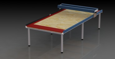
  1. upahill

    upahill New
    Builder

    Joined:
    Nov 3, 2014
    Messages:
    3
    Likes Received:
    1
    upahill published a new build:

    Currently working on Z-Axis
    [​IMG]

    Read more about this build...
     
    #1 upahill, Nov 5, 2014
    Last edited: Nov 5, 2014
  2. Tweakie

    Tweakie OpenBuilds Team
    Moderator

    Joined:
    Jan 18, 2014
    Messages:
    784
    Likes Received:
    326
    Very interesting design for a Z axis.
    At first sight it looks a little over complicated but it would certainly be rigid.

    Tweakie.
     
  3. upahill

    upahill New
    Builder

    Joined:
    Nov 3, 2014
    Messages:
    3
    Likes Received:
    1
    Over-complicated is my middle name. :)

    As I don't have any mech-eng experience, and the wife is likely to give me only one shot at building it I wanted to make sure it was sturdy enough for a lot of use. It will also be a good base to learn how to make some of the components I'm designing and gain some additional practical experience. I could use all standard off the shelf stuff but probably not as much fun.

    I also quite like the idea of the spindle being suspended between a double rail, with two sides for support, since the rail is 1.5m long I figured there might be a bit of movement so am looking at ways to beef it up. Since I can re-use most of the Openbuilds components, I may do it the OX way first, and use the machine to help build some of the parts for my design as an experiment. Making stuff like this will be fun and challenging (at least for me lol) ...

    [​IMG]

    006.JPG
     
    #3 upahill, Nov 6, 2014
    Last edited: Nov 6, 2014
  4. Florian Bauereisen

    Florian Bauereisen Well-Known
    Builder

    Joined:
    Feb 24, 2014
    Messages:
    188
    Likes Received:
    60
    Hi there,
    eventhough an intriguing design so far, i do not think this current z axis will lead anywhere.
    Linig up 4 rails will lead to more friction than neccesary and is tricky to set right to say the least.
    If you feel like building more sturdy use some heavy plates and linear rails to support. Sice 15mm (rails) beeing usually enough for hobbyists or if you feel like cutting aluminum 20mm rails .

    If you fancy a more sturdy machine you should not overlook the sideplates of your ox, cutting 3d pices will have your machine "wollbe" with accelleartions of your gantry , so a beefing up of the ox is likly to be disired.
    A simple L-shaped profile or even a square pipe would help tremendously.

    Also the spindle itself is not supportet at all in my opinion. it sits there beeing held only by the tiny clamp at the bottom?
    Just take a look at the comercial availible holders for hf spindles an you imideately see the difference:
    a massive clamp ( say 5 cm wide/or high however you decide to view it) around the spindle and screwed tightly to the supporting z-plate.
    If you think about a sturdy machine you should eliminate all possiblilities of any bending ( in your z-axis case it would rather be pivoting around your holder), once cutting forces beeing aplied.
    My seflmake clamps are beeing 3 cm and there sould be two of them -spaced some 5 cm apart along the spidle to give an example. Minimum clamp area of 30 cm/2 is mentioned in the instructions of my spinle.

    Just voicing my opinion.

    greets

    flo
     

    Attached Files:

  5. upahill

    upahill New
    Builder

    Joined:
    Nov 3, 2014
    Messages:
    3
    Likes Received:
    1
    Hi Flo,

    Thanks for the comments.
    I know what you mean about the spindle clamp, my original aim was to have 2 or three to hold the spindle, and probably a bit larger, the lower one shown so far was really just to support the chrome rails.

    The rod at the (rear?) would be a lead screw, and the remaining three clamps each have linear bearings in to help with alignment - I thought this might be enough, or at worse I would need to double up on them. As for the rest of the it I have a slightly more illustrative example of how I imagined it working, there is obviously still a lot of bits missing on it:

    Hopefully this vid works: https://upahill.tinytake.com/sf/MjMyN181MzUyMg

    However I see what you mean about the suggestions for beefing up a standard OX based system. I know nothing of the relevant forces so will gladly take any advice and am happy to ditch this design and do it differently if better.

    S.
     
  6. Florian Bauereisen

    Florian Bauereisen Well-Known
    Builder

    Joined:
    Feb 24, 2014
    Messages:
    188
    Likes Received:
    60
    As i said - intriguing design ...... but:
    There is hardly any support along Z .
    At least you should use six of your "bearings" and space them appart.
    In the pic of my machine you will notice two Hiwin linear bearings "on top of each other" (along Z-axis) to stop the "pivoting" i mentioned.
    This gives a supported length of aprox 14 cm. In your design you may have 3 points off attachement but i am sure the cutting forces would simply bend your spindle out of direction.
    By the time you have doubled up your bearings in Z you may as well go with a conventional design....

    Btw. propper linear bearings (using flat rails opposed to round "rods"/polished axles) screwed to a propper plate will give you a sturdy and easy to build/alingn setup- no wonder the industry uses them exclusively.

    greets

    flo
     

Share This Page

  1. This site uses cookies to help personalise content, tailor your experience and to keep you logged in if you register.
    By continuing to use this site, you are consenting to our use of cookies.
    Dismiss Notice