Welcome to Our Community

Some features disabled for guests. Register Today.

Super "C"-OX

Discussion in 'CNC Mills/Routers' started by anigeek65, Apr 20, 2016.
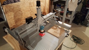
  1. anigeek65

    anigeek65 Well-Known
    Builder

    Joined:
    Sep 16, 2014
    Messages:
    57
    Likes Received:
    50
    anigeek65 published a new build:

    Read more about this build...
     
    Paul Stoller likes this.
  2. TerryOx

    TerryOx Well-Known
    Builder

    Joined:
    Apr 1, 2016
    Messages:
    90
    Likes Received:
    30
    That would be an impressive machine. Strong enough to give rides. :)
     
    #2 TerryOx, Apr 20, 2016
    Last edited: Apr 20, 2016
    anigeek65 likes this.
  3. thomas169

    thomas169 New
    Builder

    Joined:
    Apr 19, 2016
    Messages:
    2
    Likes Received:
    1
    Looks good! I'm planing something similar.
     
    anigeek65 likes this.
  4. Mark Carew

    Mark Carew OpenBuilds Team
    Staff Member Moderator Builder Resident Builder

    Joined:
    Jun 28, 2013
    Messages:
    2,741
    Likes Received:
    2,407
    Nice job on this Build @anigeek65 Sorry to hear you had a rough time cutting your plates, but glad to see you have them cut and are building from them. :thumbsup:
     
    anigeek65 likes this.
  5. anigeek65

    anigeek65 Well-Known
    Builder

    Joined:
    Sep 16, 2014
    Messages:
    57
    Likes Received:
    50
    It wasn't to much of a problem Mark. I would get through one plate fine and the second would walk. Played around with various feeds and speeds. I did notice much like wood grain that my piece of aluminum would make the cutter walk depending on its orientation. Kind of strange. But all in all it taught me alot, hence why I am making the z as strong as possible. This axis by far is the most sensitive of these types of hobby machine. I think the X and Y always seem to be fairly safe from the week zone. Thanks for following.
     
  6. Mark Carew

    Mark Carew OpenBuilds Team
    Staff Member Moderator Builder Resident Builder

    Joined:
    Jun 28, 2013
    Messages:
    2,741
    Likes Received:
    2,407
    Agreed it really is the heart of the machine. You may want to look at incorporating the new the C-Beam XLarge Gantry Plate it is the plate we are using on both the new larger C-Beam Machine and mill and it works great.
    That's what its all about :thumbsup:
     
    anigeek65 likes this.
  7. Barry Danks

    Barry Danks Well-Known
    Builder

    Joined:
    Apr 21, 2016
    Messages:
    113
    Likes Received:
    36
    I'm having issues with the spacing on the XL gantry plate I can spin the eccentrics 180 and the wheels barely touch the extrusion on 3 of 3 so far. I have contacted Mark and the team and waiting for response
     
  8. anigeek65

    anigeek65 Well-Known
    Builder

    Joined:
    Sep 16, 2014
    Messages:
    57
    Likes Received:
    50
    Are these plates you made or plates purchased from open builds? All the plates I have purchased were fine but the plates I made for this build none of the eccentrics worked. I had to go with eccentrics everywhere. You will have to drill out the holes for the 6mm spacers and replace with eccentrics. This is how others are solving this problem. I kind of like it that way anyway. It give me more flexibility and adjustability. Cost more but I like being able to adjust each wheel independently. Hope this helps. Oh sorry I see the XL gantry plate from open builds.
     
  9. Barry Danks

    Barry Danks Well-Known
    Builder

    Joined:
    Apr 21, 2016
    Messages:
    113
    Likes Received:
    36
    No I'm actually seeing the issue with the manufactured XL gantry plate I have 3 machines to build and am once again dead in the water
     
  10. anigeek65

    anigeek65 Well-Known
    Builder

    Joined:
    Sep 16, 2014
    Messages:
    57
    Likes Received:
    50
    Well I hope you figure it out. You could try my suggestion about the eccentrics everywhere but you could not return the plate. Maybe try one and see if this can solve you problem. Good luck.
     
  11. Evan F

    Evan F New
    Builder

    Joined:
    Oct 13, 2015
    Messages:
    44
    Likes Received:
    9
    Nice looking design! I like the spoil board support and the way you suspend the Y beams.

    Is the back to back C-Beam 100% necessary for the X beam? How stiff is a single C-Beam vs. 2 20x60 rails? I would worry about the long fasteners on the X/Z carriage spanning greater than 80mm flexing.

    I am working on a similar evolution for my 1000mm x 1000mm OX to eliminate X beam flex. I have been looking at the SMW3d R7 for inspiration. They are using a 800W spindle and claim it is stiff enough to cut aluminum. What do you think?
     
    anigeek65 likes this.
  12. anigeek65

    anigeek65 Well-Known
    Builder

    Joined:
    Sep 16, 2014
    Messages:
    57
    Likes Received:
    50
    Evan, thanks for the feedback. The back to back c-beam is incredibly strong. I tied the two c-beams together with several 2 hole joining strip plates. This plate is small enough that the v wheels pass by it, but tie the two beams together. It is much like having a I-beam and is very strong. I worry about the span of 1000mm for using 2 20x60 rails, plus I would not know how to keep them together and from separating in the center without the v wheels hitting something or from the rail twisting when pressure applied in the -y or +y. Also I now have a great place for the acme lead screw to run. I will eventually cover this with a bellows to keep chips out. As for the long fasteners, they don't seem to be a problem, I made provision for all my plates to add the mini v-wheels inside the c-beam rails if need be. I don't feel any flex or movement in them, but at the same time I have not cut aluminum with this. My biggest concern is the "Z" axis. That is the life blood of any machine and if not strong enough the end mill will chatter and grab and mess up the aluminum (much like the C-BEAM machine I used did to some of my parts. to solve this I will have a double plate on the z. It is not seen is this picture but I will have it done by then end of the week. As it is right now, when I grab the z axis at the spindle bracket I can hardly twist it. It will be even better after the second plate. The spoiler board is actually just my base to work on and support the wide foot print. I have 10 - 20x80 rails that I am going to lay down and bolt on and make a "T" slot bed. I have leftover 2"x2" angle I will cut and use for that. I probably wouldn't use that board as a spoiler board since it is laminated plywood and not very good for cutting on. I plan to eventually get a spindle and not the colt router I have.. but the budget is shot for now. Keep me up-to-date on you build. I will update this this weekend with the bed and new plate I hope. as you think more about your build if you have the $$ double plate your x, y, and z axis. Your machine will be much much stronger and this will also help keep the z axis from twisting when cutting aluminum. Which is the problem with the c-beam machine.
     
    #12 anigeek65, Jun 21, 2016
    Last edited: Jun 21, 2016
    Evan F likes this.
  13. Evan F

    Evan F New
    Builder

    Joined:
    Oct 13, 2015
    Messages:
    44
    Likes Received:
    9
    Thanks for the information. I may have to rethink my current plans...

    I look forward to seeing your bed and double Z-plate designs.
     
    anigeek65 likes this.
  14. jonathan lee

    Builder

    Joined:
    Aug 1, 2015
    Messages:
    6
    Likes Received:
    2
    Looks like the perfect cnc machine. I am planning on building my 1st cnc machine. Your design looks very good, can please you put up a parts list?
     
    anigeek65 likes this.
  15. anigeek65

    anigeek65 Well-Known
    Builder

    Joined:
    Sep 16, 2014
    Messages:
    57
    Likes Received:
    50
    I am still working the bugs out now. I was using an arduino board now I using the xpro and the new high torque nema 23 motor from the partstore. If I run at 2000mm/min the motors skip.. or I call it speed up and slow down. I am sure it's a setting somewhere. Once I get the bugs worked out I will upload a parts list. It's not perfect it is still not as strong as I would like but I believe that the extruded aluminum will never be strong enough for longer x travel.
     
  16. jonathan lee

    Builder

    Joined:
    Aug 1, 2015
    Messages:
    6
    Likes Received:
    2
    Ok thanks i reallly appreciate your help and support:)
     
    anigeek65 likes this.
  17. anigeek65

    anigeek65 Well-Known
    Builder

    Joined:
    Sep 16, 2014
    Messages:
    57
    Likes Received:
    50
    I have almost completed my build but have a question or need some input.
    Super "C"-OX
    I have lead screws that are 1000mm long on "X" and "Y, for the most part it runs pretty well but I have noticed that the bearings that I get from the parts store are not very accurate. I can move the screw up and down in the center hole meaning the hole ID is not very close the thread OD. when I travel I can hear clicking of the screw moving up and down in the bearing then the drive gets close to it.(not a deal breaker just annoying). I also have some whipping although not to terrible. My question is should I tear it down and reverse my plates so I can put the drive screws in tension instead of compression or just leave it alone and move on. (move the locking nuts to the outside.) I have seen others suggest this but I am not sure I want to do a complete tear down to accomplish this. Your thoughts...anyone? thanks in advance..
    What do you think Mark Carew?
     
  18. Rick 2.0

    Rick 2.0 OpenBuilds Team
    Staff Member Moderator Builder Resident Builder

    Joined:
    Dec 20, 2013
    Messages:
    2,852
    Likes Received:
    1,524
    If you are wanting to go with tension on the screws you should consider using thrust bearings. Also have you checked the size of the screws? The looseness may be due to an undersized screw not oversize bearings. And filling the gap is not that difficult but it will generally require disassembling the machine.
     
    Mark Carew and anigeek65 like this.
  19. anigeek65

    anigeek65 Well-Known
    Builder

    Joined:
    Sep 16, 2014
    Messages:
    57
    Likes Received:
    50
    Interesting Rick, how do you suggest filling the gap?
     
  20. Barry Danks

    Barry Danks Well-Known
    Builder

    Joined:
    Apr 21, 2016
    Messages:
    113
    Likes Received:
    36
    The TR 8 rod in general runs small, I have seen the same issue with my builds. The first TR rod you had to sand to get it to slip fit into the bearing which in my opinion was fine, but it also created an issue with the delrin nuts fitting to tight. I tension my Acme rods always have and always will. Tensioning the rod instead of compressing will also help with whip IMO.
     
    anigeek65 likes this.
  21. anigeek65

    anigeek65 Well-Known
    Builder

    Joined:
    Sep 16, 2014
    Messages:
    57
    Likes Received:
    50
    Thanks for the feedback Barry, since you build always in tension, does you notice a noise reduction also?
     
  22. Barry Danks

    Barry Danks Well-Known
    Builder

    Joined:
    Apr 21, 2016
    Messages:
    113
    Likes Received:
    36
    I guess I didn't notice that much noise I'll check into tonight. To make the TR lengths work I had to drill and tap 1 end M4 and use the standard lock collar at the other end
     
  23. anigeek65

    anigeek65 Well-Known
    Builder

    Joined:
    Sep 16, 2014
    Messages:
    57
    Likes Received:
    50
    I shouldn't have that problem, I have more than enough screw length to add lock washer at then ends on the outside.
     
  24. anigeek65

    anigeek65 Well-Known
    Builder

    Joined:
    Sep 16, 2014
    Messages:
    57
    Likes Received:
    50
    Thanks for the link, I just ordered a set...still processing whether I want to tear it down or not though..lol
     
  25. Rick 2.0

    Rick 2.0 OpenBuilds Team
    Staff Member Moderator Builder Resident Builder

    Joined:
    Dec 20, 2013
    Messages:
    2,852
    Likes Received:
    1,524
    I've been using epoxy based spray paint (appliance paint) on some bolts to get them filled out to fit the bearings on a project I've been working on. I spin them up in a drill to get an even coating and then let it set for a week. It comes out pretty hard, far harder than any forces that will be placed on it that would affect it. With a screw, JB Weld would also solve the problem but sanding it back to the right diameter may be a trick.
     
  26. anigeek65

    anigeek65 Well-Known
    Builder

    Joined:
    Sep 16, 2014
    Messages:
    57
    Likes Received:
    50
    Here is an update. I order the thrust bearings that Rick talked about but I don't have them yet. But I went ahead and moved the bearings I had to the outside on my z axis because it was the easiest and I wanted to try it. Boy what a difference. The noise level is nonexistent. Can't wait to do all the axis.
     
    Barry Danks likes this.
  27. snokid

    snokid Journeyman
    Builder

    Joined:
    Oct 11, 2014
    Messages:
    335
    Likes Received:
    104
    Looks like it will be a great machine.
     
  28. Brandoneous

    Builder

    Joined:
    Aug 17, 2016
    Messages:
    48
    Likes Received:
    4
    RE: the steel wheels,there is another CNC at my makerspace that's been around for a good while. It's got steel wheels riding on aluminum and those wheels have eaten right through the aluminum. If you do go steel wheels, I'd recommend steel to ride them on also...
     
  29. anigeek65

    anigeek65 Well-Known
    Builder

    Joined:
    Sep 16, 2014
    Messages:
    57
    Likes Received:
    50
    Agree...that is why I have not gone to steel wheels from the parts store. It works fine the way it is now. I am about to post my final results of this build in a few days to show the pros and cons and where I think that eccentrics fail in these style of designs.
     
  30. Jay Lytle

    Jay Lytle New
    Builder

    Joined:
    Dec 15, 2016
    Messages:
    80
    Likes Received:
    20
    Very nice build! Any chance you would have the drawing file for the plates? I would love to build a similar config. I had been working on solving the potential weakness of the X-Axis as well, and was trying to figure out exactly how to double up the C-Beam, but you showed me the answer I was slowly coming to.

    Thanks!
    Jay Lytle
     

Share This Page

  1. This site uses cookies to help personalise content, tailor your experience and to keep you logged in if you register.
    By continuing to use this site, you are consenting to our use of cookies.
    Dismiss Notice