Welcome to Our Community

Some features disabled for guests. Register Today.

OpenBuilds Promoveo Study Builds

Discussion in 'CNC Mills/Routers' started by Ronald van Arkel, Jul 6, 2016.

  1. Ronald van Arkel

    Staff Member Builder Resident Builder

    Joined:
    May 7, 2014
    Messages:
    472
    Likes Received:
    245
    GrayUK likes this.
  2. Rick 2.0

    Rick 2.0 OpenBuilds Team
    Staff Member Moderator Builder Resident Builder

    Joined:
    Dec 20, 2013
    Messages:
    2,892
    Likes Received:
    1,549
    You have finally mastered simplicity. :thumbsup::thumbsup::thumbsup:

    (Light years worth of growth since your first effort.)
     
  3. Moag

    Moag Veteran
    Staff Member Builder Resident Builder

    Joined:
    Mar 16, 2016
    Messages:
    183
    Likes Received:
    295
    Yep that's one sweet looking design Ronald. Have to agree with Rick, simplicity is a magical thing and you're got it. The strange thing is that there's nothing simple about simplicity other then it is just looks like the most obvious solution when seen. Great job. :thumbsup:
     
  4. ensari cokur

    Builder

    Joined:
    May 5, 2016
    Messages:
    29
    Likes Received:
    6
    Great design:) I wish I have waited for this one:) Already started to Routy 290 :)
     
  5. Ronald van Arkel

    Staff Member Builder Resident Builder

    Joined:
    May 7, 2014
    Messages:
    472
    Likes Received:
    245
    @Rick 2.0, what? The other one wasn't simple enough? :D

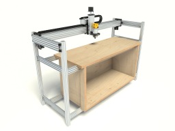
    Thank you, yes, this time I tried to use as much stock lengths as I could. The Routy BSX Gt2 290, 300, 310 were more based on using as less V-Slot possible and you had to cut every V-Slot used. You saw it; with the Promoveo series it's not needed to cut the parts (on the large machine you need too but that's not a beginner build). It's mostly due to the C-Beam used to it's full length and the stock V-Slot lengths that might be 2-3mm off. Fiddling around with the stock parts we have to get a whole machine takes a lot of time. I don't want to say it out loud but the design is an effort to replace the "ol' Ox", but, it's can't be replaced as it made a good impression on all of us, even loved by most of us (including me). Still, plates for the Ox can be hard to get in some countries and I hope that the Promoveo can help people to build their beefy CNC router without having to make their own plates first.

    @Moag, thank you, some one on the forum explained me the what KISS was, and I applied it fully with the small Promoveo. I saw that your C-Beam machine XL got a lot of feedback and you knocked yourself out with the special plates. Great looking machine too! :)

    @ensari cokur, thank you too. When you started to build the Routy 290 I had the Promoveo still in my head. It took me that long to finish the design you see here. Still, a lot of parts can be reused from the Routy build although I believe there is no shame in having a second CNC machine ;).

    ---

    More renders will be made today, my quad core isn't pulling it that fast when it comes to 2560x1920 pixel images...

    -Ronald
     
    Moag and eddiejr like this.
  6. Bad Sequel

    Bad Sequel Well-Known
    Builder

    Joined:
    Aug 19, 2015
    Messages:
    83
    Likes Received:
    32
  7. Ronald van Arkel

    Staff Member Builder Resident Builder

    Joined:
    May 7, 2014
    Messages:
    472
    Likes Received:
    245
    @Bad Sequel, thank you, I've a 1500mm model (1310mm cutting length) drawn as well. It might be an interesting model as you can slide a whole sheet in and cut it part by part. For sure a double belt and NEMA23 motors are recommended/needed :).

    -Ronald
     
  8. Bad Sequel

    Bad Sequel Well-Known
    Builder

    Joined:
    Aug 19, 2015
    Messages:
    83
    Likes Received:
    32
    @Ronald van Arkel That is interesting for sure.

    I have a 500mm X-carve sitting right next to me and the lack of workspace on it bothers me. It is fairly easy to extend the axis on the machine, but where is the fun in that?

    Building a new machine is much more fun! :thumbsup:

    Looking forward to further details.
     
  9. Ronald van Arkel

    Staff Member Builder Resident Builder

    Joined:
    May 7, 2014
    Messages:
    472
    Likes Received:
    245
    I've looked into the X-carve, but there are points that I don't like.

    To start with:
    - Seems the drag chain can't be opened and is a bit reduced so the router cable needs to be taped on the chain
    - Plates are not that sturdy, just powder coated 3.175mm / 1/8" steel sheet
    - 40x40mm rails
    - Not easy to create a double belt system (one belt glued into the V-Slot)

    Still, the metal X/Z-body is nice, and the belt tension is easy to adjust. The X-carve also has great out of the box software and is very easy to build. Also the price is good for the 500mm machine.

    However, there is no compare is sturdiness between the two, also not with the Shapeoko (those ones failed on the Z-Axis and the price... well...).

    ... I'm rendering the X/Z-body, will post them in a bit and :).

    -Ronald
     
  10. Ronald van Arkel

    Staff Member Builder Resident Builder

    Joined:
    May 7, 2014
    Messages:
    472
    Likes Received:
    245
    C-Beams added for the Y-axis, and some minor updates:

    Promoveo_2016_0_6_512.jpg Promoveo_2016_0_6_512_side.jpg Promoveo_2016_0_6_512_side_wheels.jpg Promoveo_2016_0_6_512_top.jpg Promoveo_2016_0_6_512_top_wheels.jpg

    @Moag, check out the picture above, 2 gantry plates, 4 wheels, no need for a 3rd plate ;).
     
    Moag likes this.
  11. Moag

    Moag Veteran
    Staff Member Builder Resident Builder

    Joined:
    Mar 16, 2016
    Messages:
    183
    Likes Received:
    295
    Wow, now that's combining thinking outside the box with "KISS", looking great mate.:thumbsup:
     
  12. MaryD

    MaryD OpenBuilds Team

    Joined:
    Apr 13, 2016
    Messages:
    649
    Likes Received:
    639
    Really like storage space underneath.
     
  13. Rick 2.0

    Rick 2.0 OpenBuilds Team
    Staff Member Moderator Builder Resident Builder

    Joined:
    Dec 20, 2013
    Messages:
    2,892
    Likes Received:
    1,549
    Ronald,

    How are you fitting eccentric spacers to the matching wheels on the bottom side?

    Eccentrics.JPG
     
    eddiejr likes this.
  14. Ronald van Arkel

    Staff Member Builder Resident Builder

    Joined:
    May 7, 2014
    Messages:
    472
    Likes Received:
    245
    @MaryD, thank you, the space might look small as the design doesn't use the whole width of the V-Slot supporting the box. It's designed with one complete sheet of plywood in mind as half a sheet isn't sold here. The 35-38kg plywood is supported by 4 V-Slot and 12 screws, but, to tell you the truth, I don't know how much weight the 4 beams can support without sagging. I can make a calculation but I'm sure it's over 100kg with wood included.

    @Rick 2.0, it was a bit tricky to add more wheels when just using 2 plates. There are 4 wheels on top and 3 wheels on the bottom. The bearings that are acting like pulleys are just 0.32/0.3mm distance from the wheels if the screws that hold everything together are centered, so, since I'm using 2x 1mm shims and 2x 5mm wide bearings, I´m going to swap the 4 parts out for 3x 4mm wide 105 bearings, the ones used for the mini V-Wheels, sandwiched in between 3x 1mm mini shims (8mm OD) and have the 9mm spacer swapped for a 6mm.

    This is how the setup looks from the bottom:

    upload_2016-7-10_11-17-16.png

    Mini bearings installed:
    upload_2016-7-10_11-33-45.png

    And some other details, on the Z-axis:
    upload_2016-7-10_11-36-0.png

    upload_2016-7-10_11-38-24.png

    So, one C-Beam end-plate ;).

    -Ronald
     
  15. Rick 2.0

    Rick 2.0 OpenBuilds Team
    Staff Member Moderator Builder Resident Builder

    Joined:
    Dec 20, 2013
    Messages:
    2,892
    Likes Received:
    1,549
    I'm really not sure the lack of bottom wheels out at the front face of the gantry beam is a good idea. While the top wheels will support the downward weight of the of the Z gantry there is nothing to prevent uplift other than bending of the extended spacers going to the back plate. And whenever a bit is trying to ramp downward into aluminum if there is not solid resistance to uplift there is reasonable probability the bit will just skip along the surface.
     
  16. Ronald van Arkel

    Staff Member Builder Resident Builder

    Joined:
    May 7, 2014
    Messages:
    472
    Likes Received:
    245
    I'm was skeptical about it as well, but I can tell you that the setup above is stronger than the original design of the C-Beam machine. Note that this is a test setup to see what the minimum amount of components are needed to get a strong build. Doubling up the plates is always better, we know this, and might be needed for aluminium cutting. Note that this machine is made for soft/medium-hard wood. Also the NEMA17 motors are relatively low power output, also there the test setup will show how far we can go.

    After this we can be sure and people can use this knowledge for their own design and/or builds so your comments are very welcome Rick :).
     
  17. Ronald van Arkel

    Staff Member Builder Resident Builder

    Joined:
    May 7, 2014
    Messages:
    472
    Likes Received:
    245
    The box is getting there. I went to a place where they sold sheets and had a sheet-saw (wall) as well, but, they forgot to adjust the saw before cutting the sheet and when I got back at my workshop I had the wonderful surprise of uneven cuts, not square, not the right size (up to 6mm off!) and had to my miter saw to cut things straight as I could, sure, loosing 3 to 6mm. Putting all together gave me a 1 to 2mm difference from one end to the other, diagonal, so I'm happy with the result. I used a lightweight plywood but would recommend to use heavier (more dense) plywood for a build.

    IMG_0986.JPG IMG_0987.JPG

    Screws will be removed, holed filled up, sanded and given a polyurethane finish next week. Tomorrow I'll start to build the mechanical part of the CNC router and will post the test results in the next days (mechanical part). Next week I hope to get 100nF capacitors and 10k resisters, shielded AWG18 cables and make a test setup to see what the digital DM556 do with the OpenBuilds NEMA17 71oz.inch motors :D. I might need to cool the motors as they will get 1.5A RMS @ 24vDC, that's a whopping 34 to 36W per coil ;).

    -Ronald
     
    Paul Stoller and GrayUK like this.
  18. Ronald van Arkel

    Staff Member Builder Resident Builder

    Joined:
    May 7, 2014
    Messages:
    472
    Likes Received:
    245
    Gantry put together:

    IMG_0119.JPG IMG_0120.JPG IMG_0121.JPG
     
    GrayUK likes this.
  19. Ronald van Arkel

    Staff Member Builder Resident Builder

    Joined:
    May 7, 2014
    Messages:
    472
    Likes Received:
    245
    Tomorrow is paint time, finally have time to work on it. I was busy with the DeWalt 611 and SketchUp:

    DW611_test4.jpg
     
    Josh B, Mark Carew, Kyo and 1 other person like this.
  20. Serge E.

    Serge E. Journeyman
    Builder

    Joined:
    May 6, 2014
    Messages:
    730
    Likes Received:
    252
    A really nice sharp looking setup, gives me a few ideas to rework myOX ...
     
  21. AlexHP

    AlexHP New
    Builder

    Joined:
    Jun 30, 2016
    Messages:
    12
    Likes Received:
    1
    Ronald, I am very impressed with your design. It caught my eye right off the bat. As a matter of fact, I am currently working on my first CNC design and am using your Promoveo as inspiration. Being an engineer, I just can't help but want to put my own spin on things. When I have my design finished I'll post some pictures.

    One question, though... Regarding the framework of the table, what benefit is there in using the extruded beams over wood beams (i.e. C-Beam is approx. a 2x4 profile)? Is there any better stability or operation or is it mostly for looks? The reason I ask is that using all those aluminum extrusions ends up being quite costly for what appears to amount to just a table, as opposed to building that in wood and then the actual machine using extrusions. I welcome your thoughts as well as anyone else's. Thank you.
     
  22. Bad Sequel

    Bad Sequel Well-Known
    Builder

    Joined:
    Aug 19, 2015
    Messages:
    83
    Likes Received:
    32
    What I like about this design is that both the machine and the "table" can grow together should the need to extend the Y axis become necessary. Minimal amount of wooden parts to redo.
     
  23. Bad Sequel

    Bad Sequel Well-Known
    Builder

    Joined:
    Aug 19, 2015
    Messages:
    83
    Likes Received:
    32
  24. Ronald van Arkel

    Staff Member Builder Resident Builder

    Joined:
    May 7, 2014
    Messages:
    472
    Likes Received:
    245
    Hello @Bad Sequel,

    Yesterday I put the base together but forgot to to take the camera with me. On Monday I hope to level the machine out but it's a pain since the box I build had badly cut wood parts and I have to play a little to get things straight; one corner of the box is 4mm off but only if you have an eye for it you would see it ;).

    I can tell you it's heavy and darn sturdy :D

    I've got to order shielded cables...

    -Ronald
     
  25. Ronald van Arkel

    Staff Member Builder Resident Builder

    Joined:
    May 7, 2014
    Messages:
    472
    Likes Received:
    245
    IMG_0099.JPG
    IMG_0098.JPG
    IMG_0097.JPG
    IMG_0096.JPG

    It's coming together well, easy to level the router with the bed. Now it needs the wasteboard (thinking about PVC or acrylic sheet) and the shielded cables. The electronics will be placed on the ceiling of the box, out of the way from dust but still easy accessible. Also, an E-Stop will be added and we are still looking to build the PID (RPM regulator). This setup uses a double belt drive, one belt is glued upside down into the C-Beam. Motors went from NEMA17 to NEMA23 so it can use stock GT3 pulleys.

    This is a test setup with just 2 stock XL C-Beam plates for the X / Z-body. This is done to reduce cost of the build and should be easier to build as well. The idea is to use as less parts as possible without having a weak machine. The Z-axis C-Beam with the 6 wheels has the most flex in it but it should not be a problem with a 1/8" bit and a not so deep plunge. The 1500mm C-Beam for the X-axis is as wide as you ever want to go, 1000mm might be an better option.

    In a few weeks we'll see how this CNC Router will perform!

    -Ronald
     
  26. Aussie58

    Aussie58 New
    Builder

    Joined:
    Aug 31, 2016
    Messages:
    10
    Likes Received:
    6
    Curious why you wouldn't go with lead screw gantry driving - I would have thought this length of belt drives might encourage a reduction in accuracy. Love the concept. By the way what shielded cables are you planning on using?
     
  27. SamKircher

    Builder

    Joined:
    Sep 12, 2016
    Messages:
    23
    Likes Received:
    12
    Loving this build! I think you have sold me on how I will do my build. So simple and effective!
     
  28. Aussie58

    Aussie58 New
    Builder

    Joined:
    Aug 31, 2016
    Messages:
    10
    Likes Received:
    6
    Ronald,
    thanks for the explanation and I guess I hadn't added up the overall length of 1340 which is quite long. I might stick with AWG18 shielded for my build only because there really is no price difference worth mentioning and it is easily accessible. My 'kit' for and XL should arrive in the next day or so. I am madly scrrening the forum for anything I can find to help reduce/eliminate and 'trip' hazards. Cheers and thanks. Bill
     
    gclayton and GrayUK like this.
  29. Ronald van Arkel

    Staff Member Builder Resident Builder

    Joined:
    May 7, 2014
    Messages:
    472
    Likes Received:
    245
    @SamKircher, I'll be uploading the sketchup file next week, doing some detailing to shave some USD of the build (might save a whole 5USD there ;) ). The drawing is for the 500mm C-Beam model that has "legs" of 250mm 40x40mm v-Slot screwed directly on the waste-board.

    @Aussie58, I just bought a 500' / 152m cable on eBay for 57.37USD + ~32USD shipping/customs, total of 90USD. Here in Mexico they wanted to see if I was stupid enough to pay 750USD for that spool! :blackeye:

    So, the build is on hold for a few weeks till the cables come in. This gives me some time to play a bit with EstlCAM and it's arduino uno "firmware"; Just cool stuff especially with the Mega 2560 support lately :thumbsup:.
     
    Aussie58 likes this.
  30. SamKircher

    Builder

    Joined:
    Sep 12, 2016
    Messages:
    23
    Likes Received:
    12
    Any updates on this Ronald? I'm sure I'm not the only one itching to see whats next!

    I have started designing my build, however I want to go to 1000mm X and maybe Y as well. (or the other way around), I would be very interested in having a look at the model for your larger design.

    I think this design could evolve into many iterations, possibly with lead screws? or a more expensive version that has more parts to make it stiffer?
     
    gclayton likes this.

Share This Page

  1. This site uses cookies to help personalise content, tailor your experience and to keep you logged in if you register.
    By continuing to use this site, you are consenting to our use of cookies.
    Dismiss Notice