Welcome to Our Community

Some features disabled for guests. Register Today.

Ooznest build - 1500mm x 1000mm

Discussion in 'CNC Mills/Routers' started by gavspav, Apr 2, 2016.
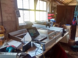
  1. gavspav

    gavspav New
    Builder

    Joined:
    Mar 22, 2016
    Messages:
    19
    Likes Received:
    6
    gavspav published a new build:

    Read more about this build...
     
  2. gavspav

    gavspav New
    Builder

    Joined:
    Mar 22, 2016
    Messages:
    19
    Likes Received:
    6
    So I've got the kit built up and am trying to get some action out of the stepper motors but nothing as yet!
    I have a 12v 30A power supply, an Arduino Uno, a CNC shield (protoneer clone) and 4 DRV8825 drivers driving Nema 23 steppers.
    I'm just hooking up one motor at a time and sending gcode from GBRL controller but I've tried direct from the Arduino Serial Monitor as well. The motors seem to be making a noise but I can't get them to move.

    I've got not jumpers so I'm not using any microstepping.
    The drivers aren't strictly powerful enough to run the motors at full torque and the 12v power probably isn't helping plus the lack of microstepping means the drivers are only putting out 60% power (I think).
    But would the combination of these things mean that the carriages don't slide even with no cutting/spindle?
    I'm guessing something should be happening really and I've made some other mistake.
    Any ideas?
     
  3. gavspav

    gavspav New
    Builder

    Joined:
    Mar 22, 2016
    Messages:
    19
    Likes Received:
    6
    Hmm. I took the belt off the x axis to take any tension off it and still can't get it to work.
    So that means its a gcode sender/Arduino/drv8825/power or motor issue.

    Edit. I wonder if I should try a different version of GBRL. 0.8 perhaps
     
    #3 gavspav, Apr 2, 2016
    Last edited: Apr 2, 2016
  4. Ryan Lock

    Ryan Lock Veteran
    Builder

    Joined:
    Oct 12, 2014
    Messages:
    530
    Likes Received:
    292
    Glad you got the machine built! It sounds like to me you have the wires from the motors connected in the wrong order to the controller. What is the colour order you have them in?

    Ryan
     
  5. gavspav

    gavspav New
    Builder

    Joined:
    Mar 22, 2016
    Messages:
    19
    Likes Received:
    6
    Yellow/Blue and Green/Red seem to be the coil pairs.
    Thats the order I've got them in.

    I flashed grbl 0.8 to my Uno today and the x axis worked straight off so I don't think it was the wiring!
    In my excitement I wired up the other 3 motors - now I can't get anything to work!
    Went back to my original set up of just the x axis with one driver in the shield and now that doesn't even work!
    Doh!

    I'm wondering if I've altered some gbrl setting or something. I'm going to reflash. Otherwise maybe I've fried something.
    Working just now aargh. So frustrating!!!

    Edit Checking the VREF of the stepper drivers they all give me big fat zero so I guess I must have fried the shield or the drivers. Or maybe its the thermal cut out. I'll try that first but I'm away for a week from tomorrow so I might order another shield or a different controller. Its ironic that the arduino part of the build is the bit tripping me up as that is the only area of which I have loads of experience!
     
    #5 gavspav, Apr 3, 2016
    Last edited: Apr 3, 2016
  6. Ryan Lock

    Ryan Lock Veteran
    Builder

    Joined:
    Oct 12, 2014
    Messages:
    530
    Likes Received:
    292
    That wire order is correct.

    Something is definitely up if Vref is giving zero on all axis.

    Ryan Lock
     
  7. gavspav

    gavspav New
    Builder

    Joined:
    Mar 22, 2016
    Messages:
    19
    Likes Received:
    6
    Back from Portugal now and received a new cnc shield whilst I was away.
    I tested each of the drivers in the x axis of the shield and using GBRL controller I could jog using any of the 5. So it seems like I fried the shield - the drivers still work.
    So I killed the power, loaded the shield with four drivcrs, connected the steppers and turned on the power again.
    The first jog of the x axis worked and then after that nothing - same as before - seems like the shield is dead again.
    Aargh frustrating - I wonder if I have definitely fried the shield or if it is some software setting.
    Maybe the y axes were fighting each other and drawing too much current or something? But wouldnt this kill the drivers?

    I realise now I should have tested each axis one by one after testing each shield but I think it might be too late.

    EDIT***Looks like its the fuse which is blown on my CNC shield. Don't know why. I've read people saying the fuse goes on these cheap clone boards and they've just bypassed the fuse by soldering a wire to it. Seems a bit sketchy to me. "Ah the fuse has gone. I'll bypass the fuse" but maybe I'll try it for now and then replace the fuse
     
    #7 gavspav, Apr 14, 2016
    Last edited: Apr 14, 2016
  8. gavspav

    gavspav New
    Builder

    Joined:
    Mar 22, 2016
    Messages:
    19
    Likes Received:
    6
    Ok so I bypassed the fuse with a thin part of the wire and moved my fire extinguisher and an old sweatshirt a bit closer.
    That got the steppers moving again. I tested each axis then inserted all the steppers and got all the axes working together.
    They all seem to make a similar noise so I'm hoping I've got it built up ok!
    I've ordered another shield but I'm guessing the fuse for that one will just blow straight away. Maybe not though - at least I definitely have the motors going in the right directions now.
    At least I can measure the resistance of the fuse before I blow it and work out what fuse to replace it with or something.
    I've got to go now but hope to upload some gcode tomorrow and see how it is performing. If it goes ok I'll go and buy a router and do some actual cutting!
     
  9. Ryan Lock

    Ryan Lock Veteran
    Builder

    Joined:
    Oct 12, 2014
    Messages:
    530
    Likes Received:
    292
    Thanks for update, sounds like your getting there. Some pics of your first cuts would be great!
     
  10. gavspav

    gavspav New
    Builder

    Joined:
    Mar 22, 2016
    Messages:
    19
    Likes Received:
    6
    Well, not got to the cutting stage yet but just doing some tests with a Sharpie attached to the router mount.

    I'm just using the jog arrows in grbl controller but I can tell something isn't right with the y axis. When I move in that direction there is a bit of a judder as if the machine is fighting with itself. You might be able to tell from looking at the attached picture - it doesn't look quite as bad in the image.

    So I need to check the y axis out. Belt tension, squareness of frame, wheel tightness. Is there any recommended order/procedure for going through these?

    If I hold one of the y carriages firm there is some play in the opposite carriage. Is this inevitable?

    EDIT**** I decided to start by testing each y carriage at a time. And one of them isn't working. Looks like the belt is slipping. It doesn't seem particularly loose so I slipped the belt off and I'm adjusting the spacers and seeing if I can free them off without introducing any play. Stay tuned folks (its ok I know there probably isn't anyone there!)
     

    Attached Files:

    #10 gavspav, Apr 15, 2016
    Last edited: Apr 15, 2016
  11. gavspav

    gavspav New
    Builder

    Joined:
    Mar 22, 2016
    Messages:
    19
    Likes Received:
    6
    Hmm bit stuck. Frame is square. I marked the pulley and the belt isn't slipping - the motor is just juddering and not moving the carriage.
    If I take the belt off the motor works fine so umm.
    Umm?
     
  12. gavspav

    gavspav New
    Builder

    Joined:
    Mar 22, 2016
    Messages:
    19
    Likes Received:
    6
    One of the wires had popped out of the terminal block.
    DOH!
     
    GrayUK and Chillimonster like this.
  13. GrayUK

    GrayUK Openbuilds Team Elder
    Staff Member Moderator Builder

    Joined:
    May 5, 2014
    Messages:
    1,668
    Likes Received:
    627
    Doh! Doh!Doh! Doh! LOL LOL At least you found the problem. :D
     
  14. gavspav

    gavspav New
    Builder

    Joined:
    Mar 22, 2016
    Messages:
    19
    Likes Received:
    6
    Slowly I edge towards the target......

    I spent a while getting the GBRL settings about right and then set about doing some drawing.
    Before I changed the step/mm settings the machine was making a healthy high pitched noise.
    When I changed them to accurately represent realtime measurements ie 1 virtual mm=1 mm the steppers started moving much slower, although probably the right speed for cutting, and the motors make a much more creaky noise.

    I thought I'd make a video in the hope that someone could tell me if this is 'normal'.

    I drew the Shapeoko hello world sketch. First time it started off ok and then the x axis stopped working - not sure why.
    I did it again and it worked pretty well although I think I put the pen a little low which meant it was pressing quite hard.
    The video is of the third attempt. There is a weird line across the O but I think this is just because the paper rose up a bit when the carriage was moving.

    If anyone has time I'd be grateful for a bit of feedback:
    VID_20160420_140745941-iPhone.m4v

    Any ideas for more tests I should do before cutting?
     
  15. gavspav

    gavspav New
    Builder

    Joined:
    Mar 22, 2016
    Messages:
    19
    Likes Received:
    6
    I've done a couple of cuts now and everything seems to be working.
    Probably need some fine tuning - not sure yet.
    I need to learn how to use it now!
     
    GrayUK likes this.
  16. gavspav

    gavspav New
    Builder

    Joined:
    Mar 22, 2016
    Messages:
    19
    Likes Received:
    6
    Here are a couple of cuts I've done with my machine just to test it out.
    Its a bit of a learning curve!
    I've been using a downcut 2 flute 8mm bit in my Dewalt D26200 which I have on medium speed.

    I think I have it set up right - measurements seem to be accurate and it goes back to where it starts and stuff.
    I'm just getting to grips with the software though and I make quite a few mistakes.
    I've been using Sketchup+SketchUcam and trying to use Inkscape but haven't managed to export any Gcode yet.
    Plus Grbl controller for the actual cuts.

    The things I'm finding difficult at the moment (if anyone can offer any advice!) are:

    - The lines in my software are narrower than the tool and so I get cut lines overlapping each other.
    - I can't work out how to specify z distance in sketchup and I'm not sure how to do several passes ie if I do one pass of 3mm I find it hard getting (guessing!) the second cut depth.
    - If you look at the z in the first image below - the bottom left of it is kind of wrong - this is the start and end point but they don't match up. I think this is a software or design issue as opposed to mechanical as it happens consistently/is reproducible.
    - I'm thinking maybe I should get a thinner cutting tool for this kind of work. But does that mean I need an insert or new collet for my router which has a 1/4" collet and only takes 6-8mm bits.
    - My belts seem to be getting loose. Any idea why?

    I'll obviously try to find the answer to these questions myself - but if anyone has any tips.....

    Thanks. And thanks Ryan for the kit. Think I'm getting there slowly!


    IMG_20160522_165829013_HDR.jpg IMG_20160522_165924044.jpg IMG_20160522_165846828_HDR.jpg
     
    GrayUK likes this.
  17. GrayUK

    GrayUK Openbuilds Team Elder
    Staff Member Moderator Builder

    Joined:
    May 5, 2014
    Messages:
    1,668
    Likes Received:
    627
    Ply is never a very good material to work with, and an 8mm bit is quite large in the scheme of things.
    Using a smaller bit allows for more repetitive actions and greater detailed work.
    A good thing when setting things up.
    Good start though.:thumbsup:
     
  18. gavspav

    gavspav New
    Builder

    Joined:
    Mar 22, 2016
    Messages:
    19
    Likes Received:
    6
    Actually it was a 1/4" bit (6.35mm) - I got confused.
     
  19. Ryan Lock

    Ryan Lock Veteran
    Builder

    Joined:
    Oct 12, 2014
    Messages:
    530
    Likes Received:
    292
    You should be able to get some cutters, with a 6.35mm shank, but 1/8" cutter.

    With the cuts overlapping, usually you will want some overlapping, how much is set by your stepover.

    To stop the belts from loosening, you may need to tighten the screw and nut holding them some more.

    Your z cuts not aligning may be also due to the issue with specify the z distance, i haven't really used sketchucam so can't offer much assistance there.
     
  20. gavspav

    gavspav New
    Builder

    Joined:
    Mar 22, 2016
    Messages:
    19
    Likes Received:
    6
    I've got a bit with an 1/8" cutter, plus I've tightened the belts up but I've notices some anomalies.
    Can anyone help me identify the cause?
    Firstly I've noticed that something is going wrong when I draw a circle. Straight Lines seem fine but in the examples below there is a fairly serious error - jumping a tooth or something? Seems to be when the x gantry is changing direction.
    circle2.jpg circle1.jpg

    The other issuse I discovered when trying to cut a box(below). This one could conceivably be software/human error I guess.
    I exported the gcode from Easel where I drew the boxes using an app, boxmaker.
    I'm using grbl controller. In the visualiser it looked like all the tabs should be the same size but when I cut them the ones along the x axis are all far bigger than the ones on the y axis (see the blue arrows) . Weird. All my distances seem ok. For example the circles above, for all their imperfections are basically the same width and height. Maybe its something to do with inside/outside lines? Or maybe another calibration issue.

    Of course I will be trying to suss out the causes of these issues but any pointers would be welcome! Thanks.


    box.jpg
     
  21. Ryan Lock

    Ryan Lock Veteran
    Builder

    Joined:
    Oct 12, 2014
    Messages:
    530
    Likes Received:
    292
    Your first issue to me looks like your pulleys are slipping on your motor shafts, so i would check they are tight, with one grub screw on the flat portion.

    The second issue i think is to do with the software
     
  22. gavspav

    gavspav New
    Builder

    Joined:
    Mar 22, 2016
    Messages:
    19
    Likes Received:
    6
    My first though was the pulley but I checked the grub screws and they seemed fine.
    On closer inspection there seems to be no slipping there. It is the actual shaft that is rocking.
    When I cut a circle and there is an error (intermittently) I can see that the shaft/pulley stop moving.

    I shall follow your advice (off thread) of swapping a couple of the motors.
    There is quite a bit of disassembly involved though I think? So before I will check the electrics and swap the drivers around - I'm using an arduino plus cnc shield.
     
  23. gavspav

    gavspav New
    Builder

    Joined:
    Mar 22, 2016
    Messages:
    19
    Likes Received:
    6
    No actually the pulley was slipping! When I took the belt off and checked again I spotted it.
    Thanks alot. Until next time!
     
    GrayUK likes this.
  24. Ryan Lock

    Ryan Lock Veteran
    Builder

    Joined:
    Oct 12, 2014
    Messages:
    530
    Likes Received:
    292
    Good to hear you got it sorted.
     
  25. gavspav

    gavspav New
    Builder

    Joined:
    Mar 22, 2016
    Messages:
    19
    Likes Received:
    6
    Back on the CNC mission after quite a long absence.
    I've made a reasonably effective dust shoe and I seem to be able to cut stuff without setting fire to anything.
    I've just resurfaced my spoilboard though and every pass has a little ridge on it which I guess is because the router isn't perfectly perpendicular to the cutting surface.
    This worried me slightly anyway as the position the router rests when the mount is tightened seems slightly arbitrary.
    Not that I'm doing anything critical at this stage.
    I attach a couple of images - a close up of the spoilboard and one of the router - I suspect I should also lower the mount a little.
    Is there any kind of procedure for checking the spindle angle?
    Thanks.

    PS Is this best asked in a new thread? Not really sure
     

    Attached Files:

  26. Ryan Lock

    Ryan Lock Veteran
    Builder

    Joined:
    Oct 12, 2014
    Messages:
    530
    Likes Received:
    292
    For your vacuum which you attach to the dust shoes, is that hose secured somewhere to offer strain relief, because if not i am thinking this could be the cause of your ridging issue.

    It is awkward to measure the angle because there is no flat surface on the router. I think the best way would be doing as you are by cutting a flat surface
     
  27. gavspav

    gavspav New
    Builder

    Joined:
    Mar 22, 2016
    Messages:
    19
    Likes Received:
    6
    Hmm I don't think it was the vac - I was using a combination of cable ties and holding it! Plus there is a bit of play in the dust shoe anyway.
    However I just took the router out to move the mount and one of the bolts is missing.
    I'm not sure if thats the cause - I did hold the z axis firmly and test to see if there the router would move - or if its just realigned but I think I might need a few spares. I'm going to email you now.
     
  28. gavspav

    gavspav New
    Builder

    Joined:
    Mar 22, 2016
    Messages:
    19
    Likes Received:
    6
    Another issue I've had is that I find it difficult to set the z axis home position ie when the bit is touching the material.
    I have been doing this either by eye or by turning the spindle on and listening to when it engages with the work.
    But I have noticed that there is often a bit of vertical movement in the work and/or spoilboard and this can make it hard to work out exactly how deep to cut. If I over compensate to make sure I cut through the work then it can mean there are no tabs which can lead to the job being ruined.
    I should probably secure the spoilboard better as well. Initially I just rested it on the supports but it was quite warped so I screwed it down to the bench at the corners and skimmed it.
    Thats not really good enough is it. Probably needs a bit more securing.
    Yup that's right I really don't know what I'm doing!
     
    Ryan Lock likes this.
  29. Giarc

    Giarc OpenBuilds Team
    Staff Member Moderator Builder Resident Builder

    Joined:
    Jan 24, 2015
    Messages:
    2,898
    Likes Received:
    1,613
    To zero the Z, I have found this method to be the best for me. This will only work if your Gcode is set so the spoilboard (tabletop in Sketchucam) is Z-zero. I always do it this way now. It's much easier and it cuts through the material but not into the spoil board:

    First, I put a bit in the collet further than it needs to be. Then, move the spindle to an area away from the workpiece and lower the Z until the bit is near the spoilboard. Then, loosen the collet and let the bit slowly slide down until it is stopped by the spoilboard. Next, tighten the collet and hit the "Z zero" button. Lift the z to a safe height and find your x and y zero. Now it will cut completely through the piece without damaging the spoilboard if it is properly faced. zzero.jpg
     
    #29 Giarc, Jan 13, 2017
    Last edited: Jan 13, 2017
    Ryan Lock, GrayUK and gavspav like this.

Share This Page

  1. This site uses cookies to help personalise content, tailor your experience and to keep you logged in if you register.
    By continuing to use this site, you are consenting to our use of cookies.
    Dismiss Notice