Welcome to Our Community

Some features disabled for guests. Register Today.

Moag's CNC Mill

Discussion in 'CNC Mills/Routers' started by Moag, May 9, 2016.
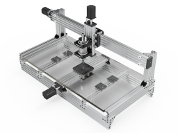
  1. Moag

    Moag Veteran
    Staff Member Builder Resident Builder

    Joined:
    Mar 16, 2016
    Messages:
    183
    Likes Received:
    294
    Moag published a new build:

    Read more about this build...
     
    Ronald van Arkel likes this.
  2. Rick 2.0

    Rick 2.0 OpenBuilds Team
    Staff Member Moderator Builder Resident Builder

    Joined:
    Dec 20, 2013
    Messages:
    2,852
    Likes Received:
    1,524
    Nice design. For your outrigger supports, you might consider the Mini V Gantry Plate™. This will give you a better thickness match to the center plate. They will also provide a flat surface to mount to. You will however need to add an extra precision shim at each wheel to achieve a true surface match with the center plate.
     
    silopolis likes this.
  3. Moag

    Moag Veteran
    Staff Member Builder Resident Builder

    Joined:
    Mar 16, 2016
    Messages:
    183
    Likes Received:
    294
    Thanks Rick, I was originally considering the 1/4" (6.35mm) Mini V Gantry Plate but didn't think of using an extra precision shim. Something to revisit in fusion 360. Got to like the design process, it's never ending, but I kind of like the challenge.
     
  4. Moag

    Moag Veteran
    Staff Member Builder Resident Builder

    Joined:
    Mar 16, 2016
    Messages:
    183
    Likes Received:
    294
    Outrigger_ASS_2016-May-10_03-10-54AM-000_RIGHT.png 1000x500mm MILL v10.png

    Much better solution for the "outriggers" Rick. I like it. So I'm still bit confused as to whether the plate is 1/4" (6.35mm) thick as here Mini V Gantry Plate™ or 6mm in the STEP Parts Library PDF. Not to really matter as I could make up the 0.35mm difference with some Tally-Ho cardboard between the Y beam and the frame:thumbsup:
     

    Attached Files:

  5. Rick 2.0

    Rick 2.0 OpenBuilds Team
    Staff Member Moderator Builder Resident Builder

    Joined:
    Dec 20, 2013
    Messages:
    2,852
    Likes Received:
    1,524
    I have a couple of older stock mini-V plates and they are 6.35mm. I'm not sure what the current stock is measuring but it would seem if both plate types are coming out of the same factory hopefully all the future plates will all have the same thickness just to bring a little more uniformity into the build process. (Ultimately, that's all up to Mark however.)
     
    Mark Carew likes this.
  6. Moag

    Moag Veteran
    Staff Member Builder Resident Builder

    Joined:
    Mar 16, 2016
    Messages:
    183
    Likes Received:
    294
    No worries Rick, I think I can work around it either way, though 6mm would be the preference.
     
    Mark Carew likes this.
  7. Moag

    Moag Veteran
    Staff Member Builder Resident Builder

    Joined:
    Mar 16, 2016
    Messages:
    183
    Likes Received:
    294
    As the saying goes, "measure twice cut once", I think I made a mistake. The measurement from the plate to the centre line of the Standard wheel assembly on paper is: 6mm spacer + 1mm precision shim + 5mm bearing + 0.5mm (1/2 precision shim) = 12.5mm. While for the mini wheel assembly it would be: 6mm spacer + 1mm precision shim + 1mm precision shim (mini wheel one) + 4.5mm bearing + 0.5mm (1/2 precision shim) = 13mm.

    So there would be a 0.5mm difference between the Standard wheel assembly and the Mini wheel assembly if you leave out or add a extra precision shim, before you take the plate thickness into consideration, by my calculations.

    Still not a problem with a bit of "Tally-Ho cardboard"; might just have to double it up though;)
     
  8. Rick 2.0

    Rick 2.0 OpenBuilds Team
    Staff Member Moderator Builder Resident Builder

    Joined:
    Dec 20, 2013
    Messages:
    2,852
    Likes Received:
    1,524
    Mini-V wheels use a 4mm bearing.
     
  9. Rick 2.0

    Rick 2.0 OpenBuilds Team
    Staff Member Moderator Builder Resident Builder

    Joined:
    Dec 20, 2013
    Messages:
    2,852
    Likes Received:
    1,524
    Also after seeing your tabulation it occurs to me the 0.35mm dimensional error can easily be resolved by swapping out the upper row of 6mm eccentrics and shims on the main plate with 1/4" shims and eccentrics.
     
  10. Moag

    Moag Veteran
    Staff Member Builder Resident Builder

    Joined:
    Mar 16, 2016
    Messages:
    183
    Likes Received:
    294
    Ah my bad, then it would all add up, just right. Thanks Rick:)
     
  11. GrayUK

    GrayUK Openbuilds Team Elder
    Staff Member Moderator Builder

    Joined:
    May 5, 2014
    Messages:
    1,668
    Likes Received:
    627
    Great design, and great renders! :thumbsup:
    Just a thought. :rolleyes: As per your design, are you able to use the full depth of your table?
    i.e. At maximum forward and back movement, are you able to align the cutter at pretty much both forward and rear leading edges, or would it be better to extend your out-riggers to allow for further, and more stable movement?
    Gray
     
  12. David the swarfer

    David the swarfer OpenBuilds Team
    Staff Member Moderator Builder Resident Builder

    Joined:
    Aug 6, 2013
    Messages:
    3,219
    Likes Received:
    1,813
    To my mind, the outriggers will never be as stiff as having 2 Y C-beams instead, with 2 Y motors. With a table that wide I feel it will twist when cutting near the left and right edges. Am I missing something?
     
    Joe Santarsiero likes this.
  13. Moag

    Moag Veteran
    Staff Member Builder Resident Builder

    Joined:
    Mar 16, 2016
    Messages:
    183
    Likes Received:
    294
    Cheers Gray. Cutting area forward and back from centre is about 155mm from memory before it hits the bump stops so 310mm safe work area in the Y-axis and around 720mm in the X-axis. The table will hang out 155mm out the front and back at full Y-axis movement. The centre point of the spindle is about a mm or so out, which is not too bad; so the spoil board won't be totally centred. The limiting factor is the Double Gantry plate assembly hitting the frame first followed the movement in the Y-activator. Yes, you could extend the outriggers to increase the stability, the mini V wheels will clear the frame mounting plates by design. Though it is something I'm not planning on doing, as I want to keep it to standard cut lengths of V-Slot if possible.
     
  14. Moag

    Moag Veteran
    Staff Member Builder Resident Builder

    Joined:
    Mar 16, 2016
    Messages:
    183
    Likes Received:
    294
    David that's one of my worries too. It's an experiment. If it doesn't work then not hard to add another one later.
     
    David the swarfer likes this.
  15. Moag

    Moag Veteran
    Staff Member Builder Resident Builder

    Joined:
    Mar 16, 2016
    Messages:
    183
    Likes Received:
    294
    This better? Design@2 v2.png :cool:
     
  16. Mark Carew

    Mark Carew OpenBuilds Team
    Staff Member Moderator Builder Resident Builder

    Joined:
    Jun 28, 2013
    Messages:
    2,741
    Likes Received:
    2,407
    Great looking design Moag! The only thing I would suggest is moving the Y motors to the back. Really nice work. You know we may need to bundle this one as the C-Beam Machine XL! ;)
     
  17. Moag

    Moag Veteran
    Staff Member Builder Resident Builder

    Joined:
    Mar 16, 2016
    Messages:
    183
    Likes Received:
    294
    Cheers Mark and please feel free to. :)
     
    Mark Carew likes this.
  18. GrayUK

    GrayUK Openbuilds Team Elder
    Staff Member Moderator Builder

    Joined:
    May 5, 2014
    Messages:
    1,668
    Likes Received:
    627
    Moag.
    The revised design is exactly how I plan to build my new CNC! :thumbsup::D
    Now you would have such good stability, maybe you could get a bit more travel by moving those stops on the X axis.
    Go for Max! :thumbsup:

    Mark.
    Like wise. You could save me a lot of calculating if you would be good enough to create an XL CBeam kit. :thumbsup::thumbsup:
    I plan to do as Moag has, and use two pieces of CBeam as the gantry support, so if you could supply a CBeam actuator, for my X axis, that is a meter, plus the thickness of 2 pieces of CBeam, I could then design a platen/table, nearer a meter wide. :)
    Please. Please. Please. Please. Please. Please. Please. Please. Please. Please. Please. Please. Please. Please. Please. :ROFL::ROFL::ROFL::ROFL:

    Gray
     
    Paul Stoller likes this.
  19. Mark Carew

    Mark Carew OpenBuilds Team
    Staff Member Moderator Builder Resident Builder

    Joined:
    Jun 28, 2013
    Messages:
    2,741
    Likes Received:
    2,407
    @Moag thank you sir :thumbsup:
    @GrayUK I have to agree with you as I have to say we could all use a XL version of the C-Beam Machine and now with the new XLarge Gantry Plates like Moag is using it seems the perfect fit.
    We will work up a bundle for this but in the meantime Moag has put together an awesome parts list (thank you) to help get one going now. This is going to be a nice machine to have and I look forward to building one soon.
     
    Paul Stoller and GrayUK like this.
  20. Moag

    Moag Veteran
    Staff Member Builder Resident Builder

    Joined:
    Mar 16, 2016
    Messages:
    183
    Likes Received:
    294
    Thanks gents, I'll have to work out a proper parts list and start saving my pennies as the Australian dollar is heading backward again, so might be a little while before I can make a start. Glad to be of some help in the meanwhile.
     
    GrayUK likes this.
  21. Moag

    Moag Veteran
    Staff Member Builder Resident Builder

    Joined:
    Mar 16, 2016
    Messages:
    183
    Likes Received:
    294
    Oh and your right Mark, it makes sense moving the Y motors to the back as it would certainly make the wiring more straight forward.
     
    Mark Carew likes this.
  22. Moag

    Moag Veteran
    Staff Member Builder Resident Builder

    Joined:
    Mar 16, 2016
    Messages:
    183
    Likes Received:
    294
    Ex_XZ-GantryPlateASS-Xlarge v6 v2.png Ex_XZ-GantryPlateASS-Xlarge v6 v3.png
    A bit of an idea to add some extra strength to the C-Beam I had a while ago. The plan is to add a 40mm x 20mm milled aluminium channel with a 2mm wall thickness tied into the C-Beam with T-nuts and 8mm low profile M5 screws.
    Being same size as the inside of the C-Beam some sanding of the channel would more then likely needed to fit and/or a stint in the freezer. My thought are that it would strengthen the C-Beam at its weakest points (circled in the cross section above).
    Another wacky thought is to fill the four hollows with Plaster of Paris to add extra weight rigidity to this design.

    Your thoughts.
     
    GrayUK likes this.
  23. Rick 2.0

    Rick 2.0 OpenBuilds Team
    Staff Member Moderator Builder Resident Builder

    Joined:
    Dec 20, 2013
    Messages:
    2,852
    Likes Received:
    1,524
    You might consider moving the nut blocks outward 1 row of holes as that's what those holes were designed for. The elongated openings allow for a slight adjustment such that two blocks can mesh on the same screw thread. The recess also allows for a 20mm screw to be used.

    Move Blocks.jpg
     
    Mark Carew likes this.
  24. Moag

    Moag Veteran
    Staff Member Builder Resident Builder

    Joined:
    Mar 16, 2016
    Messages:
    183
    Likes Received:
    294
    Yeap I know. You miss nothing. I was was just playing around with fitting two of the anti backlash nuts blocks with the ajustments to the outside.
     
  25. Paul Stoller

    Paul Stoller Journeyman
    Builder

    Joined:
    Feb 28, 2016
    Messages:
    157
    Likes Received:
    107
    I've been working on my own C-Beam (standard width for now, but I think it will be inevitable that I upgrade it at some point to double width), but one thing I've considered for a future build is to fill all of the extrusions with an epoxy granite mixture to add rigidity and deal with resonance.
     
  26. Moag

    Moag Veteran
    Staff Member Builder Resident Builder

    Joined:
    Mar 16, 2016
    Messages:
    183
    Likes Received:
    294
    Sounds interesting Paul, hope it works out well. Some kind of before and after assessment would be great, how to do that I have now idea at the moment. Looks like I will need to learn about epoxy granite mixture. The reason behind thinking of using plaster for me is it is something I'm familiar with using it for sculptures and mould making plus the obvious in that it is dirt cheap. One of the interesting properties with plaster is that it expands slightly when drying, about 0.03% from memory, so might produce a slight internal pressure which might just work. Next visit to the tip shop, looks like I will be looking for some junk aluminium tubing to experiment on and find a way to share the results of my crazy experiment.
     
  27. Paul Stoller

    Paul Stoller Journeyman
    Builder

    Joined:
    Feb 28, 2016
    Messages:
    157
    Likes Received:
    107
    That sounds interesting I may have to experiment with that as well, it certainly would be cheaper than epoxy. One thought is that you could probably add the same granite/sand aggregate that one would use with epoxy granite into the plaster.

    I had just come across epoxy granite when I was researching CNC machines in general. I had originally entertained the idea of trying to do an epoxy granite machine for my first build, but as I'm new to CNC I decided that i should get to learn the basics before I attempted something like that.

    Here is an example thread I had come across building a full machine out of epoxy granite.

    New Machine Build Large Epoxy Granite Vertical CNC Mill - Page 21

    And here is another where someone had use it to fill extrusions.

    http://www.cnczone.com/forums/attachment.php?attachmentid=30189&stc=1&thumb=1&d=1389508211

    http://www.cnczone.com/forums/attachment.php?attachmentid=129103&stc=1&thumb=1&d=1389524365
     
  28. Moag

    Moag Veteran
    Staff Member Builder Resident Builder

    Joined:
    Mar 16, 2016
    Messages:
    183
    Likes Received:
    294
  29. Paul Stoller

    Paul Stoller Journeyman
    Builder

    Joined:
    Feb 28, 2016
    Messages:
    157
    Likes Received:
    107
    That's a good link I had come across that one in my research as well.
     
  30. Moag

    Moag Veteran
    Staff Member Builder Resident Builder

    Joined:
    Mar 16, 2016
    Messages:
    183
    Likes Received:
    294
    I think you're on a winner there Paul, there's even a cookbook, sort of..
     

Share This Page

  1. This site uses cookies to help personalise content, tailor your experience and to keep you logged in if you register.
    By continuing to use this site, you are consenting to our use of cookies.
    Dismiss Notice