Welcome to Our Community

Some features disabled for guests. Register Today.

Mini-OX

Discussion in 'CNC Mills/Routers' started by James Gao, Mar 12, 2015.
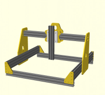
  1. James Gao

    James Gao New
    Builder

    Joined:
    Feb 21, 2015
    Messages:
    14
    Likes Received:
    25
    James Gao published a new build:

    Read more about this build...
     
  2. illconn

    illconn New
    Builder

    Joined:
    Dec 20, 2014
    Messages:
    3
    Likes Received:
    1
    I just recent cut some plates out of Acrylic(Extruded) and although they look great, they have a bit too much flex for me. I can move the gantry by hand(Y) hold one plate and move the other. I am going to re cut them with 3/8" cell cast this time and hopefully eliminate the flex or at least make it strong enough to cut some aluminum plates.

    Thank you for sharing the files, will keep an eye on this build :)
     
  3. James Gao

    James Gao New
    Builder

    Joined:
    Feb 21, 2015
    Messages:
    14
    Likes Received:
    25
    Thanks for the feedback! I was afraid of the acrylic plates flexing as well, so I have an alternate design that doubles the plates to further reduce flex. See the updated build. However, keep in mind that the Y-gantry is moved in step with a pair of motors, so the variety of flex you're talking about shouldn't affect the build quality.
     
  4. illconn

    illconn New
    Builder

    Joined:
    Dec 20, 2014
    Messages:
    3
    Likes Received:
    1
    Agreed, mid job I paused the calibration drawing and it did not flex much. let the drawing continue and flexed while moving and the lines were not straight but it did not throw the drawing off At the end.

    Not bad.
     
  5. illconn

    illconn New
    Builder

    Joined:
    Dec 20, 2014
    Messages:
    3
    Likes Received:
    1
    Also, I am really liking the Spindle.... I have some of those NTM motors and spare GT gears laying around. May have to give the spindle a go :)
     
    tore micaelsen likes this.
  6. Florian Bauereisen

    Florian Bauereisen Well-Known
    Builder

    Joined:
    Feb 24, 2014
    Messages:
    188
    Likes Received:
    60
    Hi,
    now that you have stiffend up the gantry sides your z-axis now is your weak spot.
    I would originally suggest to lower your z to the minimum you may think of ( pcp milling only needs a few mil), and change your z to something more stiff, but as you already did produce your side plates....
    In order to use what you have i would recomend to "raise" your bed as high as possible. Simply use stacks of mdf.
    Like that your milling motor will be close to the support rail and this hopefully enables you to mill your pcb´s with the desired acuracy ( less flex in z)

    Keep it up

    greets

    flo
     
  7. James Gao

    James Gao New
    Builder

    Joined:
    Feb 21, 2015
    Messages:
    14
    Likes Received:
    25
    I'm actually taking apart one of my existing 3D printers to put all the parts into the CNC mill. I'd like to retain the ability to 3D print by attaching my print heads to the Z axis-- this is why I left my Z axis so tall. I think my first project will be to mill 1/4" aluminium plates as an upgrade for this system. Thanks for your recommendation!
     
  8. Bertrand Roy

    Builder

    Joined:
    Jan 1, 2015
    Messages:
    14
    Likes Received:
    1
    HI,
    Very nice build. I've been following it for a bit. I'm curious to know what software you are using. Are on on Windows or Mac? I just built my OX and am at a complete loss to know what to use. I am on Mac. I have a Smoothie Board to control the CNC.
    Just to tell you home much of a newb I am, I don't even know how to do the pen test...
    Any help would be appreciated.
    Thanks.
    Bertrand
     
  9. BismarckDon

    Builder

    Joined:
    Aug 31, 2014
    Messages:
    12
    Likes Received:
    4
    Hi,
    I really like your machine design. I'm currently building a machine of my own. (Custom OX) I also have a MyDIYCNC Bigfoot machine that I started with. My plans are to disassemble this machine and upgrade it to either a smaller desktop CNC or a 3D printer. I was thinking of trying to mill gantry plates and connector plates from sheets of acrylic. Your spindle idea is awesome! Thanks for sharing.
     
  10. James Gao

    James Gao New
    Builder

    Joined:
    Feb 21, 2015
    Messages:
    14
    Likes Received:
    25
    I'm on linux. I've carried over a bunch of knowledge from building and running 3D printers, so this wasn't too bad. As for software, I'm using TinyG2 for the controller firmware. TinyG has an excellent interface, http://chilipeppr.com/ that lets you control the mill via a web interface. It requires some extra software to be installed on the computer, but it's pretty straightforward. It should work with Mac just the same.

    Unfortunately, I've never managed to play with any smoothie hardware yet -- they've generally been extremely expensive. The pattern is the same though -- you have the smoothieware firmware that actually runs the steppers, then your computer runs some software that sends out the Gcode line by line. This should work on mac: https://github.com/winder/Universal-G-Code-Sender
     
  11. James Gao

    James Gao New
    Builder

    Joined:
    Feb 21, 2015
    Messages:
    14
    Likes Received:
    25
    The acrylic plates are surprisingly pretty good. My plates are super tall, so there is a small amount of side-to-side drift. However, the belt stretch is much larger than the plate bend! My only complaint with the design is mostly the weak Z axis. The spindle can shift quite a lot in the +/- Y direction, because the wheels can't apply as much force in that direction. Hence why the aluminum plates will have the extra spindle mount plate!
     
  12. Daniel Dumitru

    Builder

    Joined:
    Aug 25, 2014
    Messages:
    1
    Likes Received:
    0
    Hi !
    Nice machine and heavy documented !
    Could you please share the design files ? I would like to modify it a bit. I mean to use only 20X40 profiles.
    I am thinking of a PCB making machine with a Dremel like tool.

    Kind regards,
    DAniel
     
  13. Ronald van Arkel

    Staff Member Builder Resident Builder

    Joined:
    May 7, 2014
    Messages:
    472
    Likes Received:
    245
    Hello Daniel,

    For the gantry you might look into a 40*40mm V-Slot instead of 2x 20*40 V-Slots; this will improve sturdiness and makes the build easier without breaking the bank.

    -Ronald
     
  14. Kaustubh Tripathi

    Builder

    Joined:
    Apr 9, 2016
    Messages:
    1
    Likes Received:
    0
    Really great build. I would like to make one to suit my needs. Can you please share the openscad files?
     
  15. lunknowl

    lunknowl New
    Builder

    Joined:
    Oct 26, 2016
    Messages:
    16
    Likes Received:
    1
    hi is this compatible with the 625zz bearing round
     
  16. lunknowl

    lunknowl New
    Builder

    Joined:
    Oct 26, 2016
    Messages:
    16
    Likes Received:
    1
    hi can i get the openscad file of this?
     
    crazerico likes this.
  17. eifelfloh

    eifelfloh New
    Builder

    Joined:
    Jan 31, 2019
    Messages:
    3
    Likes Received:
    1
    A really nice and clean build for millign small parts! Has anyone have the real frontplate? Cause fronplate and backplate X-Axis are the same...
     
    slow_bear likes this.
  18. slow_bear

    slow_bear New
    Builder

    Joined:
    Sep 5, 2020
    Messages:
    1
    Likes Received:
    0
    Is there any chance that we can have the 1:1 scale of the files in .pdf format? I do not have access to a milling / laser machine and I would like to cut them "by hand".
    Also the front plate and back plate are the same from what I could tell.
     
  19. JustinTime

    JustinTime Veteran
    Builder

    Joined:
    Dec 18, 2013
    Messages:
    755
    Likes Received:
    252
    Why don't you convert them yourself? Google how to print .dxf files 1:1 or how to convert them to .pdf
     
  20. eifelfloh

    eifelfloh New
    Builder

    Joined:
    Jan 31, 2019
    Messages:
    3
    Likes Received:
    1
    Ok...I´m not the greatest designer. But I´ve managed to draw two different front plates. Perhaps someone can take a look on this. The frontplate_test file was a scaled down frontplate from the OX design.
     

    Attached Files:

  21. Giarc

    Giarc OpenBuilds Team
    Staff Member Moderator Builder Resident Builder

    Joined:
    Jan 24, 2015
    Messages:
    2,892
    Likes Received:
    1,609
    Fusion 360 is free for hobbyists and can open the .dxf files. You can then print 1:1 drawings in the drawings section. Of course you will need the ability to print on larger sized paper (maybe), or you will have to split the part. There may be free online tools that can do this for you as JustinTime said. I often use this function to print parts before I cut them so I can see if they will fit properly, or I will email the PDF file to someone that asked me to cut the part for them so they can check it first before I cut the part for them.
    upload_2020-9-5_10-13-29.png
     
    #21 Giarc, Sep 5, 2020
    Last edited: Sep 5, 2020
  22. eifelfloh

    eifelfloh New
    Builder

    Joined:
    Jan 31, 2019
    Messages:
    3
    Likes Received:
    1
    Ok...the story continues.

    I´ve reworked the plates a little bit to fulfill my needs. At the moment I own a Shapeoko 2 without any updates so far.

    Because I´m not sure about milling aluminium and in the first step check if the design will work I´ve cut the first parts in multiplex birch (12mm).

    IMG_0096.JPG IMG_0097.JPG

    So far the parts fit right well. At the moment I need M5x80 screws :(
     

    Attached Files:

Share This Page

  1. This site uses cookies to help personalise content, tailor your experience and to keep you logged in if you register.
    By continuing to use this site, you are consenting to our use of cookies.
    Dismiss Notice