Welcome to Our Community

Some features disabled for guests. Register Today.

MakerSL MSL-8 OB Vise

Discussion in 'Other Builds' started by Sonny Lowe, Nov 2, 2016.
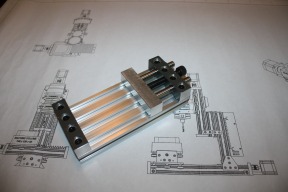
  1. Sonny Lowe

    Sonny Lowe Journeyman
    Staff Member Builder Resident Builder

    Joined:
    Nov 11, 2015
    Messages:
    143
    Likes Received:
    157
    Sonny Lowe published a new build:

    Read more about this build...
     
  2. Moag

    Moag Veteran
    Staff Member Builder Resident Builder

    Joined:
    Mar 16, 2016
    Messages:
    183
    Likes Received:
    294
    I want one so badly, fantastic:thumbsup:
     
    Sonny Lowe likes this.
  3. Sonny Lowe

    Sonny Lowe Journeyman
    Staff Member Builder Resident Builder

    Joined:
    Nov 11, 2015
    Messages:
    143
    Likes Received:
    157
    Thanks, it was a fun little build, and I think it will come in very handy :)
     
  4. Moag

    Moag Veteran
    Staff Member Builder Resident Builder

    Joined:
    Mar 16, 2016
    Messages:
    183
    Likes Received:
    294
    Totally, it's just one of those "so obvious designs" and yes very useful.
     
  5. Sonny Lowe

    Sonny Lowe Journeyman
    Staff Member Builder Resident Builder

    Joined:
    Nov 11, 2015
    Messages:
    143
    Likes Received:
    157
    Hey guys,

    Chris over on Google Plus asked me an interesting question...he wanted to know why I used 19mm square stock instead of 20mm and also wanted to know if 20mm stock would work.

    Short answer: YES, 20mm stock will work as long as you put all the holes on a 10mm center-line.

    Reasoning: Well, I initially designed the Vise using 20mm stock and 8mm pins. I changed those for two reasons, one, I'm in the US and we use the imperial system, so all our stock here at the shop is dimensioned as such, so 19mm was far closer to .750" than 20mm. I also used .375" for a similar reason, because I didn't have the proper metric tooling. I stuck with the M10 bolt because all the Milling Machine hardware is metric and I didn't want to add an odd ball wrench to the mix.

    Although this Vise is build-able with the information provided, I have done a couple additional things to make it is bit easier for everyone to understandable. I posted both metric and Imperial drawings (of the current Model). I have also made another CAD Model using all Metric hardware and stock with a Metric Drawing. I uploaded all the metric parts in .STP format.

    Hope this helps, and clears up any confusion I may have caused!?!?

    Sonny
     
    GrayUK likes this.
  6. Sonny Lowe

    Sonny Lowe Journeyman
    Staff Member Builder Resident Builder

    Joined:
    Nov 11, 2015
    Messages:
    143
    Likes Received:
    157
    This little vise seems to be morphing...which is a great thing :)

    Gino has come up with some additional Jaw ideas for his C-BEAM-GTC Machine, check out his BUILD as well as some amazing renderings of the Vise incorporated into his machining bed. I really liked his Jaw idea and expanded on it a bit, I added the jaw features via a set of Soft Jaws hat would bolt onto the Aluminum Jaws. This gives endless possibilities when it comes to Grooves, Slots, Ledges, Etc. here are a couple quick models showing two different sets of Soft Jaws. If anyone is interested I'll incoperate it into the overall design (as an option of course :cool:

    Soft Jaws.jpg Soft Jaws V-2.jpg


    Sonny
     
  7. Sonny Lowe

    Sonny Lowe Journeyman
    Staff Member Builder Resident Builder

    Joined:
    Nov 11, 2015
    Messages:
    143
    Likes Received:
    157
    I agree, and again that's the great thing about the removable jaws...easily adaptable :)
     
  8. GinoTheCop

    GinoTheCop Journeyman
    Builder

    Joined:
    Jan 28, 2016
    Messages:
    150
    Likes Received:
    196
    @JustinTime
    Something like this maybe? :rolleyes:

    [​IMG]
     
  9. Sonny Lowe

    Sonny Lowe Journeyman
    Staff Member Builder Resident Builder

    Joined:
    Nov 11, 2015
    Messages:
    143
    Likes Received:
    157
    Exactly...I like the second grove close to the bottom as well...might have add that too ;-)
     
  10. Rick 2.0

    Rick 2.0 OpenBuilds Team
    Staff Member Moderator Builder Resident Builder

    Joined:
    Dec 20, 2013
    Messages:
    2,852
    Likes Received:
    1,524
    Hopefully someday we'll get a more useful version of autocorrect, one that changes what the fingers are typing to what the brain was thinking. :)
     
    GinoTheCop, Sonny Lowe and Giarc like this.
  11. GinoTheCop

    GinoTheCop Journeyman
    Builder

    Joined:
    Jan 28, 2016
    Messages:
    150
    Likes Received:
    196
    Been playing with Fusion this evening and it has pretty good rendering as well..

    [​IMG]
     
  12. Rick 2.0

    Rick 2.0 OpenBuilds Team
    Staff Member Moderator Builder Resident Builder

    Joined:
    Dec 20, 2013
    Messages:
    2,852
    Likes Received:
    1,524
    Gino, very nice rendering :thumbsup:.

    Sonny, I needed a quick solution for doing some edge drilling and a play on your original design seemed the easiest approach. Just drop in the block, squeeze it together with a ratchet clamp and tighten the screws. The thin adhesive rubber pad on one side gives it all the grip needed.


    IMG_2402.JPG IMG_2405.JPG
     
    Mark Carew likes this.
  13. Sonny Lowe

    Sonny Lowe Journeyman
    Staff Member Builder Resident Builder

    Joined:
    Nov 11, 2015
    Messages:
    143
    Likes Received:
    157

    Rick,

    I love it, excellent example of how this little vise can be adapted and expanded for some many uses!!! I've cut a couple sample Soft Jaws, but still tweaking my CNC a bit so I'm not happy with the finish yet...hope to have a few real ones this weekend :)
     
  14. Sonny Lowe

    Sonny Lowe Journeyman
    Staff Member Builder Resident Builder

    Joined:
    Nov 11, 2015
    Messages:
    143
    Likes Received:
    157
    Darn it Gino, I can't get Fusion to do that LOL You are a rendering master :)
     
  15. Nick Bedi

    Nick Bedi New
    Builder

    Joined:
    Jun 6, 2017
    Messages:
    2
    Likes Received:
    1
    Do you have a place to purchase those strap clamps holding the vise to the table, or are those something to be machined yourself?

    Thanks so much for the design, Sonny!
     
  16. brandon d

    brandon d New
    Builder

    Joined:
    Jan 24, 2017
    Messages:
    1
    Likes Received:
    0
    Hi Sonny - could you point me to a part number of the component in the image attached?

    Thanks very much for this design. It's a great way to get started with workholding for first time CNC users.
     

    Attached Files:

  17. Michael Dwyer

    Builder

    Joined:
    Sep 26, 2017
    Messages:
    43
    Likes Received:
    10
    Sonny,
    Would you be willing to share the parts list? I just finished my MiniMill and I want to make a vise.

    Gino,
    Would you be willing to share the Fusion 360 file?
     
  18. Giarc

    Giarc OpenBuilds Team
    Staff Member Moderator Builder Resident Builder

    Joined:
    Jan 24, 2015
    Messages:
    2,892
    Likes Received:
    1,609
    The parts list is available in the parts list tab above. However, I noticed the link to the Onshape drawing is different than the finished product. It is a cool vise and I may make one, too.
     
  19. Michael Dwyer

    Builder

    Joined:
    Sep 26, 2017
    Messages:
    43
    Likes Received:
    10
    Thanks! I just learned something new about these forums - I should look at the top menu to see if there is a parts list.
     
  20. AndyC

    AndyC New
    Builder

    Joined:
    Feb 13, 2016
    Messages:
    13
    Likes Received:
    7
    IMG_20171208_211143177.jpg What a nice design. Thanks! I built one today. Works very nice, with the caveat below:

    I made a couple of mods:
    1) tapped the 3/8" OD dowel pins for M5. Put countersunk clearance holes for M5 screws in the slide block opposite the holes for the dowel pins, and put screws through the block into the dowel pins to hold them in. I could have press fit the pins in, but runout in the bridgeport I used made the holes too loose.
    2) Like the discussion above, I also put M5 tapped holes in the stop block (same location as the screws into the slide block). This will allow for attaching replaceable jaws on both blocks, much like shown in the discussion above.

    I found a problem in the Parts List. The specified M10 bolt (91290A220), is a standard 1.50mm pitch screw. The specified Helicoil (91732A809) is a fine thread, 1.25mm pitch. I did not check this carefully before building, ARGH (head-smacking bench sound)! The correct Helicoil is McMaster 91732A800. I did find hex-head bolts with 1.25mm ptich, so I dont have to remake the part; note that fine pitch M10's are uncommon - better to stick with 1.50mm pitch.
     
  21. Michael Dwyer

    Builder

    Joined:
    Sep 26, 2017
    Messages:
    43
    Likes Received:
    10
    Sonny,

    In the photos, your vise appears to be mounted directly on the x-axis gantry plate of the MiniMill. On my MiniMill, the top of the gantry plate actually sits below the top of the C-beam end plates. How is the 80x20 v-slot base clearing the tops of the C-beam end plates?
     
  22. Rick 2.0

    Rick 2.0 OpenBuilds Team
    Staff Member Moderator Builder Resident Builder

    Joined:
    Dec 20, 2013
    Messages:
    2,852
    Likes Received:
    1,524
    A 1/8" shim will raise it enough to clear the end plates.
     
  23. Sonny Lowe

    Sonny Lowe Journeyman
    Staff Member Builder Resident Builder

    Joined:
    Nov 11, 2015
    Messages:
    143
    Likes Received:
    157

    Thanks, I'll update the BOM as soon as I get chance.
     
  24. Sonny Lowe

    Sonny Lowe Journeyman
    Staff Member Builder Resident Builder

    Joined:
    Nov 11, 2015
    Messages:
    143
    Likes Received:
    157
    Rick nailed it, I actually use a piece of Teflon bolted to the gantry plate and when skimmed to make sure it's flat.
     
  25. Sonny Lowe

    Sonny Lowe Journeyman
    Staff Member Builder Resident Builder

    Joined:
    Nov 11, 2015
    Messages:
    143
    Likes Received:
    157
    So sorry for the late reply to this, it's been a long few months :-o

    That is a CAD file, it is meant to be machined so there is no part number. I'll try to locate the file and post it in case you want to give it whirl ;-)
     
  26. Michael Dwyer

    Builder

    Joined:
    Sep 26, 2017
    Messages:
    43
    Likes Received:
    10
    That is what I assumed, but I could not see a shim in the photos.
     
  27. Peter Grace

    Builder

    Joined:
    Nov 19, 2016
    Messages:
    2
    Likes Received:
    2
    Hi all,

    Figured I'd post a video of my minimill facing the sides of the msl-8 vise.

    Thank you Sonny for this design, I was perplexed how I was going to do work holding on the MiniMill.

     
    Sonny Lowe and GrayUK like this.
  28. Sonny Lowe

    Sonny Lowe Journeyman
    Staff Member Builder Resident Builder

    Joined:
    Nov 11, 2015
    Messages:
    143
    Likes Received:
    157

    Peter,

    Thanks for sharing your video, it makes me smile every time I see someone using the their MiniMill to make tools for their MiniMill :)

    Glad you like the design and I hope it works out well for you!!

    Sonny
     
    Peter Grace likes this.
  29. Michael Dwyer

    Builder

    Joined:
    Sep 26, 2017
    Messages:
    43
    Likes Received:
    10
    Sonny,
    Using my MiniMill to make tools for my MiniMill hasn't gone so well for me yet. Three attempts at milling the fixed block have been failures. It's challenging finding a way to hold material I'm milling to hold material. I've also had various glitches maintaining work coordinates when switching to a different operation using a different bit. By my second attempt, I had a sure fire way to hold the material, successfully bore/counter-bore the screw holes and face off the top of the material. Where I'm having the most problems is milling the sides of the blocks. I thought it would be a good idea to face the top, bore the holes and mill (contour) the sides all without removing the material from my makeshift clamp/vise to make sure the top and sides are perpendicular to one another. By doing that, I felt I could turn over the material and know it would sit square in my clamp/vise for facing off the bottom. Unforunately, the contouring operation for the sides has not gone well. The main problems been preventing the material from moving and getting a smooth finish. I think I have a better idea to keep the material from moving, but I'm wondering about how to get a smooth finish.

    Could you explain your operations in milling the individual pieces of the vise so I can compare. Could you also let me know what kind of bit, feeds and speeds you are using for each operation?
     
  30. Sonny Lowe

    Sonny Lowe Journeyman
    Staff Member Builder Resident Builder

    Joined:
    Nov 11, 2015
    Messages:
    143
    Likes Received:
    157

    Michael,

    Sorry but I'm not help on this one. Although I've made a ton of tooling on my MiniMill I made my vise on a conventional milling machine.

    Hopefully someone that actually milled their Vise using the MiniMill will chime in.

    Regards,
    Sonny
     

Share This Page

  1. This site uses cookies to help personalise content, tailor your experience and to keep you logged in if you register.
    By continuing to use this site, you are consenting to our use of cookies.
    Dismiss Notice