Welcome to Our Community

Some features disabled for guests. Register Today.

LS-LASER

Discussion in 'Laser Cutters' started by LukasK, Jun 26, 2018.
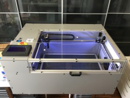
  1. LukasK

    LukasK New
    Builder

    Joined:
    Feb 25, 2016
    Messages:
    21
    Likes Received:
    38
    LukasK published a new build:

    Read more about this build...
     
  2. neo__04

    neo__04 New
    Builder

    Joined:
    Dec 2, 2017
    Messages:
    5
    Likes Received:
    0
    Hey,

    Wondering what your actual work/cut area is?
     
  3. LukasK

    LukasK New
    Builder

    Joined:
    Feb 25, 2016
    Messages:
    21
    Likes Received:
    38
    On my actual setup it is 590x400mm and 140mm on Z axis travel. You would be able to add aprox. 25 mm on X and Y axis if you leave out max endstops. Anyway it should be no problem to enlarge, the construction seems pretty rigid and adding 200-300 in each direction should work.
     
  4. neo__04

    neo__04 New
    Builder

    Joined:
    Dec 2, 2017
    Messages:
    5
    Likes Received:
    0
    Thanks for that. Your build looks awesome. Just trying to clarify a few details, You are running linear rails fixed to extrusion? (what size?) Just drilled and tapped?
     
  5. LukasK

    LukasK New
    Builder

    Joined:
    Feb 25, 2016
    Messages:
    21
    Likes Received:
    38
    Thanks:) You are correct, those linear rails are fixed directly to v-slot extrusion. Those are MGN12 linear rails fitted with MGN12H sliding blocks. There is no need to drill or tap anything, rails are already predrilled. Just slide in M3 nut blocks into extrusion and fasten rails to them with M3x8 (maybe M3x6 can remember now) socket cap bolts and rails will sit nicely on 2020 v-slot extrusions. The X axis is the same principle however the 2020 extrusion is attached to Y MGN sliding blocks using 3D printed fixture.
     
  6. LukasK

    LukasK New
    Builder

    Joined:
    Feb 25, 2016
    Messages:
    21
    Likes Received:
    38
    This photo is actually from 3D delta printer I have at home as the laser cutter is located in my “dirty” workshop. Nevertheless it shows nicely how is the rail attached to, in this case 2040, v-slot extrusion.

    758F6AF6-FEDA-44EB-B6AF-5026402713A1.jpeg
     
  7. johanndp

    johanndp New
    Builder

    Joined:
    Jan 13, 2017
    Messages:
    3
    Likes Received:
    0
    Really neat and nice built for sure. well done on your success.

    Do you have drawings on the electronics and wiring. I've built A hobby CNC, similar to the X-carve and are busy designing a much stronger machine to cut aluminium. I've also got two 3D printers and the obvious next step will be a laser cutter/engraver. I've got the basics sorted but now need to figure which controllers and electronics to get. The mechanical side is fine and easy for me but I'm struggling with the electronic side. which controllers, breakout, …. did you use? do you have a PC connected to the laser permanently or is there a way to have it running on it's own? GBRL or Mach3? I want to use the same foundation of control on my new CNC.

    your comments please.

    Johann
     
  8. LukasK

    LukasK New
    Builder

    Joined:
    Feb 25, 2016
    Messages:
    21
    Likes Received:
    38
    I have wired the electronics “on the go” so I don’t have any schematics. Anyway I can try to show you the direction. The controller itself is MKS Sbase v1.3 (I’ve donated original Smoothieware) which some kind of clone of Smoothieboard and it is running cnc version of Smoothieware. This combination satisfies my needs - 32bit, USB connection, highly configurable output pins.

    As I have used a lot of stepper motors 17HS19-2004S1 I also used external stepper drivers DM320T. To see how to connect them as open drain you can refer to general-appendixes [Smoothieware]. What took me some time was wiring drivers for Z axis. I had one driver for each of four motors and the logic from controller was connected to each of them in parallel. The problem was that MKS board didn’t provide enough current to run 4 drivers (as a result, the motors run at different speed). Solutions I can think of are two : use one driver for two motors or use some non-inverting CMOS buffer. I have used the first option, was easier one and the driver provides enough current to supply two motors.
    Controller is using 3V logic which fine for all applications in this cutter except one - laser pwm control. The chinese high voltage power supply I have (and mostly all other will) expects 5V for laser power control - bluebox-guide [Smoothieware]. This you achieve by using any kind of level shifter. All the other connections and switch configuration for fans, pump etc. you easily find on Smoothie’s website.

    To have the machine running even without my Mac it is fitted with Raspberry Pi. This RPi connects to MKS usb port, it connects to 7” touchscreen and has the rest of usb ports extended to top panel. I control it either via touchscreen or wireless keyboard. On the RPi Raspbian is installed, it creates it’s own hotspot and runs AFP service so you can upload gcode files. For the control itself I have installed bCNC, LaserWeb4 and Pronterface console and I run whatever suits my current needs the best.
     
  9. johanndp

    johanndp New
    Builder

    Joined:
    Jan 13, 2017
    Messages:
    3
    Likes Received:
    0
    thank you very much for the advise, I've got some reading and research to do.
     
  10. LukasK

    LukasK New
    Builder

    Joined:
    Feb 25, 2016
    Messages:
    21
    Likes Received:
    38
    Finally got home so I can upload some more stuff that may help you in your research.

    When you search for cheap high voltage PSU you most likely find those "blue" on eBay or Ali. Useful pinout with description below. Compare it with my photos to get better insight.
    high_voltage_psu_pinout.png high_voltage_psu_description.png IMG_5754_small.jpg IMG_5739.JPG IMG_5742.JPG

    Maybe the Smoothieware config file I'm running on my setup itself will help you as well. Attached as .txt however on card it has to be placed without extension.

    There are a lot of MKS pinout pictures all over the internet however most of them have one pin labelled incorrectly, that caused me a lot of headaches why it is not working as expected.
    mks_pinout_corrected.jpg
     

    Attached Files:

  11. johanndp

    johanndp New
    Builder

    Joined:
    Jan 13, 2017
    Messages:
    3
    Likes Received:
    0

    Thank you very much. I'm planning to start in about 3 months time. will keep you posted.
     
  12. Wiseer

    Wiseer New
    Builder

    Joined:
    May 12, 2018
    Messages:
    8
    Likes Received:
    0
    I really like your work, you are doing a great job.:thumbsup:
    I am not very good at structural design, such as the fixing of the motor, the fixing of the screw, and the frame design of the entire platform, beautiful and concise, I really admire you, I hope to learn more interesting knowledge from you, if you want, would I get a specific list of your platform construction? thank you very much!:)
     
  13. elahd

    elahd New
    Builder

    Joined:
    Jan 7, 2016
    Messages:
    1
    Likes Received:
    0
    What was your approximate build cost?
     
  14. LukasK

    LukasK New
    Builder

    Joined:
    Feb 25, 2016
    Messages:
    21
    Likes Received:
    38
    Many thanks:) Today I have made some "serious" cutting of 5mm PVC and I must say I'm more than happy. Very nice, straight and clean cut with 101.6mm lens (I have another laser head lower part with 50.8mm lens for engraving).

    All motors are NEMA17 size and they are fixed using standard bracket. Only X axis motor is mounted using OpenBuilds motor mount plate. Lead screws are 300mm TR8 fixed using KP08 pillow block.

    The frame is build from different v-slot extrusions lengths as specified in attached SketchUp file. They are attached to each other using 2020 corners, m5 slide-in nut blocks and M5 low profile screws. Nearly every corner has those 2020 corner brackets.

    No detailed part list exists for this build and I actually don't plan to put one together. I have tried to take photos so they show most important parts of the construction, if you would like to know anything specific just ask:)
     

    Attached Files:

  15. LukasK

    LukasK New
    Builder

    Joined:
    Feb 25, 2016
    Messages:
    21
    Likes Received:
    38
    Well this is a question I have never wanted to ask myself;) I made some mistakes, some of the materials such as connectors, wires, screws etc. you can't buy at exactly the amount/length you want so some will be left. A qualified guess is somewhere around $2.5k:duh:
     
  16. Wiseer

    Wiseer New
    Builder

    Joined:
    May 12, 2018
    Messages:
    8
    Likes Received:
    0
    Thank you for your prompt reply;).
    I would like to first understand the dimensions associated with the slide rails and how the fixed rails are connected. Are you using two motors to drive the left and right movement of the contact? How can I ensure the synchronous operation of the two motors? Looking forward to your reply!
     
  17. LukasK

    LukasK New
    Builder

    Joined:
    Feb 25, 2016
    Messages:
    21
    Likes Received:
    38
    If you open up the SketchUp file and locate the extrusions where the linear rails are attached you will get the dimenssion. Actually I have shortened them slightly to fit some stops on each end because the linear blocks are very easy to slide off during construction or misuse during operation. On below photo you can see last attaching screw is much larger than it should be, that is instead of those stops which were fitted later.

    IMG_4828.JPG

    Read the thread posts #5 and #6 to learn about fixing those rails to extrusions. The X axis extrusion is attached to those MGN blocks using own design 3D printed part.

    IMG_5734.JPG X_Y_CARRIAGE v16.png

    Each side has its own stepper motor controlled through own stepper driver. Right side motor and its attachment :

    IMG_5744.JPG

    Those drives however share the same input from controller so they operate in sync. Those axis are pretty light and powered by 1.8A per coil so no worry about missed steps. Top left 2 drivers are for Y axis wired in parallel, the right most 4 drivers the same use case but for Z axis motors.

    IMG_5717.JPG
     
  18. Wiseer

    Wiseer New
    Builder

    Joined:
    May 12, 2018
    Messages:
    8
    Likes Received:
    0
    You are so enthusiastic. Your answer is very detailed, I have clearly understood the above questions. With your patience, I have more confidence in this project. I hope that by learning this machine, I will make a 3D printer myself. Its structure should be similar to the makerbot, and XYZ will adopt a closed loop. I will also use the line rail to do the X and Y axis translation, and use the screw to do the Z axis up and down movement. I even built a platform according to your mechanical structure, and then implemented it with the main control board of the 3D printer. The location of the power supply and the location of the display will be learned from you, but I hope to have my own characteristics. It has to be said that the angle of your picture is very good, always able to clearly reflect the specific content of the machine, just as beautiful as your machine.
    I hope that there will be more exchanges in the later period. If I have too many questions, it is not because you are not clear enough. It must be that I am too stupid. Please forgive me:p.
     
  19. Wiseer

    Wiseer New
    Builder

    Joined:
    May 12, 2018
    Messages:
    8
    Likes Received:
    0
    I still have some questions about the wires. I see that the wires you use are very suitable. What are the names of these wires? Where can I buy a good quality wire? Your machine circuit layout is very neat, do you have any good experience with machine wiring? Looking forward to your reply!
     
  20. LukasK

    LukasK New
    Builder

    Joined:
    Feb 25, 2016
    Messages:
    21
    Likes Received:
    38
    I tried to take photos of key elements during the build time. Now when the build is finished it would be difficult and for some parts even impossible without disassembly. So I have to suffice with pics that have been already taken:)

    I could not recall Makerbot conception so I took a look. Do you already have some 3D printer? Somewhere at the biginning you have stated that you struggle a little bit with mechanics. If I would be on your place, I would consider some other conception to start with. Something that is open source, something with wide user base. Than I would do some community or personal upgrades, only after that I would start to build something with "own design". I have built several machines for past years and I can imagine that if you're just beginning with such projects it could be pretty steep learning curve. This laser cutter is mine fifth machine in row and second which I designed myself (with some inspiration of course) I can honestly say it was the hardest nut to crack. I don't know your skills and knowledge so please don't take this bad or as any kind of discourage from doing what you dream of! Just a thought..
     
  21. LukasK

    LukasK New
    Builder

    Joined:
    Feb 25, 2016
    Messages:
    21
    Likes Received:
    38
    For all the wiring I have used different diameter of soft silicone wires. For motors it was I suppose 22AWG and for logic control 28AWG, for wires from PSUs of course thicker. I admit that silicone wires are a little bit overkill and pricey, I just like them.. All the wire bundles are put into PET wire mesh (guess 4 and 6mm) with ends secured by shrink tube. Most parts including wires were purchased on AliExpress.
     
    Wiseer likes this.
  22. Wiseer

    Wiseer New
    Builder

    Joined:
    May 12, 2018
    Messages:
    8
    Likes Received:
    0
    I have just graduated from college and want more practice to improve my professionalism. I know this process is very difficult, just like you said. Your advice is very sincere, thank you for sharing.:)

    I don't have a 3D printer, I have research in this area before. I think you might be confused, I am not the one that struggle a little bit with mechanics.My university major is mechanical design and automation, just graduated in June this year.

    I have previously worked on Writing and Drawing Machines, which is similar to the AxiDraw made by the Evil Mad Scientist team. I also use the core xy structure, using 3D prints to group frames. Do you know this machine? In this machine production, I learned a lot about control and opened up my thinking.

    I still don't know enough about using aluminum to build the machine frame, because there is not much practice, so I want to do more machines that can complete the mechanical frame by aluminum construction. When I saw your machine, I thought it was the object that I was very worth learning on the road to improving my practical ability, even though I knew it was difficult at the beginning. As for the questions I have asked before, I mainly want to understand these aspects: 1. The selection of aluminum; 2. The connection between the two is fixed. 3. Design and fixation of other mechanical components. Writing here, I suddenly thought of a question, how is your cutting platform fixed with the four corners of the screw? How to choose the lead of the screw so that the weight of the platform itself does not automatically fall under the influence of gravity? This problem seems to appear on the printing platform of 3D printers. Of course, the printing platform of 3D printers also considers its leveling work. A bit off topic, please forgive me.

    I still want to learn from your machine (doing the same machine), and it is better to accumulate experience in this actual production process. As for migrating this machine to a 3D printer, I still think about it later. This road still has a long way. .
    My English is not good, I hope that I expressed my intention. In short, thank you for your patience every time!
     
  23. LukasK

    LukasK New
    Builder

    Joined:
    Feb 25, 2016
    Messages:
    21
    Likes Received:
    38
    If you do some research you will find out that there are several types v-slot, t-slot, some kind of EU type and many many more. They come in different sizes 2020, 3030 etc and they have differently shaped those inner slots and have different grooves on top. Not all slots are compatible with all types of nuts and othe acessories. If you want to drive some wheels on top you have to care about the groove as well. That is why I have sticked to OpenBuilds v-slot for all my builds, it is easier and all rails are exchangeable. The down side is, that they can be bit more expensive than others.

    For the connection between rail just browse the part store as there are a lot of photos and examples. Also refer to OpenBuilds SketchUp Parts Library where you can learn more about those parts in 3D. There are models of completed actuators and practical usage somewhere on this site which is also very helpful.

    The honeycomb table is attached to leadscrew with these Nut Block for 8mm Metric Acme Lead Screw. I haven’t done any calculation of gravity vs. holding force. I have used those blocks on a c-beam before and was convinced that 4 of those will hold the table in place. And they do:thumbsup:

    For general questions about the system, not directly machine related, I suggest to move this conversation to the forum - General Talk.
     
  24. Wiseer

    Wiseer New
    Builder

    Joined:
    May 12, 2018
    Messages:
    8
    Likes Received:
    0
    The SketchUp Parts Library that you recommend is very good. I have not found such a useful resource before. In the days that follow, I will take some time to seriously think about my next step. Thank you very much for your enthusiastic reply these days. If you have the chance, I would like to see a video of your working process of this machine, which is very valuable for my future machine production. Of course, this is just a wish. If you are busy, please ignore this information. good luck!
     
  25. John Mayer

    Builder

    Joined:
    Aug 17, 2018
    Messages:
    24
    Likes Received:
    8
    Great build!
    Can you share the BOM, the electronic and any more files/ info if possible?
     
  26. LukasK

    LukasK New
    Builder

    Joined:
    Feb 25, 2016
    Messages:
    21
    Likes Received:
    38
    Thanks!


    As I have written in describtion and earlier in the discussion, no BOM exists and I don’t plan to put it together. V-slot lengths can be figured out from SketchUp file, all printed parts are published in STL and majority of construction can be figured out of photos. The wiring is relatively straigth forward, high voltage PSU can be tricky but I have provided some guide.


    Read carefully description and discussion. If you have any specific questions I’ll be happy to answer those if I can:)
     
  27. vk5hbl

    vk5hbl New
    Builder

    Joined:
    Jul 23, 2016
    Messages:
    2
    Likes Received:
    0
    Gday from Australia.

    Great build, I am about to start building something similar my self. All the parts have arrived so ready to get building. My question is I don't see the laser head holder stl file? The one that clamps around the head and bolts onto the mgn12 block. I have the same head and could use your design if available.

    Cheers
    Darren
     
  28. LukasK

    LukasK New
    Builder

    Joined:
    Feb 25, 2016
    Messages:
    21
    Likes Received:
    38
    Hi Darren, you're completely right, I must have missed them during initial upload. Anyway that should be fixed now.

    For drag chain attachment look for laser_head_clamp_dragchain.stl and x_dragchain_mount.stl which are tied together with 2x small M3 hex bolts and M3 square nuts and attached to laser head from the bottom of mirror housing.

    [​IMG]

    For attaching laser head to mgn12 block dowload laser_head_clamp_mgn.stl and x_belt_mount.stl. Head clamp uses M3 nuts/bolts and clamps to tube directly. Between head clamp and mgn12 block is inserted belt holder. Parts are seperate for easy 3D printing.

    [​IMG]

    Can't remember bolt lengths, you'll have to find out:)
     
  29. vk5hbl

    vk5hbl New
    Builder

    Joined:
    Jul 23, 2016
    Messages:
    2
    Likes Received:
    0
    Thank you very much. Will print them and start assembly

     
  30. jorge1217

    jorge1217 New
    Builder

    Joined:
    Dec 3, 2018
    Messages:
    2
    Likes Received:
    0
    Hi how are you. You could tell us how you made the connection between the controller board and the laser power source. How do you activate the laser? What signal do you use to activate it? You have some diagram. I have the same source as you and that is what is generating doubts now.
    Thank you so much
     

Share This Page

  1. This site uses cookies to help personalise content, tailor your experience and to keep you logged in if you register.
    By continuing to use this site, you are consenting to our use of cookies.
    Dismiss Notice