Welcome to Our Community

Some features disabled for guests. Register Today.

Lathe 4" x 40"

Discussion in 'CNC Lathes' started by Johnnycatt, Sep 18, 2015.
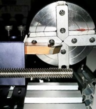
?

How viable does this project look? You're Crazy - you don't even have the software!

Poll closed Sep 18, 2016.
  1. Man, this is perfect - should be a breeze!

    22.2%
  2. It can be done, but you're gonna have to really work to get this going

    44.4%
  3. It can work, but accuracy will be a huge problem

    22.2%
  4. It can be done, but I'm gonna suggest a few modifications

    0 vote(s)
    0.0%
  5. You're Crazy - you don't even have the software!

    11.1%
Multiple votes are allowed.
  1. Johnnycatt

    Builder

    Joined:
    Sep 6, 2015
    Messages:
    17
    Likes Received:
    29
    Johnnycatt published a new build:

    Read more about this build...
     
    #1 Johnnycatt, Sep 18, 2015
    Last edited by a moderator: Sep 29, 2015
    Mark Carew likes this.
  2. Johnnycatt

    Builder

    Joined:
    Sep 6, 2015
    Messages:
    17
    Likes Received:
    29
    Starts off like a lathe...

    It will evolve, but I'm starting with just a basic lathe look: Headstock is mounted, the tailstock is in its place, but not elevated yet. The black plate is just there to show where the cross slide will go.
     

    Attached Files:

    #2 Johnnycatt, Sep 18, 2015
    Last edited: Sep 29, 2015
  3. Ronald van Arkel

    Staff Member Builder Resident Builder

    Joined:
    May 7, 2014
    Messages:
    472
    Likes Received:
    245
    Hello Johnny,

    Looks like it's going to be a great build. I'll keep an eye on your project for sure! Don't let the wife hold you back! :eek: :oops:

    Interesting link to the desktop lathes :thumbsup:.

    -Ronald :confused:
     
  4. Johnnycatt

    Builder

    Joined:
    Sep 6, 2015
    Messages:
    17
    Likes Received:
    29
    Update.. MY ELECTRONICS PACKAGE IS IN!!

    The physical design has morphed just a bit, but not enough progress to show pics. I wanted to make a list of hardware and software I will be using.

    The software is simple (all open source and free):
    My Computer is a simple Dell that was originally purchased around 2010 and is running the Linux Ubuntu 14.04 operating system (but this should all work in Windows and MAC). I am NOT running LINUXCNC - that is a whole different platform and I didn't want to anyone to confuse the the two...

    HeeksCNC:
    This is "CAD/CAM" software, but NOT for a lathe. I am using the "x-y" axis to make a "profile" that the G-Code will cut... I will have to make allowances for that when I draw and when I set up the "CAM" functions (I will have to slow down the speed of travel). These should be easy adjustments - I will just have to figure out "speed and feed" for various materials. It can be downloaded here:
    https://sites.google.com/site/heekscad/news/heekscnc10

    Universal G-Code Sender:
    This is what will send the G-code - most builders will know what this is, but if you are new, you will have to do a little learning on how to "install" it - there is plenty of info on the web for that.
    https://github.com/winder/Universal-G-Code-Sender

    GRBL:
    This is not so much "software" as "firmware." It allows the arduino to interpret G-code. This should be familiar to anyone who is "building" with Arduinos. It will have to be "flashed" to the memory on the arduino. There are a million articles on the web telling how to do that. I felt inclined to include this as it is needed
    https://github.com/grbl/grbl

    AND that is it...

    HARDWARE:

    Arduino UNO:
    Please buy the original from the Arduino site. All mine come form there - it is the heart and soul of the "maker" world and supporting it means "making" moves forward. Yes, there are cheep Chinese knock-offs, but it is NOT worth the savings, IMHO!
    https://www.arduino.cc/


    PROTONEER CNC shield v3.0:
    This fits on top of the arduino and I typically buy them on Ebay. I can usually find a "package deal" that includes an arduino and the Pololu drivers.
    #1 CAUTION: When you buy this on EBAY, be SURE it comes with the POLOLU DRIVERS!! Sellers will "trick" you into buyng the shield without the drivers, so be careful to FULLY READ what they are selling! (once just looked at the pic and when it came in without the drivers, I was PISSED! I went back and read the EBAY page, and it never said it came with the drivers, so I could do nothing -except give a negative rating).
    #2 Caution: Be sure the one you buy comes with the header pins and components installed - it costs a dollar or two more, but no one wants to mess with soldering this stuff together (unless you are into that, then go at it, pal!)

    Pololu DVR8825:
    These are the boys that do all the work! I love them because they work, they are reliable and they are CHEAP! I can get 5 of them for $12-$15 on Ebay ...AND ...AND ...AND they are easily replaceable when you do something stupid and burn one up! You will probably need a fan like the one in you PC to keep them cool. they SHOULD come with a heat-sink for each one - just attach with the included sticky-pads and go!~ I build a little plexi-glass box - we'll cover that when I get to it in the build.
    Caution: once again, be sure the ones you buy have the header pins already installed!! Unless you just get-off on tedious micro-soldering.

    POWER SUPPLY:
    Sometimes I hack these out of old computers, but get a 12v, 24v, or 36v like this if you wanna keep it simple:
    http://www.link-motor.com/views.asp?hw_id=46
    I usually get them from EBAY...


    If done correctly, you can snap together the whole hardware package in about 2 minutes...

    And that is it. I will discuss my motors as we build, but these are like girlfriends: You may not like mine and my tastes may be different, but mine makes me happy, so get your own!
     
    #4 Johnnycatt, Sep 27, 2015
    Last edited: Sep 27, 2015
  5. David the swarfer

    David the swarfer OpenBuilds Team
    Staff Member Moderator Builder Resident Builder

    Joined:
    Aug 6, 2013
    Messages:
    3,219
    Likes Received:
    1,813
    looks like a nice plan so far Johnny.
    have a looked at the now discontinued lathe software LazyTurn ?
     
  6. Ronald van Arkel

    Staff Member Builder Resident Builder

    Joined:
    May 7, 2014
    Messages:
    472
    Likes Received:
    245
    Johnny,


    Just a few quick tips:


    You can get cheap PSUs of ebay that were made for servers. They have a great clean power output and lots of power, plus they output 24 to 48vDC.


    The fuse on that shield you bought needs to be bridged. It probably will burn out so use an external 6A automatic fuse on the DC rail. I'm not at home else I would have sent you and image. I bridge all of the shields I buy by defaults.


    The shield normally is about 8USD and the drivers about 4USD each so you could have known a bit that you were getting just the shield and not the whole package. If you paid over 15USD for it they indeed ripped you of and I would be pissed too. Now, that said, I always had good results returning goods bought from eBay. Negative feedback is a bit harsh from your side don't you think?


    Anyway, I'm here to help ;),


    -Ronald
     
  7. Johnnycatt

    Builder

    Joined:
    Sep 6, 2015
    Messages:
    17
    Likes Received:
    29
    David,
    I had a chance to google LazyTurn, but it looks like it requires Mach 3. I really haven't studied it yet. I am trying to do the whole project as FREE and open-source, so if I can run it on Linux, I'll be happy to try it... the only download I saw was an .exe file. Linux can run them, but you have to use a program called "WINE," and I HATE that program...

    ************************************************************************************

    Ronald,
    PLEASE get me the info on that bridge and fuse... I've been using these shields for a while and I DON'T want that problem... I am a "mechanical" designer, not an "electronic" designer, so I will take ANY advice I can get on the Shields, boards, wires, motors, etc!

    Yes, A "Neg" on Ebay is pretty harsh, but about 10% of his reviews were negative. The picture he showed included the drivers - they were separate but in the same picture. Since "returning" it would have cost almost as much as I paid, I decided to keep it and just give him the "neg."
     
    #7 Johnnycatt, Sep 28, 2015
    Last edited: Sep 28, 2015
  8. Johnnycatt

    Builder

    Joined:
    Sep 6, 2015
    Messages:
    17
    Likes Received:
    29
    I did get a couple of pics.

    I have redesigned the "carriage" and this is it. It will sit "offset" to the lathe's headstock in the same manner as a traditional lathe. The part you are looking at will ultimately be "in front" or "closer" to the user than the headstock.

    The head stock will be partial supported by the "base" you see here. The Carriage will move all the way to the left to find "X = 0" and the carriage will move "inward" (away from the user) to find "Y = 0".

    So, all the design will be done in the X-Y plane and the lower-right corner of the Cartesian grid in a 2D manner**. Moving away from the center of the chuck would be making "X" greater as a positive number and "Y" greater as a NEGATIVE number (which, yes, I know that means "Y" is actually getting less, but were talking in absolute value, here!)

    I am pretty sure this is NOT the way "professionals" do it. BUT this is how I'm gonna do it. This way, I can design projects using software that is meant for 2.5D "carving" and use it for lathe work. It seems to be the best way to set up a simple "profile" for a lathe. I may change it at some point, but the X-Y plane in HeeksCNC is easiest to control.

    I want this to be an EASY step for someone who has a 2.5D carver (Ox-build, Shapeoko, V-Carve, 2030, etc) to make the step to a lathe (and hopefully be able to use their existing software or my FREE options).

    ** I might even be able to modify my plans to run the lathe using .dxf files and a very light-weight program called DXF2GCODE. I used this when I first started out, but would have to "dust it off" to try...
     

    Attached Files:

    #8 Johnnycatt, Sep 28, 2015
    Last edited: Sep 28, 2015
  9. Johnnycatt

    Builder

    Joined:
    Sep 6, 2015
    Messages:
    17
    Likes Received:
    29
    Here is a little bit better view of the back side of the carriage. The tool post is already mounted on the top left of the "carriage."

    The "Y" lead-screw is a bit long, but I was guessing at it's length and decided to leave it a little long until it was mounted. Right now it is about 8" (200mm) long, but will ultimately be cut-down to about 6" (150mm) long and should have about that much travel. Because of that, I will only have about 3" (75mm) of workable space, but with that being the RADIUS, then my "swing would be about 6" (150mm)!! My chuck is only capable of about 4" (100mm) so I should be OK

    (Side note: I own a real 13" lathe and have numerous times machined larger-diameter things using a smaller-diameter "hub" held by my 8" chuck. I am sure I will end up doing that at some point with this lathe, but I am usually "boring" a hole when I do that, so the lead screw SHOULD be out of the way).
     

    Attached Files:

    #9 Johnnycatt, Sep 28, 2015
    Last edited: Sep 28, 2015
  10. Johnnycatt

    Builder

    Joined:
    Sep 6, 2015
    Messages:
    17
    Likes Received:
    29
    Any Ideas on how to "square" the two V-Slot linear rails?

    This is NOT a project for NASA, so I'm happy with just leaving it how it is - I'm not doing surgery or going to the moon, so a couple of .001" here or there are not really gonna matter that much to me! The intent of the project is to make custom hand-rail spindles or "bollisters" not nuclear reactors...;)
     
  11. Johnnycatt

    Builder

    Joined:
    Sep 6, 2015
    Messages:
    17
    Likes Received:
    29
    I am still in the "proto-typing" stages, but I put my Chuck up on the 20x60 rails it will sit on when it's finished to see how far off the Z-axis would be. to my amazement, it is almost dead on, maybe 3 millimeters LOW, so that means the tool post will have to be shimmed UP, which is easier than milling it down!

    You can see in the pic where the Lead-screw and the V-Slot rails are sticking too far inward to where the material will be. The lead-screw will be cut down and the V-Slot rail will be moved back. the Tool bit will also be pushed farther back into the holder to cut down on the "torque" created by the work. This will allow the tool holder to come farther "out" towards the center-line of the material.

    In the pic, you can see a bronze-colored tool bit in the bit holder. That is a Standard E-6 cemented carbide bit. I will be using E-6, AR-6 and AL-6 bits. All are standard items and can probably be picked up and your local Industrial Supply house, but I know Enco has them:
    E-6:
    http://www.use-enco.com/CGI/INSRIT?PARTPG=INSRAR2&PMAKA=383-4022&PMPXNO=940891

    AL-6 (Enco's picture shows it on it's side, the carbide part should be on top for turning and facing):
    http://www.use-enco.com/CGI/INSRIT?PMAKA=383-0032&PMPXNO=940855&PARTPG=INLMK32
     

    Attached Files:

  12. Ronald van Arkel

    Staff Member Builder Resident Builder

    Joined:
    May 7, 2014
    Messages:
    472
    Likes Received:
    245
    Johnny, I saw how you put the flexible coupling on to the motor shaft and Acme screw; I would change that as it will kill the working precision. That coupling is more like a spring and thus your precision may vary up to 1mm.

    let me give you some pictures of the shield when it's bridged:
    IMG_0054.JPG IMG_0055.JPG
    Made some quick picture from the front:
    IMG_0074.JPG
    The highligted square is where the fuse is. I have no idea what the value of that fuse is but might be 3A.

    There is a new shield out, version 3.10, but the Chinese are slow to a adapt and I can't find an original one from Protoneer. This one has support for GRBL 0.9v with PWM Spindle. I'll ask my supplier if they have any info on that.

    To protect your PSU, use a 6A C-breaker in the 12-16V line.

    -Ronald
     
    Johnnycatt likes this.
  13. Johnnycatt

    Builder

    Joined:
    Sep 6, 2015
    Messages:
    17
    Likes Received:
    29
    Ronald,
    Are you just moving the fuse off the Protoneer Shield and into the "+ wire" coming form the PSU?

    I had not thought about that coupling acting as spring.. thanks.. I may replace it with a straight rigid Coupling or drill and tap that one parallel to the shafts.. then put a screw in it to prevent it from moving (springing).


    Also, do you know a quick and accurate way to set the potentiometers on the Pololu Drivers?
     
  14. Ronald van Arkel

    Staff Member Builder Resident Builder

    Joined:
    May 7, 2014
    Messages:
    472
    Likes Received:
    245
    I just leave the fuse where it is and just solder that thick wire to both of it's pins. I use a 45w pencil. Let me see if I can find a good guide on how to adjust the drivers; Normally there is a measure point for the voltage that goes to the driver but on the non-original ones you have to measure from the middle pin on the pot meter. The voltage that you measure is used to set the stepper IC (DR 8825) to let a certain current (A) go through to each coil of the motor.

    What can be found is this: https://www.pololu.com/product/2133 and jump to Current limiting. The two measure point are the middle pin of the pot-meter and ground. Current Limit = VREF × 2, thus if you want to limit the motors at 0.8A the measured voltage should be 0.4v.

    I hope this will get you on your way.

    -Ronald
     
  15. Ronald van Arkel

    Staff Member Builder Resident Builder

    Joined:
    May 7, 2014
    Messages:
    472
    Likes Received:
    245
    About the flexcoupling:

    upload_2015-9-28_11-7-5.png

    upload_2015-9-28_11-7-43.png
    You can see I use plate to mount the motor with 1-1/2" or 40mm spacers. The shaft of the motor should not touch the acme screw else it will just bang against each other when the motor is operational. the flexcoupling is pushing on a shim that I've greased (some bearing would be nice there). On the other side of the plate I use the ballbearing and the lock collar. All these components are pushed together (holding the bottom of teh flexcoupling and not pushing from the top) by hand and tightened up. You might know this but I thought I'll point it out for others as well ;).

    -Ronald
     
    Johnnycatt likes this.
  16. Johnnycatt

    Builder

    Joined:
    Sep 6, 2015
    Messages:
    17
    Likes Received:
    29
    I sell bearings for a living. I can answer this question!!

    The bearing you are looking for is a Koyo# FNT-821. Amazon shows them for $3.39 here:
    http://www.amazon.com/Koyo-FNT-821-Bearing-Capacity-1-43lbf/dp/B007EE5PT6

    You will need 2 "thrust washers" for EACH bearing. Koyo# AS0816. Amazon shows them for $1.25 here:
    http://www.amazon.com/Koyo-AS0821-Thrust-Roller-Bearing/dp/B007EE5C6W

    A "bearing set" will be: ONE bearing and TWO washers!!

    Bearing dimensions (with a washer on each side):
    8mm - inside diameter
    21mm - outside diameter
    4mm - thick

    You will need 2 "bearings sets" for each lead screw. This means I need 4 bearings and 8 washers for my project. Each bearing with it's 2 washers is 4mm thick - it will take 8mm away from the overall usable length of the lead screw. You do NOT need the collar or the coupling to be as big as the outside diameter of the bearing to work!

    As long as you have 4mm between the coupling and the motor on the motor's shaft now, you will not have to use longer spacers.


    This just infinitely increase the accuracy of this project...
     
    Nick Williams likes this.
  17. Ronald van Arkel

    Staff Member Builder Resident Builder

    Joined:
    May 7, 2014
    Messages:
    472
    Likes Received:
    245
    Yup, that would do it nicely, and a great size as well (21mm OD) as the flexcoupling is 20mm OD. I never implemented it in my designs as they are not sold in the OpenBuilds stores. I only use single end supported Acme screws for the Z-axis and it hold up well with just that single shim and some BAT3 grease but the Thrust Bearing would be so much better. I would keep in the flexcoupling as it would greatly reduce abuse on the Acme nut. Talking about the Acme nut, you might replace that with the anti-backlash one in the near future. You will notice some play between nut and screw that might affect the accuracy.

    I also fount this one before: http://www.amazon.com/Needle-Roller-Bearing-Thrust-AXK0819/dp/B00DN5KYT6 . It´s a little bit more open so more grease can be put into it if needed. Now, some here might say that grease is sticky and dirt might build up. For those who say that you can use non-sticking chain lube (for example motorcycle chains). For my builds I just keep it with BAT3 and if light lubrication is needed WD40. I know WD40 is used to clean but it lubricates a bit as well, downside is that it "dries" up.

    Let me draw the Koyo FNT821 bearing in SketchUp; I have to guess the exact size as I could not find an accurate drawing yet.

    -Ronald


    EDIT: I might use the drawings from the INA (Schaeffler) - AXK0821TN
     
  18. Johnnycatt

    Builder

    Joined:
    Sep 6, 2015
    Messages:
    17
    Likes Received:
    29
    the washers are 1mm thick
    the bearing is 2mm thick.
    Both are 8mm ID x 21mm OD

    Grease should not be needed. I cannot see it making a tremendous amount of difference UNLESS it is going to run everyday for long periods of time. Even then, almost any lubricant would be fine. There is just not enough pressure on this to really matter.
     
  19. Ronald van Arkel

    Staff Member Builder Resident Builder

    Joined:
    May 7, 2014
    Messages:
    472
    Likes Received:
    245
    I see, still lubricating stuff feels better for me :D.

    upload_2015-9-28_13-55-14.png

    Do you use SketchUp or are just building as it comes along?

    -Ronald
     
  20. Johnnycatt

    Builder

    Joined:
    Sep 6, 2015
    Messages:
    17
    Likes Received:
    29
    I do not use sketch-up.. I like to think about the model in my head... In my head, the exact length of things doesn't matter... how they are connected doesn't matter. I have a 13" lathe, milling machine, a CNC router and a welder, so I can build any parts I need. That is NOT what I want to do - I want people to be able to buy the parts from the build store or some easily accessible website...

    OpenBuilds should definitely become a dealer for the TAIG lathe components, though...
     
  21. Ronald van Arkel

    Staff Member Builder Resident Builder

    Joined:
    May 7, 2014
    Messages:
    472
    Likes Received:
    245
    Well, the bearings can be ordered from a lot of places all over the world so that's not a big problem there. TAIG I like, it got my eye and could already imagine the things that could be made with it. I was thinking about CNC pipe-cutters, woodworking (although wooden stairs are really rare here so it's less popular). I might be looking into TAIG for Latin America, but not as parts in teh store. people here just can't or won't build things in their head, hehehe. I do by the way, but to get something on paper is a must else it will drive you mad when you are working on a workshop 4x8 feet machine!

    -Ronald
     
  22. Ronald van Arkel

    Staff Member Builder Resident Builder

    Joined:
    May 7, 2014
    Messages:
    472
    Likes Received:
    245
    By the way, shield 3.10 doesn't have any fuse:

    $_57.JPG
     
  23. Johnnycatt

    Builder

    Joined:
    Sep 6, 2015
    Messages:
    17
    Likes Received:
    29
    Justin, that is a great idea... But it violates one of my rules for this build - I want to build this using only easily obtainable items - either from the Build Store or from a reputable website...

    While I can build just about anything, I want anyone who comes across this build to say: "hey, I can do that!" and "hey, that looks easy!"
     
  24. David Bunch

    David Bunch Veteran
    Builder

    Joined:
    Oct 27, 2014
    Messages:
    622
    Likes Received:
    427
    If you have access to a 3d printer, try this plastic part for a coupling. It is parametric & can be made to most any sizes. http://www.thingiverse.com/thing:964680 I modified the rigid coupling from the Mostly Printed CNC project to make this design.
     
  25. winand

    winand Well-Known
    Builder

    Joined:
    Mar 14, 2014
    Messages:
    65
    Likes Received:
    36
    Very interresting build, look foward to the progress! :thumbsup:

    What materials are you planning to work on with this lathe?
    My concern would be the flexing of the extrusion bar (flex increases when longer stock material is used) and
    the flex the v-slot wheels and bearings have.
    I think milling aluminium could be a real challenge if you want to make accurate parts?
     
  26. Johnnycatt

    Builder

    Joined:
    Sep 6, 2015
    Messages:
    17
    Likes Received:
    29
    Lets try to remember that I want this project to be done by people with no experience and little money... free software and low-cost, readily accessible components.

    Let's try to remember that I am NOT looking to make parts for NASA when it comes to accuracy, BUT IF you can offer any "stiffening" options, I'll be glad to incorporate them into the build - as long as they fit the "inexpensive" and "readily accessible" requirements.

    The materials I plan to work are Pine, Brass and Aluminum. I am not planning on trying to "hog" with this unit... it will be making small cuts and running on "automatic." I plan on letting it do mundane jobs over the course of an entire day. I will be running it at work during the day..

    The "static" tool on the carriage may be replaced with a spindle/router. Since the "tool" is $3 and a spindle in $50-$200, I'm trying this first.

    The first job will be to make spindles from my front porch.
     
    #26 Johnnycatt, Sep 29, 2015
    Last edited: Sep 29, 2015
  27. boskap

    boskap New
    Builder

    Joined:
    Jun 23, 2015
    Messages:
    49
    Likes Received:
    3
    Hello
    What Motor will you take for your Lathe
    Not the Stepper , the Main Motor I mean

    thx Peter
     
  28. Johnnycatt

    Builder

    Joined:
    Sep 6, 2015
    Messages:
    17
    Likes Received:
    29
    The Headstock drive motor I will be using:
    http://173.226.255.146:8080/productdetailI2.aspx?dataid=NT12-18-56CB

    I WILL NOT be buying it from the website. They are a pretty popular manufacturer and almost ANY city with an "electric motor dealer" would have it or something comparable. The website says $272, but I can buy it from my local motor shop for around $100 (I live in a city of about 40,000 people).

    Basically, the specifics are (for use in USA/Canada):
    Single phase
    110/220 volt (I'll be wiring it for 110volt, so I can just plug into the wall)
    1800RPM (any RPM between 1725 and 1800 is the same thing - trust me)
    56C frame w/feet

    from there I will be using a 2" sheave on the motor and a 4" or 5" pulley on the Headstock and an "A" belt. I will list the components when they are in place. That should give me around 850 RPM (using the 4" sheave) or 700RPM (using the 5" pulley). I may have to modify the speed after I get it all up and running, but we'll fall off that bridge when we get to it!!
     
    #28 Johnnycatt, Oct 7, 2015
    Last edited: Oct 7, 2015
  29. SlyClockWerkz

    SlyClockWerkz Well-Known
    Builder

    Joined:
    Feb 26, 2014
    Messages:
    94
    Likes Received:
    34
    Cool! First lathe I've seen on here. I'd be interested to see if there are any alternatives to a sherline headstock - to allow the use of larger stock through the spindle bore.
     
  30. openhardwarecoza

    openhardwarecoza Journeyman
    Staff Member Builder

    Joined:
    Aug 9, 2014
    Messages:
    134
    Likes Received:
    138
    As a sidenote, if you need any help with building our own free software, let me know - I would love to get involved in this a little (despite being low on time)

    (github.com/openhardwarecoza)
     

Share This Page

  1. This site uses cookies to help personalise content, tailor your experience and to keep you logged in if you register.
    By continuing to use this site, you are consenting to our use of cookies.
    Dismiss Notice