Welcome to Our Community

Some features disabled for guests. Register Today.

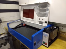
K40 12x24in rebuild (In Original Case)

Discussion in 'Laser Cutters' started by tshilling, Feb 14, 2019.

  1. tshilling

    tshilling New
    Builder

    Joined:
    Jan 17, 2015
    Messages:
    4
    Likes Received:
    27
    tshilling published a new build:

    Read more about this build...
     
    GrayUK and Peter Van Der Walt like this.
  2. Giarc

    Giarc OpenBuilds Team
    Staff Member Moderator Builder Resident Builder

    Joined:
    Jan 24, 2015
    Messages:
    2,992
    Likes Received:
    1,670
    Interesting build. I have been looking at these lately. They are only about $100 more than a good laser diode and can cut thicker material. Had you looked at Scorchworks K40 Whisperer software before deciding to go with the Uno and GRBL?
     
  3. tshilling

    tshilling New
    Builder

    Joined:
    Jan 17, 2015
    Messages:
    4
    Likes Received:
    27
    Giarc,
    I had ripped the original electronics out when I first bought the laser about a year ago, and trashed them. I stumbled on K40 Whisperer sometime after that so I had no real option to use it when I found it. However, I have several machines running GRBL at this time and I love having a consistent workflow between them. I tend to use LaserWeb to generate the gcode, but then use cncjs for actual control as the later is what my big CNC uses and I'm comfortable with it. Had I found Whisperer sooner, things may have turned out different, but with recent releases of GRBL (1.1), Lasers are well supported.

    As to the K40 vs Diodes, I actually use both. I have a 3.5watt laser diode that I attached to my 4x4ft cnc. I use this for marking/engraving after cutting in wood. The K40 on the other hand finally brought the ability to cut with a laser into the shop. Having used up to 100watt CO2 cutters, I do miss the power, but in a home shop, 40 is pretty workable. I have successfully cut through 1/4in (5mm) acrylic and wood. It is forcing me to really rethink how I design and build things, its a rapid manufacturing capability I haven't had since college 15 yrs ago.

    Thanks for the interest and comment
     
    Giarc likes this.
  4. Armadillo Works

    Builder

    Joined:
    Jan 31, 2019
    Messages:
    30
    Likes Received:
    19
    I bought one of the 40 watt Chinese lasers and was able to scrap the crummy Chinese software and hardware key it requires to run the NANO M2 controller by using the Scorchworks K40 Wisperer software. Uses files manipulated or created in Inkscape and saved in its native .svg format for cutting, vector engraving or raster engraving. If you decide to get one; go for the one with the 0 - 30 mA analog meter. The digital shows laser power in percent which is meaningless. Knowing the actual current is more valuable.
     
    GrayUK likes this.
  5. Giarc

    Giarc OpenBuilds Team
    Staff Member Moderator Builder Resident Builder

    Joined:
    Jan 24, 2015
    Messages:
    2,992
    Likes Received:
    1,670
    Thanks for the info on the analog meter. I am seriously considering modifying one of these 40 watt lasers. and making it bigger similar to this build.
     
  6. Giarc

    Giarc OpenBuilds Team
    Staff Member Moderator Builder Resident Builder

    Joined:
    Jan 24, 2015
    Messages:
    2,992
    Likes Received:
    1,670
    I can't believe I just did this, but I ordered a K40. I have all the extrusions, steppers, and drivers I bought a year ago for my 1500 x 750 ORCA (my slightly modified Acro) I started a year ago, but was never able to get the diode to function properly. I think the laser driver board was fried. Also, it is way bigger than I needed. I also have an old CNC shield with DRV8825 drivers that I had on my CNC, but switched over to DQ542MAs when I realized the DRV8825s could not reliably handle the larger machine and steppers.

    I had at one time planned to build a CO2 laser cutter, but I can't help myself and I over size things. Your conversion along with a couple other K40 conversions done previously are inspiring and will constrain me to a size that will fit on my workbench by the window in the garage which will make for easier venting. Now I need to check out some of the other K40 conversions again. :thumbsup:
     
    GrayUK likes this.
  7. GrayUK

    GrayUK Openbuilds Team Elder
    Staff Member Moderator Builder

    Joined:
    May 5, 2014
    Messages:
    1,668
    Likes Received:
    627
    Craig: I hope we can all come along on the journey. :D
    I've been giving this some thought as well.
    The conversion makes a lot of sense. :thumbsup:
     
  8. Armadillo Works

    Builder

    Joined:
    Jan 31, 2019
    Messages:
    30
    Likes Received:
    19
    I found a lot of useful information in and through links in the ScorchWorks web page. The one I ordered had the digital display; so I ended up having to buy a meter and cut a hole. One thing about the digital control is that there had also been some issues with the Laser On/Off button only turning off the display and leaving the laser still on. Very bad since the case did not have any of the safety switches to interrupt the power to the laser if you opened the lid installed. I do know someone who burned a hole in his finger. I have installed these in series with the circuit that senses when the cooling water is not flowing through the tube. Also, with the 0 to 30 mA meter you can regulate the current going to the tube and will find out that you do not need anywhere near 100% to engrave or cut something. Mine will vector engraves with 4mA and cuts 1/8" (3mm) plywood at 10mA. Good luck, have fun and make it a safe man-cave toy!
    Roger
     
  9. Giarc

    Giarc OpenBuilds Team
    Staff Member Moderator Builder Resident Builder

    Joined:
    Jan 24, 2015
    Messages:
    2,992
    Likes Received:
    1,670
    Maybe I should learn Braille first...just in case.
     
  10. GrayUK

    GrayUK Openbuilds Team Elder
    Staff Member Moderator Builder

    Joined:
    May 5, 2014
    Messages:
    1,668
    Likes Received:
    627
    Just keep the video running. We'll tell you if it looks okay!! :ROFL::ROFL::D
     
    Giarc likes this.
  11. Armadillo Works

    Builder

    Joined:
    Jan 31, 2019
    Messages:
    30
    Likes Received:
    19
    Here is a sign you can use!
     

    Attached Files:

    Giarc likes this.
  12. mario sanchez

    Builder

    Joined:
    Feb 13, 2019
    Messages:
    1
    Likes Received:
    0
    hi excuse me what is the long of the belts?
     
  13. tshilling

    tshilling New
    Builder

    Joined:
    Jan 17, 2015
    Messages:
    4
    Likes Received:
    27
    @ Mario,
    I am hesitant to give any exact numbers as there are a lot of variants of the K40. However, mine, for reference were:
    X: 62in (1575mm)
    Y (qty 2): 38in (965mm)

    If I were to buy them myself again (Mind you, I did this with scrap I had) I would be getting 1600mm + 1000mm + 1000mm for 3600mm total. I would of course recommend you get a little extra so you don't end up being short.

    @Everyone else,
    I am glad to see some excitement behind the K40 upgrade. I went back and forth, almost trashing the case myself and building a larger cutting area machine. However, preliminary designs showed it was going to be too big to fit on my bench and cost just too much for what I use it for. I am happy with my choice. I also haven't seen anyone mention it, but since we are talking about blinding ourselves, I did splurge and buy a nice pair of IR laser googles. I think they ran me about $50. I can dig around my email and see if I can find the order from a while ago. So, please, invest in a pair of googles if you are going to play.

    I'm excited to see the different builds and what improvements to the design people come up with.
    Happy building,
    Tim
     
  14. Giarc

    Giarc OpenBuilds Team
    Staff Member Moderator Builder Resident Builder

    Joined:
    Jan 24, 2015
    Messages:
    2,992
    Likes Received:
    1,670
    Another quick question, can you fit a rotary axis in there now?
     
  15. tshilling

    tshilling New
    Builder

    Joined:
    Jan 17, 2015
    Messages:
    4
    Likes Received:
    27
    As built, you will have ~65mm of vertical space between the MDF bed and the air assist (Which is adjustable by 10mm). If you remove the MDF and solve the flatness and mounting issues of the case, you can get up to ~75mm. Personally, I think this is too thin for a rotary system but it depends on what you are going to be making. Personnaly, if rotary is your goal, I don't think the original case is going to suit your needs.
    Happy building,
    Tim
     
  16. Giarc

    Giarc OpenBuilds Team
    Staff Member Moderator Builder Resident Builder

    Joined:
    Jan 24, 2015
    Messages:
    2,992
    Likes Received:
    1,670
    Thanks. I am not 100% sold on rotary. I had thought of having a removable section of MDF in the center. I had even considered raising the case up a few inches and skirting the perimeter and adding a new metal bottom in the skirted area. Then cutting out a section of the bottom of the case where a rotary axis would be installed. But for now I need to focus on just filling a bucket with some distilled water so I can burn some wood for fun.
     
  17. Armadillo Works

    Builder

    Joined:
    Jan 31, 2019
    Messages:
    30
    Likes Received:
    19
    I have one of each and they all have their issues.
    Laser you will have to deal with smoke or fumes.
    Rotary you are going to have to deal with dust and chips.
    Neither are good for your eyes or lungs.

    Both you will want to have as much room as you can get to be able to set up your work piece.
    Laser heads have a optimum focal length and any thing outside that is quickly degraded.
    Rotary cutters have their optimum operating parameters.

    The challenges keep the brain juices flowing!
    Roger
     
  18. BNMaker

    BNMaker Well-Known
    Builder

    Joined:
    Jul 13, 2017
    Messages:
    62
    Likes Received:
    38
    The digital panel machines incorporate many electronic improvements over the original analog-meter units.

    It's the work of ten minutes to calibrate the digital settings with an actual mA output using a multimeter.
     
  19. BNMaker

    BNMaker Well-Known
    Builder

    Joined:
    Jul 13, 2017
    Messages:
    62
    Likes Received:
    38
    If you don't already own a K40, seriously think again.

    The cost of a machine at ~$500 plus another ~$500 on 'improvements' and you could have bought a bigger, better machine and saved yourself a lot of grief and compromise.

    If you already have a K40, great project.
     
    Peter Van Der Walt likes this.
  20. Giarc

    Giarc OpenBuilds Team
    Staff Member Moderator Builder Resident Builder

    Joined:
    Jan 24, 2015
    Messages:
    2,992
    Likes Received:
    1,670
    I bought one, but it was well under $400 when I bought it. So far it has worked for everything I need. I would just like a larger build area and already owned the 2040 vslot extrusions left over from another build.
     
  21. MicroRotors

    Builder

    Joined:
    Feb 15, 2020
    Messages:
    6
    Likes Received:
    1
    Hi Tim,
    I'm about 3/4 of the way into this build, and I see some issues that I'm hoping you could help in solving them.

    • The two printed 20 tooth parts that go onto the 5/16" shaft at the rear do not mate to the belt. Both slip like heck on the belt. I have reprinted them several times in the finest and slowest print settings possible, hoping to fix the issue, but it doesn't. I even cut one in the middle of the toothed section to check what the problem is, and the belt only makes good contact through about 90° and not the 180° as needed.
    • The second mirror mount sticks way out in front of the head so it won't align correctly. I even slotted the screws openings to where the front screw is well into the rise, yet still, a no go.

    If your conversion is working as stated, how did you overcome these issues?

    Regards
    Bill
     
  22. Giarc

    Giarc OpenBuilds Team
    Staff Member Moderator Builder Resident Builder

    Joined:
    Jan 24, 2015
    Messages:
    2,992
    Likes Received:
    1,670
    I was doing this same conversion but I have been side tracked building a lathe. The original poster has not been back here for over a year and this was posted on multiple forums. I am leery of using printed parts I. A critical location like the mechanism that ensures both sides stay parallel and the laser doesn't start a fire due to misalignment.

    I am mulling over different options.
     
    Peter Van Der Walt likes this.
  23. MicroRotors

    Builder

    Joined:
    Feb 15, 2020
    Messages:
    6
    Likes Received:
    1
    Giarc

    Thanks for your reply.
    I'm not worried about using the printed parts or fire as I never leave my K40 is powered up. I'm too far into this to switch to a different build. I managed to solve the 2nd mirror issue, and my only problem was the rear 5/16" shaft connecting the Y-axis's timing for both sides. His 20 toothed printed parts are not correct to accept the belts. I'm looking into a different 5mm to 8mm flexible coupler for the left rear, but the 20 tooth pulley position is making it more difficult due to stepper motor shaft length. The right side would be simple enough by buying an 8mm pulley. My only holdup is that left rear coupler/pulley combo as far as the mechanics are concerned. It appears to be a dollar waiting on a dime scenario.

    I'm trying to stick with the complete set of the stock K40 electronics. The next hurdle will be to make sure the stepping is still correct when using the stock M2Nano board and either K40 Whisperer. I have no issues with the stock K40 and K40 Whisperer as its perfect for my use. I have a side business of cutting micro RC sailplanes with my machine. I'm only looking for a larger cut area to load multiple balsa sheets instead of one at a time. The time it takes to load and cut them individually is chewing at my profit far more than need be.

    Regards
    Bill
     
  24. Giarc

    Giarc OpenBuilds Team
    Staff Member Moderator Builder Resident Builder

    Joined:
    Jan 24, 2015
    Messages:
    2,992
    Likes Received:
    1,670
    I was going to add a spacer of some sort and use a regular aluminum pulley as the shaft coupler. However, then a spacer needs to be added to the unpowered pulley if I recall correctly. As for your steps per mm, I do not know how to correct that in K40 Whisperer or with the M2Nano board. I do not think it is possible. My intention was to scrap the M2Nano so I can use Lightburn. A new Grbl based controller would allow more freedom of software and more control for fine tuning accuracy.
     
  25. MicroRotors

    Builder

    Joined:
    Feb 15, 2020
    Messages:
    6
    Likes Received:
    1
    Do you know what the step angle is for the stock K40 step motors?

    I have been looking at possibly replacing the Y-axis stepper motor with one that has an integrated T8 lead screw. I was thinking that could solve the issue with the stock shafts being too short. They have them with a length of 32mm or 100mm for around $25.00 or so.

    Regards
    Bill
     
  26. Giarc

    Giarc OpenBuilds Team
    Staff Member Moderator Builder Resident Builder

    Joined:
    Jan 24, 2015
    Messages:
    2,992
    Likes Received:
    1,670
  27. MicroRotors

    Builder

    Joined:
    Feb 15, 2020
    Messages:
    6
    Likes Received:
    1
    Thanks, but I looked at Don's page and my numbers on the steppers are not listed. Is there a way to tell from my numbers because I cannot find any information whatsoever about them. My machine was purchased this past April so perhaps his page is to far dated for my machine.

    The stepper in question numbers are printed on the bottom in white ink, not a sticker, and reads as:
    17HA512H 22P2
    FH1909 27 Smooth

    Regards
    Bill
     
  28. Giarc

    Giarc OpenBuilds Team
    Staff Member Moderator Builder Resident Builder

    Joined:
    Jan 24, 2015
    Messages:
    2,992
    Likes Received:
    1,670
    I would assume that it is a 0.9 degree. But, I do not know. I do believe you will have to figure out a way to change the steps/mm if you change the belt and pulleys. In my modification I plan to use a different control board that I can have more control over and the ability to use different software.
     
  29. Giarc

    Giarc OpenBuilds Team
    Staff Member Moderator Builder Resident Builder

    Joined:
    Jan 24, 2015
    Messages:
    2,992
    Likes Received:
    1,670
    Here is a link to where a person made a more robust free software that works with the existin K40 board. I would say that since this board is used in the majority all steppers used would have to be 0.9 degree. meerk40t/meerk40t Now that I finished an important project with mine using K40 whisperer I plan to switch over and try his MeerK40t software. He has a rotary axis option with the original board.

     
  30. MicroRotors

    Builder

    Joined:
    Feb 15, 2020
    Messages:
    6
    Likes Received:
    1
    I d/l it the other day and have played with it, and it is one reason other than filling orders that I haven't torn the K40 down. I only wish there was a little more documentation explaining all the menu features. But I did find out yesterday that, Dave Olsen, the guy behind the software lives in my small desert town. I do believe I need to pick at his brain here in the near future.

    If I change the board, I think I might go with the Mini Gerbil, but I'll have to contact them first and explain my situation.

    Regards
    Bill
     
    Giarc likes this.

Share This Page

  1. This site uses cookies to help personalise content, tailor your experience and to keep you logged in if you register.
    By continuing to use this site, you are consenting to our use of cookies.
    Dismiss Notice