This build is changing directions! I will finish updating article when I get back to my main PC.. Edit: How do I update the Attachments? I removed them from my builds post, but they still show below. I have new images / files and text I wish to add. But I don't see a way to get rid of the old photo attachments before adding the new text / photos / files..
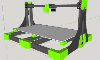
Back on my main PC tonight, here is a "Digital Walk Around" of the new design. I welcome any feedback and advice. Machine Specs 23 x 15 x 6 Build Volume ( I don't need much Z Height but this can be increased). Currently no plans for heat bed ( I am building this to print pla only ) Uses -20x40 and 20x20 V-slot -90 degree Corner blocks -Mini V-Wheels -Custom Machined ( or printed ) axis plates. -300mm Open builds Lead Screws -Dual E3D V6 Hotends (hotend mount courtesy of thingiverse thing:502519) I need to order some more filament so I can print the parts needed to start my build.. Hoping to finish my B.O.M this weekend and place my order for the main parts to start the build. As Soon as I am able to confirm my file accuracy and part list I will be happy to post them ( is sketchup the preferred format or ready to print stl's? ). I am a hands on learner, so I feel I have reached the point were things will become more obvious to me as I build and I can then update and change the files as needed along the way. Any way to delete the original / old attachments so I can update with new photos for this iteration of the design? I was able to update the build image, but am unable to edit the attachments. The new text I have would not match the older version 1 photos of the printer. Would be nice to see a user gallery or such were each user could manage and keep track of there misc. files from one location.
Hi Kyo, Sorry to say, but at the present time there is no provision for deleting an attachment. It will be fixed in the future but may take a while. Tweakie.
Tweakie -- Okay, At least I know I am not going crazy lol. I am not very skilled with forums. I was getting frustrated with myself, sure I was simply missing the obvious. Thanks for the heads up.
Curious to see your motor mount for the x axis. I assume you are using a rank & pinion belt drive concept.
I like the way you did the video Kyo. What software did you use for creating the video? As for stls or skps, it really doesn't make a difference if Sketchup was used for making the stls since the same plugin software that exports the stl is probably the one that imports an stl. If you post stls, the important thing is to load them in slic3r first to make sure they are manifold without slic3r doing repairs. That way they should import cleanly back into Sketchup. I like to post the assembled printer Sketchup file with each part separately componentized. That way people can just extract the individual component pieces themselves for printing/munging/etc and still see how they fit.
Keith -- Yes I am using a Belt and Pinion setup on the X-axis. Dual Lead Screws on the Z-axis and Undecided on how I will run the Y-axis motor at this point. Probably just a simple belt and adjustable pulley setup with fixed belt clamp on the bed carriage. Given the Bed width I have considered Dual Y-axis motors but not sure it is necessary or even better over a single center mounted motor.. The X-axis motor mount is a simple two plate design each 1/4 thick. Lower plate mounts the motor and Upper plate secures the hotend mount. The section on the bottom plate were the motor attaches to I have drawn up to be 1/8 thick to raise the motor away from the build plate as much as possible. I use a Open Source program Called Cam Studio. I currently have Cam Studio 2.7 It has plenty of options , outputs great video and the huge bonus for me ( I run 3 monitors) is I can tell it which monitor to capture full screen. Depending on your computer hardware it does take a bit of adjustment to get clean videos but once set, it is a set and forget deal. Yeah the machine and most of its parts have been designed in sketchup 14.1.1282. STLs would be exported via this plugin (https://github.com/SketchUp/sketchup-stl) How ever I have only been using it on and off for 6-8 months or so and am still learning every day. As such a few of the parts were done in freecad. So far each item is a individual component and then I place those in groups to manage them a bit easier. I don't think I will do a 100% complete sketchup file. my computer is just not powerful enough to render a larger file that has all the nuts, bolts, screws and misc hardware.. All parts to be printed show as Solid Objects ( Manifold) within sketchup but I have not as of yet ran them through Silic3r. With the exception the of the Z-axis motor mounts. I already printed 2 of those as test pieces and made some changes. ( more space for motor, removed overhangs, extra bracing)
Kyo, something you might want to consider. Your two 20x20 extrusion uprights on each side - place them the right distance from each other (43mm inside distance) and the Mini V Wheels mounted on the Mini Wheel plate will fit inside between the 20x20 extrusion uprights instead of on the outside. That way you can use the existing Mini Wheel plate instead of having to make or print one. The Mini Wheel plate uses the eccentric spacers for adjusting wheel tension and 43mm works for half way between full lose and full tight on the eccentric. I think you can find a way to run the acme screw between the mini wheels and mount a nut for it.
Thank for the Cam Studio intro!!! I'm dnlding it now. I used to have a great tool for that but they quit supporting it. Cam Studio looks like just what I want. I sell my own software and I have online tutorial videos that need redone and Cam Studio I think will do it greatly. Videos like this are a great sales tool for software and I'm think of using it for printer sales also. https://github.com/SketchUp/sketchup-stl that plugin installs both import and export and is probably the most widely used by Sketchup users. "my computer is just not powerful enough to render a larger file that has all the nuts, bolts, screws and misc hardware" Mine Too!!! I leave off the nuts, bolts, etc - just the extrusions, printed parts, plates, wheels - just to give the layout. I find that Sketchup and Slic3r do not always agree on what is manifold (different logics I guess). Slic3r has a great "Repair STL file" on it's File menu. Sometimes I have to repair an stl with that feature, which produces a obj file, then load that obj in Slic3r and export it as an stl and import that stl into Sketchup to get a clean, slicable object back in Sketchup to work with.
I opened the parts to be 3d printed in slic3r, My two top bearing supports needed repaired then I followed your instructions and got the repaired files back into sketchup. The other files checked out okay so far. Thanks. I also liked your idea of mounting the wheels inside the 2 v-slot uprights versus on the outside like I had it. I still used a custom plate to do it, but this plate is much smaller and the whole assembly is more compact. Doing it this way also gained about 1/2 in Z print height up to 6 1/2 from 6 using the 300mm openbuilds lead screws. Not much but still more then I will need. I need to print long and short items. A different acme nut might allow me to use the openbuilds mini plate. But from what I modeled up it looks like the wheels would interfere with the nut the way I have the lead screw running.
Glad the Slic3r trick worked for you. Also, there is always the https://netfabb.azurewebsites.net/ repair if Slic3r can't fix it. You need a MIcrosoft account to use it but it's just an email/password signup, no biggy. Ah, yes, fitting some kind of acme nut in that mini plate turned out to be harder than I thought. Like you, I figured that the Nut Block would just slip right in. I like the way you are doing it with the Nut Block and an over-height plate. I'm looking at using the Nut Plate instead. I'm using 35mm long bolts for the wheel axles, then bolting a plastic cover to them that has an extension between the wheel that the Nut Plate presses into. I actually screwed up making my piece for the Nut Plate, it looks like a 8 sided nut instead of a 6 sided, but that shouldn't change the fit. Not sure I like this idea, or yours better - I'll just have to build it out someday and find out (not sure whether that cover will look "snazzy" or "gaudy") .
Kyo, I like this printer design very much. Your concept for the H-frame bed is very similar to an upgrade I am considering for my gMax printer. My one concern with this style (based on what I am experiencing from the current gMax design) is that because it's centered over the central left-right support, this may have a tendency to dive bomb when you get to the full front or rear path under acceleration. I.e. there is nothing stabilizing it front to back to keep inertia tipping it when the gets moving or slams to a stop changing direction. You may consider using dual left-right supports or a wider plate so that the wheels are spaced out a little further on the rail to give it a little more stability. Hopefully this makes sense. - chris
Hey Chris! I think I know you from somewhere... Doesn't this look a lot like Justin's DoubleWide gMax? (Kyo, that's a complement, the three of us are gMax owners and have been heavily modding our machines ) It reminds me of this: http://gcreate.com/forum/viewtopic.php?f=6&t=308&sid=aac1409a5e953100b837c6290e5b099b
Ray!!! Now that you mention it, I do see the similarities. Think the one thing missing is the sky-scrapper spool holder. Kyo, this really does look like a solid design. Can't wait to see the final build.
The sky scraper is easily avoided with a filament guide tube, much like how makerbot does it. In the future, I'd like to put the spool on the moving system of an OX-style printer so that it's on one end of the X gantry and always stays in line with the extruder carriage. Then, some teflon or nylon tubing to somewhat guide it to the [still] direct drive extruder. The tubing flexing by making more or less of an upward arc is how I plan to mitigate the filament snapping around and potentially causing a tangle.
--Keith Very nice, I never would have thought to use the nut plate in that manner. I sometimes have trouble thinking outside the "box". Was talking with a neighbor the other day who volunteered to cut out any custom plates I may need for the build on his mill in exchange for the printed parts he needs for his OB1.4 build. I already had the aluminum sheet so win win for the both of us.. -- Chris I do have concerns about it wanting to tilt during full forward/rear extension the bed will be heavier then most.. I have a couple of ideas to handle it ( hopefully lol ) I have to test them and see which works best. --Ray Thanks for the link to the doublewide Gmax. I missed that one while researching larger printers. I will have to read his thread when I get home. I can definitely see the similarity's even on my phone.. Will be nice to see how he handled some of the issues with going with a larger machine. Electronics for this and the delta-six project / Some more filament / One e3d hot end/ most hardware all on there way. Next payday, motors / v-slot / wheels / lead screws and belts.