Welcome to Our Community

Some features disabled for guests. Register Today.

Desktop PCB Maker

Discussion in 'CNC Mills/Routers' started by PhotoSgt85, Jan 31, 2017.
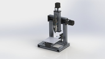
  1. PhotoSgt85

    PhotoSgt85 Well-Known
    Builder

    Joined:
    Jul 27, 2015
    Messages:
    54
    Likes Received:
    66
    PhotoSgt85 published a new build:

    Read more about this build...
     
    Derekz, Steve Mc and MaryD like this.
  2. Steve Mc

    Steve Mc New
    Builder

    Joined:
    Nov 21, 2016
    Messages:
    8
    Likes Received:
    4
    Will be watching this build with interest. I'm currently putting together a C-Beam with the same primary function of milling PCBs in mind with the added advantage of being able to cut plates for a much larger machine later when I learn enough. Also had in the back of my mind the possibility of adding the 3D printing and laser capability to it later on as well. Nice to see someone else with similar thinking.
     
    Derekz and PhotoSgt85 like this.
  3. PhotoSgt85

    PhotoSgt85 Well-Known
    Builder

    Joined:
    Jul 27, 2015
    Messages:
    54
    Likes Received:
    66
    I just finished a C Beam XL build so capacity isnt what I need. My lab makes a lot of custom PCBs that we currently do with photo sensitized boards. I wanted a machine that fits easily on a desk (or workbench as it were) that could produce the same quality boards without the time investment, as well as drill holes for the through hole components. If you are watching this expect that I will add some form of containment as I imagine being in the same room as this would be a bother if you had to breathe in all the dust. Thanks for commenting!
     
    Derekz likes this.
  4. Steve Mc

    Steve Mc New
    Builder

    Joined:
    Nov 21, 2016
    Messages:
    8
    Likes Received:
    4
    Out of interest, have you tried milling a board on the XL? Just wondering how suitable a C-Beam would be for this
     
  5. PhotoSgt85

    PhotoSgt85 Well-Known
    Builder

    Joined:
    Jul 27, 2015
    Messages:
    54
    Likes Received:
    66
    I haven't yet, just finished it yesterday and have only done one thing on it, which was to run a simple g code file through it. So the lead screws move the nuts 8mm per revolution, so if you divide your stepper driver steps per revolution by the 8mm you should get the displacement per step. if you are using something like the A4988 stepstick you are eighth microstepping (8 microsteps per step). On a 1.8 degree per step motor (fairly common) you have 200 steps per rev, so 1600 microsteps per revolution. With that you would have 200 steps per millimeter, or .005 mm theoretical resolution. I say theoretical because there is error due to backlash and the possibility that your stepper could lose a step.

    To answer your question though I see no reason why it wouldn't be accurate enough, so long as care was taken in setup. I dont have any PCB bits currently, but once I have one Ill run a test. I am going to be looking into bits that I can use my Dremel with this build.
     
  6. Theodewijs

    Builder

    Joined:
    Jan 16, 2018
    Messages:
    2
    Likes Received:
    1
    For making pcb's this diy machine is way too expensive. Although it looks nice, but I built a 3d diy machine for a third of the price.
     
  7. GrayUK

    GrayUK Openbuilds Team Elder
    Staff Member Moderator Builder

    Joined:
    May 5, 2014
    Messages:
    1,668
    Likes Received:
    627
    Theodewijs.
    We'd be really keen to see this machine, if you have any pictures of it? :)
    Gray
     
  8. Theodewijs

    Builder

    Joined:
    Jan 16, 2018
    Messages:
    2
    Likes Received:
    1
    It's an Anet A6 3d printer. If you google around you find really cheap prices. Here's the picture:
     

    Attached Files:

    GrayUK likes this.
  9. Quas7

    Quas7 New
    Builder

    Joined:
    Sep 19, 2017
    Messages:
    8
    Likes Received:
    0
    Hi,

    I am on the same track for primarily engraving PCBs. Resolution should be totaly fine (can go for 32 micro steps wit DRV drivers, if needed) but the bed has to be tightly leveled as well as cutting width will vary at least for V-bits. And, according to Metalguru (https://openbuilds.com/threads/upgrading-the-“old”-c-beam-machine.6904/page-3#post-63193) leveling and keeping it level can be tricky with the stock C-beam setup. Looking at the Y-gantry and its wheels with short distances makes this very plausible, at least for me.

    Also, the PCBs tend to be bend or bowed if not fixed to the bed, i.e. with a vacuum chuck or double sided tape.
    After googling around, it seems to be a good strategy to combine a resist with the engraving for the first trials. If cuts are not deep enough, you can just etch it afterwards and get a perfectly clean PCB instead of throwing it away.

    I am still waiting for my C-beam parts but I already ordered 500mm SBR12 linear rails to support the bed edges, similar to Machineguru's setup here: https://openbuilds.com/builds/c-beam-machine-too.3637/

    Cheers,
    Till
     
  10. Quas7

    Quas7 New
    Builder

    Joined:
    Sep 19, 2017
    Messages:
    8
    Likes Received:
    0
    Hi Theodewijs,

    I guess, you are referring to 3D printer setups, that rely on etching in the end?
    Etching PCBs With A 3D Printer
    Entry-Level 3D Printer Becomes Budget PCB Machine

    For me, PCB engraving is meant to avoid etching and get the time consuming drilling done together with the layout. Putting press fit vias into the board is already enough of a hussle. :banghead:
    At least, I would personally like to get rid of drilling and etching ...

    My Folgertech FT-5 with MGN12 rails could be up to the light engraving task. There is a "CNC" kit for it (long sold out - and a Folgertech CNC is advertised...). But, regarding material price of the FT-5 kit + CNC addon and build time this is already close to a C-beam router and it still would not cut aluminum at all. Also, I strongly believe, the FT-5 will start to dismantle and break sooner or later - to much leverage and vibrations in the whole fragile 2020 structure.

    Of course, if you go for pre-inking and scratching, modding a 3D printer is a very nice approach.

    If you get a PCB fine pitch direct engraver out of the A6, I will be one of the first adopters. :)
    But I believe, the belt backlash and soft frame of the A6 are not up to this task. But, please prove me wrong! :)
     
  11. Giarc

    Giarc OpenBuilds Team
    Staff Member Moderator Builder Resident Builder

    Joined:
    Jan 24, 2015
    Messages:
    2,892
    Likes Received:
    1,610
    GrayUK and Rick 2.0 like this.
  12. Quas7

    Quas7 New
    Builder

    Joined:
    Sep 19, 2017
    Messages:
    8
    Likes Received:
    0
  13. Giarc

    Giarc OpenBuilds Team
    Staff Member Moderator Builder Resident Builder

    Joined:
    Jan 24, 2015
    Messages:
    2,892
    Likes Received:
    1,610
    Cool! That should work.
     

Share This Page

  1. This site uses cookies to help personalise content, tailor your experience and to keep you logged in if you register.
    By continuing to use this site, you are consenting to our use of cookies.
    Dismiss Notice