Welcome to Our Community

Some features disabled for guests. Register Today.

Delta-Six

Discussion in '3D printers' started by Sage, Jan 26, 2014.
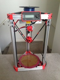
  1. Sage

    Sage Well-Known
    Builder

    Joined:
    Dec 14, 2013
    Messages:
    32
    Likes Received:
    67
    Nugz likes this.
  2. Mark Carew

    Mark Carew OpenBuilds Team
    Staff Member Moderator Builder Resident Builder

    Joined:
    Jun 28, 2013
    Messages:
    2,741
    Likes Received:
    2,407
    This is going to be good I can already tell :)
     
  3. cameron

    cameron New
    Builder

    Joined:
    Dec 16, 2013
    Messages:
    9
    Likes Received:
    3
    Nice man, looking forward to seeing some build pictures, those corners look real good, might sketch some up and see how they look.
     
  4. Bryant

    Bryant New
    Builder

    Joined:
    Dec 6, 2013
    Messages:
    33
    Likes Received:
    7
    This looks great. I need to do a 3d printer after I finish my Routy CNC-router. I'll have to get someone to print the parts.
     
  5. Josh Mascote

    Builder

    Joined:
    Jan 30, 2014
    Messages:
    39
    Likes Received:
    9
    I would like to try this build. Do you have any pictures of a finished build, I am having trouble visualizing how the 3d printed part fits in??
     
  6. Sage

    Sage Well-Known
    Builder

    Joined:
    Dec 14, 2013
    Messages:
    32
    Likes Received:
    67
    Here are some shots of previous versions. I'm currently waiting on more plastic. :cool:
     

    Attached Files:

    Public Do Omens likes this.
  7. Josh Mascote

    Builder

    Joined:
    Jan 30, 2014
    Messages:
    39
    Likes Received:
    9
    Looks good. This helps a ton. Looks like you have some rods in addition to a carriage? I would be interested in getting some dimensions for parts. Let me know if you need some help, I would like to build something similar in the next month or so.
     
  8. Josh Mascote

    Builder

    Joined:
    Jan 30, 2014
    Messages:
    39
    Likes Received:
    9
    Do you happen to have the OpenSCAD file for this part?
     
  9. Robert Hummel

    Robert Hummel Custom Builder
    Moderator

    Joined:
    Nov 14, 2013
    Messages:
    978
    Likes Received:
    714
    Simply awesome !

    Think I know what printer I'm attempting lol ;)
     
  10. Mark Carew

    Mark Carew OpenBuilds Team
    Staff Member Moderator Builder Resident Builder

    Joined:
    Jun 28, 2013
    Messages:
    2,741
    Likes Received:
    2,407
    @Josh Mascote
    Planing a 20x80 version? :cool:
     
  11. Sage

    Sage Well-Known
    Builder

    Joined:
    Dec 14, 2013
    Messages:
    32
    Likes Received:
    67
    I do. As I said I'll work on cleaning it up the project and combining it into a single file. Unfortunately the internet connection at my house has been down for 4+days. Once that is back up and running I'll upload the goods. In answer to your earlier question, yes I have carriages and effector. I've also got 3 or 4 rod/hinge designs, but so far nothing beats simple Traxxas ball joints with rubber bands connecting the rods.

    I'm using mini V-wheels on my carriages, so the spacing for 20x40 is ~51.90mm. I made aluminum plates with 7.14mm holes spaced at 51.90mm in X and 31.90 mm in Y. This will create a back plate that will run with eccentric spacers on 20x20 or 20x40.

    If you want the SCAD for something simple, it may be quicker for me to just make a change and upload another .stl
     
  12. Josh Mascote

    Builder

    Joined:
    Jan 30, 2014
    Messages:
    39
    Likes Received:
    9
    I am having a friend printing the parts and he asked if I had the OpenSCAD file due to the overhangs.

    *Edit: Don't think it didn't cross my mind though. The 20x40 is out of stock completely. I had considered maybe a 20x60 or 20x80 variation, but I think it might be overkill. I mean if the price was the same maybe.
     
    #12 Josh Mascote, Feb 6, 2014
    Last edited: Feb 6, 2014
    Mark Carew likes this.
  13. Josh Mascote

    Builder

    Joined:
    Jan 30, 2014
    Messages:
    39
    Likes Received:
    9
    Friend who is printing the parts for me was concerned about the overhangs. I was actually mostly interested in the OpenSCAD file for the vertex connectors at this point.
     
  14. Glenn West

    Builder

    Joined:
    Dec 5, 2013
    Messages:
    23
    Likes Received:
    7
    nice build. Looking forward to your update with scad files as well.
    I like the electronics on top.

    Looks like your using mini-vwheels, just wondering if your current version is going with a printed carriage.

    Are you getting rid of the rods as well?

    Im currently using openrail and feel no slope in the carriages with metal plates. So was considering going with
    your design for version 2, without rods, and a more celeberus style carriage riding on v-slots.
     
  15. Sage

    Sage Well-Known
    Builder

    Joined:
    Dec 14, 2013
    Messages:
    32
    Likes Received:
    67
    Finally got my internet connection up and running again... you don't realize how much you "need" something until its gone. ;)

    Anyway I added a few pictures of my current progress on this version of the build, and more importantly uploaded the OpenSCAD source files for the primary part (Vertex). I've been working on some magnetic arms because zero play is super appealing, but so far Traxxas ball joints + rubber bands and carbon fiber arms beat everything. I got my first set of arms from here (no affiliation):
    http://www.tridprinting.com/Mechanical-Parts/#3D-Printer-Rod-Kit

    @Glenn West , Yes I got rid of the rods. One of the main reasons for going with V-Slot vs. standard extrusion. I did a version with 15x15 extrusion and 8mm rods, but it was still torsionally weak when the carriages were in the center of the vertical travel. The current 20x40 version is super rigid all around. Winner!
    IMG_0980.jpg


    If I come up with something super awesome for the carriages/arms or finish the build I'll post more stuff. Let me know what you guys think, or if you need help getting the basics up and running. I've definitely got carriage and effector files if someone really needs them.
     
  16. Glenn West

    Builder

    Joined:
    Dec 5, 2013
    Messages:
    23
    Likes Received:
    7
    Like to see the rest, and including the plate design.
    Neat you added the springs.

    Looks like also u included the limit switch in the vertex for the upper I assume.

    Also the design for the covers on top would be nice.

    Looking at this, it also looks nice to fully enclose, with a e3d or a pico, should be close
    to printing teflon. :)

    I use the same arms on mine at the moment.
     
  17. Mark Carew

    Mark Carew OpenBuilds Team
    Staff Member Moderator Builder Resident Builder

    Joined:
    Jun 28, 2013
    Messages:
    2,741
    Likes Received:
    2,407
    This build is really looking great @Sage ! :thumbsup:
     
  18. Glenn West

    Builder

    Joined:
    Dec 5, 2013
    Messages:
    23
    Likes Received:
    7
    Was going thru the openscad for your vertex. Really nice work.
     
  19. Sage

    Sage Well-Known
    Builder

    Joined:
    Dec 14, 2013
    Messages:
    32
    Likes Received:
    67
    Thanks guys. Like I said in the build, I've been working on this off and on for a while.

    @Glenn West, What plate are you talking about? The bed or something else?

    Yeah, the springs were actually a failed experiment. They look better, but tend to slide up and down the arms. :banghead: Perhaps I'll whip up a printed collar, but for now its back to rubber bands, and magnets.

    Yes, the vertex has holes/mount for a standard micro-switch. With the new Repitier I've started doing all the endstop adjustment in software.

    For the top covers I was just cutting a piece of lexan to size and fitting it to the extrusion slots. That doesn't work quite as well with the 20x40 because the slots are larger. I've thinking about another solution now, but I may just pick up thicker lexan.

    The design won't easily enclose because of the the carriages running on the sides of the extrusion. I've thought about printing a carriage that runs in the inside extrusion slots (no bearings/wheels) but then I wouldn't need V-Slot. o_O and getting the pretension correct would be problematic.

    Let me know if you print the Vertex, and what you think of it.
     
  20. Glenn West

    Builder

    Joined:
    Dec 5, 2013
    Messages:
    23
    Likes Received:
    7
    Was talking about your carriage plates actually. Are they standard open builds ones?

    I was thinking of using a adapterr on front of the vertex, to serve as a point to mount lexan or equiv.
    Then U could space out enough to avoid the carriages.

    Yep I definetly will print it out and let u know.

    I love the elegance of a Delta.

    Now if I can only figure out the magnetic rod ends.
     
  21. Steven

    Steven New
    Builder

    Joined:
    Feb 25, 2014
    Messages:
    1
    Likes Received:
    0
    Very nice build!:thumbsup: Love your Delta design. Looking forward to see the complete design and build one !
    But seems all v-slot are out of stock today :( .. anyone know when they will back to stock?
     
  22. Mark Carew

    Mark Carew OpenBuilds Team
    Staff Member Moderator Builder Resident Builder

    Joined:
    Jun 28, 2013
    Messages:
    2,741
    Likes Received:
    2,407
  23. The Dude

    The Dude Well-Known
    Builder

    Joined:
    Jan 2, 2014
    Messages:
    243
    Likes Received:
    102
    I'm curious as to whether these parts have to be 3D printed or if they can be cnc machined?
     
  24. Josh Mascote

    Builder

    Joined:
    Jan 30, 2014
    Messages:
    39
    Likes Received:
    9
    I think you certainly could, but unless you simplified the design, it would take several passes in several different positions to make. The holes on the inner most part would be interesting to make, not sure how you would do that.
     
  25. Robert J Rissell

    Builder

    Joined:
    Apr 11, 2014
    Messages:
    9
    Likes Received:
    2
    57.82 % on the printout of the first vertex on my Prusa I2. I've got my V-slot and related parts in, waiting for printed parts from a Kossel Mini for the end-effector. I'm gonna try just the Delrin wheel kits with eccentric spacers on 2; mounted on the Openbuilds carriage plates.

    J-head with Air Tripper extruder (3mm). Eventual plans to mount a diode laser to cut out balsa sheeting to support my R/C aircraft building habit.

    I'm hoping the 2mm GT2 belt is beefy enough for this application.

    Robyn
     
    Thamli and Mark Carew like this.
  26. Mark Carew

    Mark Carew OpenBuilds Team
    Staff Member Moderator Builder Resident Builder

    Joined:
    Jun 28, 2013
    Messages:
    2,741
    Likes Received:
    2,407
    Sounds like an awesome project @Robert J Rissell looking forward to it
    The GT2 belt will do the job nicely.
    Have fun and please share your build with us, Thanks :thumbsup:
     
  27. Robert J Rissell

    Builder

    Joined:
    Apr 11, 2014
    Messages:
    9
    Likes Received:
    2
    Update 2. 2 vertices printed; 4 to go. I've got a bear of a job getting the 1st layer laying down right on my Prusa I2 due
    to the fact that I don't have a reliable Z-stop. Start - observe - rip up - restart: repeat until printing. Even when I've got it
    past that first layer, snagged wires and jumped belts cause a spaghetti mess. This is one feature I am looking forward to eliminating
    with the Delta design.

    I also discovered that I miscalculated on my BOM for V-Slot rail. 1 m = 300 mm + 700 mm for a triangle side and a tower..
    Three 1 m pieces equal 3 towers on a base.... You see where this is leading.... Yes, back to the OBP Store.

    Kossel Mini kit and electronics show up tomorrow; RAMPS 1.4 and an LCD panel with SD card port driving 4 NEMA 17 motors.

    Anyone need any extra Kossel Mini corners (Blue plastic)? Yours for the shipping. Are there such things as give-away piles
    at various Makerspaces (Yeah, could see it be a clutter issue if left un-checked..)?
     
  28. Sage

    Sage Well-Known
    Builder

    Joined:
    Dec 14, 2013
    Messages:
    32
    Likes Received:
    67
    @Robert J Rissell
    Hey, its awesome to see someone else printing out these parts and checking out my build. Sorry about the lack of updates, I've been getting crushed at work.
    Anyway, I've got my build mostly finished now. (printing well) and I'm super happy with the frame/openbuilds parts. I posted up some more of the key components. Plates for holding the idler w/bearings in the top vertices, carriages, and effector for standard ball joints using M3 hardware. There is also a plastic T-nut for M3 hardware to help hold the microswitches in place. Everything is setup in configurable OpenSCAD files, and I included the .STL's for those that don't want to mess with tweaking there own design. A few interesting new bits that set this build apart:
    1. The effector supports snapping in an LED light ring. Found here
    2. I'm really happy with the tool-less belt connection on the carriages.

    Please let me know what you think, and if you get stuck with the build
    -Sage
     
  29. Sage

    Sage Well-Known
    Builder

    Joined:
    Dec 14, 2013
    Messages:
    32
    Likes Received:
    67
    @Glenn West
    Just realized that I never directly answered you about the carriages. I'm not using standard Openbuild plates because the mini-v ones only support a 20mm span. I'm using standard 3" X 1/8" aluminum stock we can pick up here in the states at the local Home Depot. I included the printed template I used to punch the pilot holes when I drilled the plates. Need to get a CNC machine up and running so I can mill some really precise ones. :D
    Anyway, like I said before, in the end I made plates with 7.14mm holes spaced at 51.90mm in X and 31.90 mm in Y. This will create a back plate that will run with eccentric spacers on 20x20 or 20x40.

    Did you ever print the Vertex? I ended up punting on the Magnetic joints. Worked SUPER awesome for backlash, but didn't have much torsional stability. I'm sure I'll get bored and go back eventually, but right now the simple ball joints + spring is the best elegant solution I've seen. I made little plastic clips that fit over the carbon fiber rods and hold the spring.

    -Sage
     
  30. Robert J Rissell

    Builder

    Joined:
    Apr 11, 2014
    Messages:
    9
    Likes Received:
    2
    Hi Sage!

    Was looking to make a Delta and your solution seems to be an excellent use of strong, off-the-shelf components now that V-Slot
    channels are now available.

    I've gotten a good start on the plastics, rails and some test-assembly.

    Just a few comments in your thread here and then I'll start a build of my own.

    I'm using the standard Carriage Plate with 2 Eccentric bushings... Still need to figure out how to get a no-slop fit around the 20x40.

    Also, 30mm long bolts for the end don't give me enough bite into the threaded ends. I'm going to try 35mm instead.

    Here's the one vertex attached to a rail that I've done as an experiment.
     

    Attached Files:

Share This Page

  1. This site uses cookies to help personalise content, tailor your experience and to keep you logged in if you register.
    By continuing to use this site, you are consenting to our use of cookies.
    Dismiss Notice