Welcome to Our Community

Some features disabled for guests. Register Today.

CoreXY W/ Fixed Build Plate & Enclosure

Discussion in '3D printers' started by JOSH.PIERCE, Oct 12, 2015.
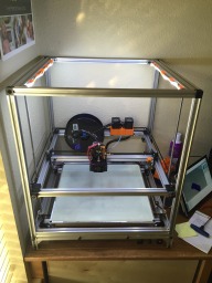
  1. JOSH.PIERCE

    Builder

    Joined:
    Aug 17, 2015
    Messages:
    18
    Likes Received:
    27
    JOSH.PIERCE published a new build:

    Read more about this build...
     
  2. JOSH.PIERCE

    Builder

    Joined:
    Aug 17, 2015
    Messages:
    18
    Likes Received:
    27
    Couple pictures of the build so far. Waiting for parts to come in still.

    [​IMG]

    [​IMG]
     
  3. Mark Carew

    Mark Carew OpenBuilds Team
    Staff Member Moderator Builder Resident Builder

    Joined:
    Jun 28, 2013
    Messages:
    2,741
    Likes Received:
    2,407
    Great looking build so far @JOSH.PIERCE I was studying the build a little and I thought about a way that you may be able to get away with not cutting the side plates and thought it may help.
    Everything on this example also uses stock parts as well.
    3D PRINTER 3-1.JPG
    Idea without having to cut the plates
    example no cut plate.jpg
    SketchUp file is included
    Hope this helps
     

    Attached Files:

    Adam Filipowicz likes this.
  4. Keith Davis

    Keith Davis Veteran
    Builder

    Joined:
    Dec 11, 2013
    Messages:
    506
    Likes Received:
    393
    Mark, what wheel plate are you using, I don't recognize it?
     
  5. JOSH.PIERCE

    Builder

    Joined:
    Aug 17, 2015
    Messages:
    18
    Likes Received:
    27
    Mark, That is a really good idea. Wish i hadn't modified the plates yet or I would have tried that. Need to take a picture of the gantry, got it all put together this weekend. Love how this stuff can be put together so many different ways.
     
    Mark Carew likes this.
  6. stargeezer

    stargeezer Journeyman
    Builder

    Joined:
    Feb 20, 2015
    Messages:
    328
    Likes Received:
    117
    Hi Josh, great build idea! I can't wait to see how you solve all the belt issues. I admit that I've only glanced at most of the Core XY designs. They seem like a solution looking for a problem :) How ever, yours appears to be a much better (simpler) concept and anything over 300mm gets me excited.

    One thing I wondered about is your use of a Nema 17 stepper for the Z axis? It seems to me, that with the load spinning 4 leadscrews and lifting a 400x400mm build platform with a kilo or two of printed material on it, the load may exceed the abilities of the humble 17. Perhaps a Nema 23 270ozin stepper may help avoid any problem. Since you only have one stepper in this axis with careful selection of the stepper you can stay safely within the limits of a Ramps chip. And even if you need to swap to a slightly stouter Ramps chip (4825?).

    Keep up the great Work and please, keep taking pictures.

    Larry
     
  7. JOSH.PIERCE

    Builder

    Joined:
    Aug 17, 2015
    Messages:
    18
    Likes Received:
    27
    Thanks Larry.

    I am hoping that because the build platform is fixed the nema17 will work since i am only lifting the gantry. The ones i got are 84 oz/in, so i am hoping they will be enough for the Z. Time will tell on that one, if not i will step it up to a 23.

    Got some more work done on it over the weekend and finally got some pictures. Build plate is just sat there for my amusement. Will be making some brackets to use for leveling and raise it off the base for my heater to attach to the bottom.

    Still waiting on some key parts to come in, hopefully they will be here soon.

    IMG_2570.JPG IMG_2571.JPG
     
  8. stargeezer

    stargeezer Journeyman
    Builder

    Joined:
    Feb 20, 2015
    Messages:
    328
    Likes Received:
    117
    Well, I feel foolish! I know I read that you intended to have a fixed build platform and by the time I was typing I spaced it completely out! :)

    Thanks for the pics. I know I really enjoy looking at all the different ways other folks solve problems and I'm sure others share my voyeurism too. Maker porn, I guess. :)

    Be well!
    Larry
     
  9. Mark Carew

    Mark Carew OpenBuilds Team
    Staff Member Moderator Builder Resident Builder

    Joined:
    Jun 28, 2013
    Messages:
    2,741
    Likes Received:
    2,407
    Thats the 20mm V-Slot plate ( you have to click on the 20mm option in the right, might need to change this :) )
     
  10. Keith Davis

    Keith Davis Veteran
    Builder

    Joined:
    Dec 11, 2013
    Messages:
    506
    Likes Received:
    393
    Ah, yes, the second image in the galley list. Can't believe I never saw that before :oops:. Looks like a possible candidate for a dual extruder mount :D. Thanks!
     
    Mark Carew likes this.
  11. Keith Davis

    Keith Davis Veteran
    Builder

    Joined:
    Dec 11, 2013
    Messages:
    506
    Likes Received:
    393
    Smooth, JOSH, real smooth! Love the design. :thumbsup:

    One thing you'll probably run into when you run the Z belt. You may need to place an idlers inside from each Z axis pulley just to force engagement of enough of the pulley for grip. No biggy the way you have it laid out.

    Something to consider. You are running the two XY belts on different planes to avoid having to do the cross-over. But you have separated the corner idlers to two different positions and shafts. Can't you just stack one plane's idler on top of the other on those corners the same way you are doing on the X axis idlers for those belts? Something like this....

    [​IMG]
     
  12. JOSH.PIERCE

    Builder

    Joined:
    Aug 17, 2015
    Messages:
    18
    Likes Received:
    27
    Thanks Keith! I was thinking the same thing on the Z axis. I have two ways I was thinking to tension it. Either a couple of idlers in between the lead screws or I can use the lead screws themselves and pull them outwards. I'm thinking the idlers will work better.

    My original thought on the belt routing was to do it the way you have it. But in over thinking the design I came up with running the belt path around the lead screws thinking it will gain me a few MM of travel. Now that I am part of the way through assembly it looks like it may not. I'm sure I will play with many setups to see what works best. Probably end up somewhere in the middle.

    Question on something I could never find any conclusive information on. In the design that you did above the belts connecting to the gantry idlers are not quite perpendicular to the gantry and are not parallel to each other. Does this make it prone to any racking/twisting during movements or does the opposing movement/tension of the other set of idlers cancel that potential out?
     
  13. Keith Davis

    Keith Davis Veteran
    Builder

    Joined:
    Dec 11, 2013
    Messages:
    506
    Likes Received:
    393
    Keeping your 4 lead screws true to the bed and the carriage will be difficult moving them. I'd go with the idlers for tensioning (you'll only need one for the entire belt). I was thinking more about tooth engagement
    [​IMG]

    As for the way the belts are mounted offset to the X carriage - I don't know yet. When I originally tested this xy carriage moths ago I had it set up so the bracket the belts tied to was back over the wheels and the belts were parallel to the x axis bar and the carriage wheels. That requires a wider x axis travel space, so I'm going to experiment with the offset. In both setups I'm not that concerned with the belts being parallel with the axis or the extruder plate, I'm thinking that the focus should be the force applied to the wheel axises to which the belts are attached via the bracket. If the applied force is equal everything else on the carriage should follow in place.

    [​IMG]
     
  14. richw

    richw New
    Builder

    Joined:
    Oct 6, 2015
    Messages:
    2
    Likes Received:
    0
    This looks a really interesting build - but my thoughts are on the single wheel on each corner for the Z axis whereas most other builds I see are 3 or 4 - have you done much testing with the Z axis?
     
  15. Keith Davis

    Keith Davis Veteran
    Builder

    Joined:
    Dec 11, 2013
    Messages:
    506
    Likes Received:
    393
    richw I was wondering the same thing. But, if Josh is using 4 acme lead screws, w/bearings top and bottom, maybe the wheels are not even necessary. The 4 drive screws may be able to double as the 4 guides we normally think of using linear bearings/rods, or wheels/slots, for. Maybe....:D
     
  16. JOSH.PIERCE

    Builder

    Joined:
    Aug 17, 2015
    Messages:
    18
    Likes Received:
    27
    We will see. I was concerned on the same thing myself. I am looking at them as more stabilization of the gantry in x and y. I hopefully will be able to test next week. My belt for the Z axis drive came in this week, but i am out of town. Still waiting on some bearings for the idlers that im guessing are lost in the mail...
     
  17. Adam Filipowicz

    Adam Filipowicz Journeyman
    Builder

    Joined:
    Dec 21, 2014
    Messages:
    259
    Likes Received:
    129
    Great looking build. its making me rethink my CoreXY build
     
  18. TomH

    TomH Well-Known
    Builder

    Joined:
    Mar 10, 2015
    Messages:
    108
    Likes Received:
    11
    Love your build - think you solved the gantry/pulley attachment problem in a much cleaner way than I did (though my design squeezes out a bit more build volume). Though I am satisfied with the result, were I to do it over again, I think I would opt for the more robust and simpler attachment and sacrifice the volume.

    One hint on Z steppers, I am using the same size steppers and geared down my Z pulley 1:2. I'm not sure if I needed it or not, but I can tell you it is working fine as is using 1/32 steps with 8825 drivers.
     
  19. JOSH.PIERCE

    Builder

    Joined:
    Aug 17, 2015
    Messages:
    18
    Likes Received:
    27
    Got all my parts in last week while i was out of town. Got more done than i have pictures of, but am out of town again. Got the Z all set up and working. The nema17 was plenty to move this axis and I also uses a 1:2 gearing to drive the screws 20t to 40t (stole that from your build tom).

    Hooked up the belts for the gantry and got it moving also. Took it apart to do run the wires a little better temporarily until i can print some cable management and misc parts to improve the design. I think I will accomplish my goal of getting it printing with only off the shelf parts that could be modified and a few trips to the home store.

    Will complete the wiring when i get home thurs and hopefully get a first print.

    IMG_2573.JPG IMG_2574.JPG
     
    gotswrv likes this.
  20. Keith Davis

    Keith Davis Veteran
    Builder

    Joined:
    Dec 11, 2013
    Messages:
    506
    Likes Received:
    393
    This is looking AWESOME Josh! A really clean looking robot.

    Using 20t/40t pulleys on Z axis for gear reduction will work, but it will also force the Z axis to use micro steps. 20 teeth produces 12.5 micron resolution, whereas 16 teeth produces an even number 10 micron resolution. A better pair would therefore be 16t/32t. Mark Carew posted a great article link on avoiding using microstepping for Z axis. Here's a couple of links I use for 16 tooth & 32 tooth pulleys w/10 day China delivery.

    Rostock 16 Teeth 5mm Bore GT2 Pulley - 3D Printer Supplies: Stepper Motor, Lead Screw, GT2 Pulley n Belt, stepper driver and 3d printer parts. ($1.80)
    GT2 Pulley 32 Teeth 8mm Bore - 3D Printer Supplies: Stepper Motor, Lead Screw, GT2 Pulley n Belt, stepper driver and 3d printer parts. ($2.10)
     
  21. JOSH.PIERCE

    Builder

    Joined:
    Aug 17, 2015
    Messages:
    18
    Likes Received:
    27
    Thanks Keith.

    After reading the article, i understand the concept behind microsteps and their downsides/upsides. But the rest of the information you provided went completely over my head. Could you elaborate?
     
  22. Keith Davis

    Keith Davis Veteran
    Builder

    Joined:
    Dec 11, 2013
    Messages:
    506
    Likes Received:
    393
    Josh

    Disregard the rant on 16/32 vs 20/40. It's germane to using belts instead of lead screws. I had just woken up from a coffee/nap when I typed that and had been working on a belt driven concept earlier. Sorry :nailbite: bout that....

    It doesn't matter which pulleys you use on OB Tr8*8-4 lead screws. As long as you have 200 step 1.8 degree motors at 1:2 ratio gear down you can do full stepping to achieve .1mm increment layer heights. 200 steps @ 1:1 = 8mm travel. 200 steps @ 1:2 = 4mm travel. 20 steps @ 1:2 = .4mm travel. 5 steps @ 1:2 = .1mm travel. (To achieve the same resolution with direct drive would require a 400 step 0.9 degree motor.)
     
  23. Adam Filipowicz

    Adam Filipowicz Journeyman
    Builder

    Joined:
    Dec 21, 2014
    Messages:
    259
    Likes Received:
    129
    the pieces that you are using to mount the acme screws to the base.
    can you post a link to where you found these please.
     
  24. JOSH.PIERCE

    Builder

    Joined:
    Aug 17, 2015
    Messages:
    18
    Likes Received:
    27
  25. Adam Filipowicz

    Adam Filipowicz Journeyman
    Builder

    Joined:
    Dec 21, 2014
    Messages:
    259
    Likes Received:
    129
    Thanks.. the more i mess with my build the more it looks like yours! lol. hope you dont mind
     
  26. JOSH.PIERCE

    Builder

    Joined:
    Aug 17, 2015
    Messages:
    18
    Likes Received:
    27
    Of course not. That's what is so great about all of this. I stole from many different builds to compile mine.
     
  27. Adam Filipowicz

    Adam Filipowicz Journeyman
    Builder

    Joined:
    Dec 21, 2014
    Messages:
    259
    Likes Received:
    129
    Your solidworks file has alot of references. would you be able to post the references too.
     
  28. JOSH.PIERCE

    Builder

    Joined:
    Aug 17, 2015
    Messages:
    18
    Likes Received:
    27
    I'm new to solid works. What do I need to do, post all of the files for the open builds parts that i used and such?
     
  29. Adam Filipowicz

    Adam Filipowicz Journeyman
    Builder

    Joined:
    Dec 21, 2014
    Messages:
    259
    Likes Received:
    129
  30. JOSH.PIERCE

    Builder

    Joined:
    Aug 17, 2015
    Messages:
    18
    Likes Received:
    27
    Updated the solidworks file, let me know if that works for you.
     
  31. JOSH.PIERCE

    Builder

    Joined:
    Aug 17, 2015
    Messages:
    18
    Likes Received:
    27
    Got it up and running and my first prints. Well, sort of first prints, had a couple failed prints to start with and had to tweak a little bit. Question i can't find an answer to. What is an acceptable margin of error on 3d prints. The cube i printed is 25mm, it measured out to 24.8 and some change w/ my calipers. Is it possible to work out that difference by tweaking the steps/mm? Or is that within tolerance?

    Don't mind the mess of wires, i need to print a mount for my board/endstops and clean those up.

    edit: added a couple videos of it running
     

    Attached Files:

    #30 JOSH.PIERCE, Oct 31, 2015
    Last edited: Oct 31, 2015
    Adam Filipowicz and Mash172 like this.

Share This Page

  1. This site uses cookies to help personalise content, tailor your experience and to keep you logged in if you register.
    By continuing to use this site, you are consenting to our use of cookies.
    Dismiss Notice