Welcome to Our Community

Some features disabled for guests. Register Today.

CoreXY Cube

Discussion in '3D printers' started by Giuliano M, Apr 5, 2017.
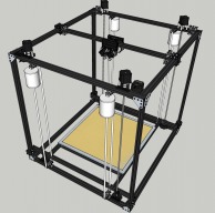
  1. Giuliano M

    Giuliano M Well-Known
    Builder

    Joined:
    Apr 3, 2014
    Messages:
    193
    Likes Received:
    39
  2. Giuliano M

    Giuliano M Well-Known
    Builder

    Joined:
    Apr 3, 2014
    Messages:
    193
    Likes Received:
    39
    The counterbalance mechanism:

    A 3" diameter PVC pipe with caps on both ends, filled with recycled lead shot - about 7-8 pounds worth.

    See the BOM for the lead shot - it comes in a 25 pound bag.


    One counterweight per Z-axis lead screw (4 total), to balance out the ~25 pounds of weight that the gantry assembly will weigh.

    Two sets of idler roller bearings at top and bottom, with something like 1/4" paracord tying up in a loop.

    The back side of the cord will be tied/bolted/clamped to the Z-axis gantry, and will pull upwards as the weight is pulled downwards by gravity.
     

    Attached Files:

  3. Giuliano M

    Giuliano M Well-Known
    Builder

    Joined:
    Apr 3, 2014
    Messages:
    193
    Likes Received:
    39
    X/Y gantry carriage, assembled with 4 x E3D Titan Aero Extruders and Volcano Hot Ends.

    A Duet Wifi (or the new Ethernet model) plus a Duex5 expansion board will be required to drive all 10 steppers - 4 on the Z axis, 2 on the CoreXY, and 4 on the Extruders.

    Though initially I will probably start with 2 extruder assemblies due to cost.


    I'll still need the Duet and Duex5 to get the assembly moving, though.

    There is plenty of room for all 4 Volcano nozzles to reach all four corners of the PEI print surface.

    Maximum height from the nozzles to the bed would be about 785mm.
     

    Attached Files:

  4. Giuliano M

    Giuliano M Well-Known
    Builder

    Joined:
    Apr 3, 2014
    Messages:
    193
    Likes Received:
    39
    Possible interference area between one of the extruder fans and the cord for the counterweights.

    This is with the furthest nozzle directly over one of the corners of the bed.

    Everything else has clearance, though.
     

    Attached Files:

  5. Giuliano M

    Giuliano M Well-Known
    Builder

    Joined:
    Apr 3, 2014
    Messages:
    193
    Likes Received:
    39
    The aluminum plate itself weighs about 17 pounds...

    The rails weigh .75 kg per 1000mm, and there's enough in the Z Assembly to weigh 5 pounds or so...

    So yes, I figure 20-25 pounds that need to be compensated.

    I calculated the volume of the counterweight canisters, and that's about 5-7 pounds each when filled with lead shot.
     
  6. Giuliano M

    Giuliano M Well-Known
    Builder

    Joined:
    Apr 3, 2014
    Messages:
    193
    Likes Received:
    39
    Updated the Sketchup file and BOM list.

    Added the Mini Differential IR sensor to BOM.


    I'm thinking of designing a cleaning station on the front and back sides of the top, something with a platform and some brass bristle brushes that the nozzle heads can move over to clean themselves.
     

    Attached Files:

  7. ChuckWheat

    Builder

    Joined:
    Mar 10, 2017
    Messages:
    3
    Likes Received:
    0
    wow! really looking forward to seeing how this thing turns out. It's a great build volume. Might build one for the lab at my university :).
     
  8. Giuliano M

    Giuliano M Well-Known
    Builder

    Joined:
    Apr 3, 2014
    Messages:
    193
    Likes Received:
    39
    Thanks!

    The build volume is actually constrained by a few factors:

    V-Slot Lengths of 1000mm max - though 1500mm is available.

    Leadscrew max lengths of 1000mm (1040mm actual) - limits the height.

    Print Surface - 24" x 24" is the largest sheet of PEI that I can get at a reasonable cost.

    Cuts - there should be a maximum of 5 cuts to be made, accurate to the nearest mm. The rest of the lengths are stock 1000mm, and the factory does a good job on those.
     
  9. Giuliano M

    Giuliano M Well-Known
    Builder

    Joined:
    Apr 3, 2014
    Messages:
    193
    Likes Received:
    39
    Replacing the long 44mm Nema 17 stepper motors on the Titan extruders with the recommended 22mm "Pancake" steppers gives me a lot more room on the carriage assembly.

    It actually lets me replace the 80mm V-Slot with 60mm V-Slot, and raises it up by 20mm.

    It also will greatly reduce the weight of the carriage.
     

    Attached Files:

  10. Giuliano M

    Giuliano M Well-Known
    Builder

    Joined:
    Apr 3, 2014
    Messages:
    193
    Likes Received:
    39
    Bill of Materials is finalized, barring minor additions.

    Hardware total is about $1500.

    Electronics total is about $1400.


    I'm going to order all of the Openbuilds hardware soon... anybody have a discount code? :)

    The electronics will follow later, I'm going to try to space out the purchases to one per month once I have the hardware built.
     
  11. Giuliano M

    Giuliano M Well-Known
    Builder

    Joined:
    Apr 3, 2014
    Messages:
    193
    Likes Received:
    39
    Well, I ordered all of the hardware parts.

    There goes my wallet... :)
     
  12. Giuliano M

    Giuliano M Well-Known
    Builder

    Joined:
    Apr 3, 2014
    Messages:
    193
    Likes Received:
    39
    I've even worked out a simple enclosure - 5mm plywood, bolted to the sides with 20mm standoffs in four corners.

    Back panel will probably just be attached to the side panels, maybe print some hinges with pins that can be removed.

    The front panels will probably be a pair of 24x48" plexiglass doors.
     

    Attached Files:

  13. Giuliano M

    Giuliano M Well-Known
    Builder

    Joined:
    Apr 3, 2014
    Messages:
    193
    Likes Received:
    39
    Designed a mounting plate for the Mini Differential IR sensor board for the Z-probe.

    Also figured out that there's room underneath the carriage for 4 x 5015 Blower Fans, to cool the print.

    Not quite sure how I'm going to mount the fans, I'm thinking maybe a plate sandwiched in between the pairs of fans, adhered with double-sided foam tape..
     

    Attached Files:

  14. Giuliano M

    Giuliano M Well-Known
    Builder

    Joined:
    Apr 3, 2014
    Messages:
    193
    Likes Received:
    39
  15. Giuliano M

    Giuliano M Well-Known
    Builder

    Joined:
    Apr 3, 2014
    Messages:
    193
    Likes Received:
    39
    I designed up some simple mounting plates for the 5015 Blower Fan mounts (print cooling fans).

    Just some plates with 4mm mounting holes for the fans, and 5mm holes for M5 screws to thread into the ends of the carriage V-slot plates.

    The plates will have some ~38mm holes cut in the middle for the air intake of the blowers, half of them will have to be mounted with the air intake towards the inside of the frame.


    Also placed the Differential IR sensor plate in the middle between the two extruders.

    Plenty of room, and it's best when the sensor is closer to the extruder points.
     

    Attached Files:

  16. Giuliano M

    Giuliano M Well-Known
    Builder

    Joined:
    Apr 3, 2014
    Messages:
    193
    Likes Received:
    39
    The 110V 600x600mm silicone heater arrived - 2000 watts.

    I already received an AC-DC Solid State Relay with a heatsink to drive it.


    Also - I have heard about integrating a thermal cutout or thermal cutoff to prevent the heater from getting stuck in an "On" state.

    However, I'm not sure what kind to get - I presume it should cut out at around 120-130C, and be rated for 110-120V AC.

    Anybody have any suggestions?
     

    Attached Files:

  17. Giuliano M

    Giuliano M Well-Known
    Builder

    Joined:
    Apr 3, 2014
    Messages:
    193
    Likes Received:
    39
    That's a lot of OpenBuilds hardware! :)
     

    Attached Files:

  18. Giuliano M

    Giuliano M Well-Known
    Builder

    Joined:
    Apr 3, 2014
    Messages:
    193
    Likes Received:
    39
    Went by the hardware store today and picked up a length of 1/8" x 1" aluminum flat bar, to make the IR sensor mounting bar.

    I also picked up some 4"x10" plates of aluminum:

    .064" (1.6mm) thick to make the blower fan mounting plates - it's thick enough that it's not going to bend under hand pressure.

    The fan mounting plates are 58mm square, and the stock is 254mm (10") long.


    I also picked up two sheets of .016" (0.4mm), which I plan to use to cut and bend into nozzles/ducts to attach to the ends of the blower fans.

    My plan is to design the nozzle shape in Fusion 360 (it has a sheet metal module), and then cut and fold together into shape, and braze (solder) the edges with aluminum brazing rod and a propane torch.
     

    Attached Files:

  19. Giuliano M

    Giuliano M Well-Known
    Builder

    Joined:
    Apr 3, 2014
    Messages:
    193
    Likes Received:
    39
    Simple nozzle design, 0.4mm wall thickness.

    Blower end is about 15x20mm, output end is about 5x10mm.

    Nozzle blows down, not left/right - the output is just above the nozzle bottom.
     

    Attached Files:

  20. Giuliano M

    Giuliano M Well-Known
    Builder

    Joined:
    Apr 3, 2014
    Messages:
    193
    Likes Received:
    39
    Redesigned the fan duct to be a two-piece design.

    Unwrapped the outer surfaces and laid them flat, and now I have a cutting template.


    Print out to scale, adhere to the aluminum stock, cut the edges and score the lines, and fold.

    Once folded and the edges meet, braze/solder the edges with a propane torch and aluminum brazing rods.
     

    Attached Files:

  21. Giuliano M

    Giuliano M Well-Known
    Builder

    Joined:
    Apr 3, 2014
    Messages:
    193
    Likes Received:
    39
    Papercraft proof of concept for the blower nozzle.

    Folded up and glued the seams, and it seems to fit well.
     

    Attached Files:

  22. Giuliano M

    Giuliano M Well-Known
    Builder

    Joined:
    Apr 3, 2014
    Messages:
    193
    Likes Received:
    39
    Modeling the plastic cable chain that I got from eBay.

    I got 3 x 1 Meter lengths of 10x20mm cable chain, and I'm trying to figure out how to mount it.

    One section will go along the Y axis - either above or below, not sure which.

    The second section will go across the X axis with the carriage.

    The third was for the Z axis, but I can probably get away with cable spiral wrap if I need to cannibalize the third meter for additional sections.
     

    Attached Files:

  23. Giuliano M

    Giuliano M Well-Known
    Builder

    Joined:
    Apr 3, 2014
    Messages:
    193
    Likes Received:
    39
    The cable chain needs to be supported from underneath, to reduce the drag on the moving ends.

    Some 1.5" x 0.75" x 0.125" (WxHxWall) aluminum C channel is just about the right size.

    The plastic cable chain is just a hair over 1" wide and 0.5" tall. The minimum diameter of the bend portion is about 2.5".


    A channel supported over the X gantry will carry the cables on the X axis, and the channel suspended under the Y axis end will carry the cables through the Y axis.
     

    Attached Files:

  24. Giuliano M

    Giuliano M Well-Known
    Builder

    Joined:
    Apr 3, 2014
    Messages:
    193
    Likes Received:
    39
    So these little rubber feet that I got via eBay are actually pretty nice.

    The rubber portion is 15mm diameter x 15mm long, and the thread is 10mm M5 thread.

    Screwed into the V-Slot with a T-nut, and they stick out almost exactly 20mm.


    They could also probably be used as axis bumpers, to prevent the carriages from smashing into the ends.

    I got a 10-pack, I may have to get another 10-pack.
     

    Attached Files:

  25. Shortyski13

    Builder

    Joined:
    Mar 28, 2017
    Messages:
    40
    Likes Received:
    9
    Go 1500mm height! That's what I'm planning to do! Get longer lead screws from here: Buy Precision Components - AccuGroup. They are even at very good prices if you aren't going for stainless. I was almost going to switch my design from lead screw to a belt-driven z-axis, but then I saw your idea of counter-weighting the bed and thought that was a good idea. I'm curious how your z-wobble comes out, if there is any at all, with this setup. Also, I would think you may want to constrain your weights a bit just to make sure they don't swing at all (though with the small step each time, they shouldn't).
     
  26. Giuliano M

    Giuliano M Well-Known
    Builder

    Joined:
    Apr 3, 2014
    Messages:
    193
    Likes Received:
    39
    Thanks for the recommendation - I already bought the rails and rods, but the design should be easy to update with 1500mm lengths... I just have to replace the uprights and the ACME rods.


    There really shouldn't be any Z-wobble, as the 4 steppers on the Z axis should step in-sync once the four corners are homed.

    That is why I am going with a full Duet Wifi and Expansion board - the Z axis alone will require 4 separate steppers, plus two for X/Y, and 4 for extruders - maxing out at 10 drivers.

    Plus, the Duet firmware has some provisions for homing the four Z steppers together, and then independently homing each corner via the Z-axis IR probe.


    The counterbalance weights will be tied together in a loop, not free-hanging. They shouldn't swing at all, or very little.
     
  27. Giuliano M

    Giuliano M Well-Known
    Builder

    Joined:
    Apr 3, 2014
    Messages:
    193
    Likes Received:
    39
    The prices do seem pretty good - though the minimum screw diameter is 10mm, so I'd have to create new methods of holding the rods, as the OpenBuilds leadscrew parts are all 8mm diameter.

    Not that a 10-12mm diameter lead screw would be bad for the taller 1500mm height, most seem to be 1-start threads with 2-4mm per revolution, so there's that.


    I will stick with the planned 1000mm heights for now.
     
  28. Shortyski13

    Builder

    Joined:
    Mar 28, 2017
    Messages:
    40
    Likes Received:
    9
    Also I feel like, especially with a counterweighted bed, you should be able to use 12mm lead screws. I ran an Ansys analys on qty 3x 12mm screws placed in a triangle around the bed frame, fixed the bottoms, and put 16 lb vertical load at the top (1400mm), and it outputted .0014 inches deflection in X direction, .00008 inch vertical deflection. Those numbers are pretty small, more so if counterweighted: Divide those numbers by 16 if you plan on having just 1lb of load and divide by 4 if planning to make a pretty big print; divide by 3 if planning to make a huge 2kg print +1lb print bed (roughly) which still is very small numbers.
    Honestly the biggest reason I'm looking at 12mm screws for my project now is because I can't find inexpensive pillow blocks or equivalent to mount anything larger :-/ I'm on a much tighter budget than you it seems, which is awesome for you. (I'm trying to somewhat save for a wedding).
    I don't think i've seen a printer with both screws and counterweights; I love this idea and really look forward to hearing how it works out! Personally, I like the idea of the leads screws all driven synchronously by a timing belt instead of separate motors, but if you can get that to work then great! I'm also aiming to use a duet, mostly because I want the option to be able to run 2.8a nema23's if I decide I want to upgrade to them (and i'm planning on a 23 for the z-axis anyway). Duetwifi's latest firmware will allow 2.4a current to the drivers which I think should be enough. Good luck :)
     
  29. Giuliano M

    Giuliano M Well-Known
    Builder

    Joined:
    Apr 3, 2014
    Messages:
    193
    Likes Received:
    39
    I, too, will be running 2.8a Nema23's - 0.9 degree ones.

    The 2.4A should be enough.
     
    Shortyski13 likes this.
  30. robb_nl

    robb_nl New
    Builder

    Joined:
    Apr 22, 2017
    Messages:
    3
    Likes Received:
    2
    Great project! Following!
    I am a complete novice on designing a 3D printer, but doing a lot of reading to e able to start my own project soon: a coreX-Y printer with a 300 x 300 x 500mm printvolume.
    My first reaction to your build is: It seems greatly over dimensioned. Did you do any calculations? Is it your experience that you need these heavy extrusion lengths?
    A 1/4inch aluminum slab + a PEI sheet: do you need 1/4inch thick or could this be thinner?
    Ever thought of using a sliding parallel table instead of counterweights? It will reduce weight dramatically.
     

Share This Page

  1. This site uses cookies to help personalise content, tailor your experience and to keep you logged in if you register.
    By continuing to use this site, you are consenting to our use of cookies.
    Dismiss Notice